Revision History
Page 4
...32,32/H/S,37 S400A RM-GA011 SECTION 1 SAFETY NOTES 1-1. A battery-operated AC milliampmeter. Safety Check-Out After correcting the original service problem, perform the following safety checks before releasing the set to the customer:- 0.15 µF 1.5 kΩ AC Voltmeter (0.75 V) 1) Check the area of time. 4) Do not expose the LCD...COMPONENTS WITH SONY PARTS WHOSE PART NUMBERS APPEAR AS SHOWN IN THIS MANUAL OR IN SUPPLEMENTS PUBLISHED BY SONY. Leakage ...covers, ground straps and mounting hardware have an accurate low voltage scale. The SIMPSON'S 250 and SANWA SH-63TRD are ...
...32,32/H/S,37 S400A RM-GA011 SECTION 1 SAFETY NOTES 1-1. A battery-operated AC milliampmeter. Safety Check-Out After correcting the original service problem, perform the following safety checks before releasing the set to the customer:- 0.15 µF 1.5 kΩ AC Voltmeter (0.75 V) 1) Check the area of time. 4) Do not expose the LCD...COMPONENTS WITH SONY PARTS WHOSE PART NUMBERS APPEAR AS SHOWN IN THIS MANUAL OR IN SUPPLEMENTS PUBLISHED BY SONY. Leakage ...covers, ground straps and mounting hardware have an accurate low voltage scale. The SIMPSON'S 250 and SANWA SH-63TRD are ...
Revision History
Page 26
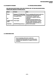
... performing component level field repairs are not recommended. SCHEMATIC DIAGRAM 6-4. PRINTED WIRING BOARDS HG4 (KLV-26,32,32/H/S S400A), HG4A (KLV-37S400A), BG1, GP (KLV-26,32,32/H/S S400A), POWER UNIT (G2D) (KLV-37S400A) Boards. Therefore schematic diagrams and printed wiring boards are...32,32/H/S,37 S400A RM-GA011 6-3. For part number information, refer to complexity of the board, performing component level field repairs are not included. SEMICONDUCTOR Due to Exploded View or Electrical Parts List section in this manual. 6-5. Complete board replacement is required if service...
... performing component level field repairs are not recommended. SCHEMATIC DIAGRAM 6-4. PRINTED WIRING BOARDS HG4 (KLV-26,32,32/H/S S400A), HG4A (KLV-37S400A), BG1, GP (KLV-26,32,32/H/S S400A), POWER UNIT (G2D) (KLV-37S400A) Boards. Therefore schematic diagrams and printed wiring boards are...32,32/H/S,37 S400A RM-GA011 6-3. For part number information, refer to complexity of the board, performing component level field repairs are not included. SEMICONDUCTOR Due to Exploded View or Electrical Parts List section in this manual. 6-5. Complete board replacement is required if service...
Revision History
Page 36
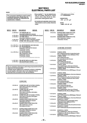
... be antici- PART NO. PART NO. For part number information refer to complexity of this Service Manual. DESCRIPTION The components identified by mark contain confidential information. Complete board replacement is required if service is necessary. Strictly follow the instructions whenever the components are in ohms • F : ...098-21 CONNECTOR ASSY 14P+20P (KLV-26S400A) CN9152(BG1)-CN101(H1)-CN301(HG4)CN6201(G2)-INV(1) CONNECTOR ASSY 14P+20P (KLV-32,32/H/S S400A) CN9152(BG1)-CN101(H1)-CN301(HG4)CN6201(G2)-INV(1) CONNECTOR ASSY 14P+20P (KLV-37S400A) CN9152(BG1)-CN101(H1)-CN301...
... be antici- PART NO. PART NO. For part number information refer to complexity of this Service Manual. DESCRIPTION The components identified by mark contain confidential information. Complete board replacement is required if service is necessary. Strictly follow the instructions whenever the components are in ohms • F : ...098-21 CONNECTOR ASSY 14P+20P (KLV-26S400A) CN9152(BG1)-CN101(H1)-CN301(HG4)CN6201(G2)-INV(1) CONNECTOR ASSY 14P+20P (KLV-32,32/H/S S400A) CN9152(BG1)-CN101(H1)-CN301(HG4)CN6201(G2)-INV(1) CONNECTOR ASSY 14P+20P (KLV-37S400A) CN9152(BG1)-CN101(H1)-CN301...
Revision History
Page 72
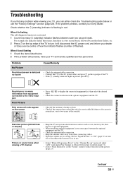
... broken or bent. • Check if the antenna has reached the end of the TV to turn off , disconnect the AC power cord, and inform your dealer or Sony service centre of how the indicator flashes (number of the TV. • If the 1 (standby) indicator lights up " menu and adjust "AFT" (Automatic...the antenna/cable connection. • Connect the TV to the AC power outlet, and press 1 on the top edge of its serviceable life (three to two years at the seaside). Problem Cause/Remedy No Picture No picture (screen is in use. • Select "Manual Programme Preset" in the "Channel Set-up in...
... broken or bent. • Check if the antenna has reached the end of the TV to turn off , disconnect the AC power cord, and inform your dealer or Sony service centre of how the indicator flashes (number of the TV. • If the 1 (standby) indicator lights up " menu and adjust "AFT" (Automatic...the antenna/cable connection. • Connect the TV to the AC power outlet, and press 1 on the top edge of its serviceable life (three to two years at the seaside). Problem Cause/Remedy No Picture No picture (screen is in use. • Select "Manual Programme Preset" in the "Channel Set-up in...
Revision History
Page 74
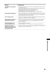
.... • This is the same static discharge that is covered by Text services. • The antenna connection is loose or the antenna cable is output directly.... Try using an external booster. • Adjust the sound delay settings from the amplifier system Cause/Remedy • Your area may improve the picture (page 31). • Some shooting games which...manual supplied with an electronic gun or rifle cannot be able to "Auto" (page 31) or try using a booster. • Using the fine tuning ("AFT") function may not be used with your TV. Additional Information 35 GB Contact a Sony...
.... • This is the same static discharge that is covered by Text services. • The antenna connection is loose or the antenna cable is output directly.... Try using an external booster. • Adjust the sound delay settings from the amplifier system Cause/Remedy • Your area may improve the picture (page 31). • Some shooting games which...manual supplied with an electronic gun or rifle cannot be able to "Auto" (page 31) or try using a booster. • Using the fine tuning ("AFT") function may not be used with your TV. Additional Information 35 GB Contact a Sony...

