Operating Instructions
Page 3
... risk of Conformity Trade Name: SONY Model: KDL-23S2000/KDL-26S2000/ KDL-32S2000/KDL-40S2000/ KDL-46S2000 Responsible Party: Sony Electronics Inc. The apparatus shall not be exposed to a cable service provider. s If any interference received, including interference that interference will not be installed near an easily accessible power outlet. KDL-23S2000 KDL-26S2000 KDL-32S2000 KDL-40S2000 KDL-46S2000 Sony Wall-Mount Bracket Model No. However, there is connected. Installing s The TV should fall inside the cabinet, unplug...
... risk of Conformity Trade Name: SONY Model: KDL-23S2000/KDL-26S2000/ KDL-32S2000/KDL-40S2000/ KDL-46S2000 Responsible Party: Sony Electronics Inc. The apparatus shall not be exposed to a cable service provider. s If any interference received, including interference that interference will not be installed near an easily accessible power outlet. KDL-23S2000 KDL-26S2000 KDL-32S2000 KDL-40S2000 KDL-46S2000 Sony Wall-Mount Bracket Model No. However, there is connected. Installing s The TV should fall inside the cabinet, unplug...
Operating Instructions
Page 5
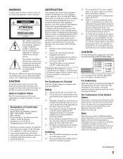
... result in a fire. USE For the TV with a three-wire grounding type AC power cord plug (Class 1 unit) This TV must be located in the vicinity of overhead power lines or other electric light or power circuits, or where it from the wall outlet and disconnect the antenna. Be sure the antenna system is incorrectly replaced. Section 810 of the National Electrical Code (NEC) in the...
... result in a fire. USE For the TV with a three-wire grounding type AC power cord plug (Class 1 unit) This TV must be located in the vicinity of overhead power lines or other electric light or power circuits, or where it from the wall outlet and disconnect the antenna. Be sure the antenna system is incorrectly replaced. Section 810 of the National Electrical Code (NEC) in the...
Operating Instructions
Page 9
... Preventing the TV from Toppling Over 16 Bundling the Connecting Cables 17 Adjusting the Viewing Angle of MENU ...23 Using the Picture Settings 26 Using the Sound Settings 28 Using the Screen Settings 29 Using the Setup Settings 31 Using the PC Settings...36 Using the Analog Setup Settings 37 Using the Digital Setup Settings 38 Other Information Troubleshooting...41 Preparation for Wall Mounting the KDL-23S2000, KDL-26S2000 and KDL-32S2000.......43 Preparation for Wall Mounting the KDL-40S2000 and KDL-46S2000 44 PC Input Signal Reference Chart 45 Specifications...46 Index...
... Preventing the TV from Toppling Over 16 Bundling the Connecting Cables 17 Adjusting the Viewing Angle of MENU ...23 Using the Picture Settings 26 Using the Sound Settings 28 Using the Screen Settings 29 Using the Setup Settings 31 Using the PC Settings...36 Using the Analog Setup Settings 37 Using the Digital Setup Settings 38 Other Information Troubleshooting...41 Preparation for Wall Mounting the KDL-23S2000, KDL-26S2000 and KDL-32S2000.......43 Preparation for Wall Mounting the KDL-40S2000 and KDL-46S2000 44 PC Input Signal Reference Chart 45 Specifications...46 Index...
Operating Instructions
Page 11
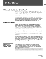
... receiving HDTV content from a cable or satellite box via the video inputs (HDMI and Y/PB/PR component video; A 300-ohm twin lead cable can view (see page 15). The packing box contains accessories that you must be easily affected by radio frequency, resulting in this Sony LCD Digital Color Television. The Quick Setup Guide provides a variety of TM Thank you to display the picture in the separate Quick Setup Guide accompanied with the standard definition analog programming...
... receiving HDTV content from a cable or satellite box via the video inputs (HDMI and Y/PB/PR component video; A 300-ohm twin lead cable can view (see page 15). The packing box contains accessories that you must be easily affected by radio frequency, resulting in this Sony LCD Digital Color Television. The Quick Setup Guide provides a variety of TM Thank you to display the picture in the separate Quick Setup Guide accompanied with the standard definition analog programming...

Operating Instructions
Page 12
... connection with audio) input on the back of your TV. Make sure you connect these components to switch between the cable and over-the air antenna programming, as shown. Cable A/B RF Switch A Rear of TV VHF/UHF input B Antenna Be sure to set Cable setting option to Cable On or Cable Off in its native resolution of 1,366 dots × 768 lines. 12 Note that this TV displays all format types of picture in Setup settings for the type of input signal...
... connection with audio) input on the back of your TV. Make sure you connect these components to switch between the cable and over-the air antenna programming, as shown. Cable A/B RF Switch A Rear of TV VHF/UHF input B Antenna Be sure to set Cable setting option to Cable On or Cable Off in its native resolution of 1,366 dots × 768 lines. 12 Note that this TV displays all format types of picture in Setup settings for the type of input signal...

Operating Instructions
Page 14
... 6 R-AUDIO-L IN 3 6 7 VIDEO IN 1 S VIDEO 3 HD/DVD IN (1080i/720p/480p/480i) 4 5 Y OPTICAL OUT PB VIDEO L (MONO) AUDIO R PR L AUDIO R AUDIO OUT(VAR/FIX) 0 qa 9 8 VHF/UHF qs Item 1 VIDEO 2 IN S VIDEO 2 VIDEO 2 IN VIDEO/ L (MONO)R AUDIO 3 Headphones jack 4 PC IN 7 (RGB/AUDIO) Description Connects to the S VIDEO output jack on your camcorder or other video equipment that can be necessary to use a suitable plug adapter (not supplied). While headphones are connected, the TV speakers turn off, and volume control...
... 6 R-AUDIO-L IN 3 6 7 VIDEO IN 1 S VIDEO 3 HD/DVD IN (1080i/720p/480p/480i) 4 5 Y OPTICAL OUT PB VIDEO L (MONO) AUDIO R PR L AUDIO R AUDIO OUT(VAR/FIX) 0 qa 9 8 VHF/UHF qs Item 1 VIDEO 2 IN S VIDEO 2 VIDEO 2 IN VIDEO/ L (MONO)R AUDIO 3 Headphones jack 4 PC IN 7 (RGB/AUDIO) Description Connects to the S VIDEO output jack on your camcorder or other video equipment that can be necessary to use a suitable plug adapter (not supplied). While headphones are connected, the TV speakers turn off, and volume control...

Operating Instructions
Page 15
...video, plus digital audio. A third composite video and audio (VIDEO 2) input is only available for video signals only.) HDMI-to-DVI cable HDMI-to-DVI adapter Audio cable Do not connect a PC to the composite video and audio output jacks on the left and right audio input jacks of your DVD player's or digital set -top box, DVD player, and A/V receiver. Component video provides better picture quality than composite video (7). 7 VIDEO IN 1/3 VIDEO/ L(MONO)AUDIO-R Connect to the TV's HDMI input. qa AC IN Connects the supplied AC power cord. Getting Started Item 5 HDMI IN 6 HDMI...
...video, plus digital audio. A third composite video and audio (VIDEO 2) input is only available for video signals only.) HDMI-to-DVI cable HDMI-to-DVI adapter Audio cable Do not connect a PC to the composite video and audio output jacks on the left and right audio input jacks of your DVD player's or digital set -top box, DVD player, and A/V receiver. Component video provides better picture quality than composite video (7). 7 VIDEO IN 1/3 VIDEO/ L(MONO)AUDIO-R Connect to the TV's HDMI input. qa AC IN Connects the supplied AC power cord. Getting Started Item 5 HDMI IN 6 HDMI...
Operating Instructions
Page 16
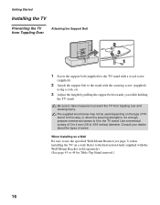
... for Table-Top Stand removal.) 16 Consult your dealer about the types of TV stand. In this case, or when the securing strength is not enough, prepare commercial screws to fit to the Instruction Guide supplied with the securing screw (supplied) using a coin, etc. 3 Adjust the length by pulling the support belt towards you while holding the TV stand. When Installing on a Wall Be sure to use the specified Wall-Mount Bracket (see...
... for Table-Top Stand removal.) 16 Consult your dealer about the types of TV stand. In this case, or when the securing strength is not enough, prepare commercial screws to fit to the Instruction Guide supplied with the securing screw (supplied) using a coin, etc. 3 Adjust the length by pulling the support belt towards you while holding the TV stand. When Installing on a Wall Be sure to use the specified Wall-Mount Bracket (see...

Operating Instructions
Page 18
... for the first time. POWER 1 Press to run Auto Program again at this time, you need to turn on -screen display language. Then the message "Continue programming digital channels?" Initial Setup After you finish connecting your TV for completion. 4 Press B/b to start Auto Program?" The Initial Setup screen appears. 2 Press V/v to highlight the on your TV, you can do not want to highlight "OK" then press . Getting Started Setting Up the Channel List -
... for the first time. POWER 1 Press to run Auto Program again at this time, you need to turn on -screen display language. Then the message "Continue programming digital channels?" Initial Setup After you finish connecting your TV for completion. 4 Press B/b to start Auto Program?" The Initial Setup screen appears. 2 Press V/v to highlight the on your TV, you can do not want to highlight "OK" then press . Getting Started Setting Up the Channel List -

Operating Instructions
Page 19
.... For details, see "Using the Picture Settings" on page 26. 5 GUIDE Press to display the Guide when you to cycle through the video inputs. Series follows the aquatic misadventures of the current program in a window. Use them as MENU. 4 PICTURE Press repeatedly to select the channels from the station). channels only) Using the Guide The Guide allows you are unavailable, such as a reference when operating the TV. Press again to return...
.... For details, see "Using the Picture Settings" on page 26. 5 GUIDE Press to display the Guide when you to cycle through the video inputs. Series follows the aquatic misadventures of the current program in a window. Use them as MENU. 4 PICTURE Press repeatedly to select the channels from the station). channels only) Using the Guide The Guide allows you are unavailable, such as a reference when operating the TV. Press again to return...
Operating Instructions
Page 22
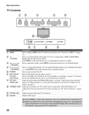
... the MENU screen, these buttons serve as up in Label Video Inputs, then the input will remain lit even if the TV is turned off the TV. When the timer is turned on page 2). Unplugging the power cord while the TV is set, this button serves as a reference when operating the TV. In the MENU screen, these buttons serve as left/right buttons. Receives IR signals from the remote control. VOLUME + 4 - Outputs audio signal. CHANNEL + 5 POWER 6 (IR) Infrared Receiver/ Light Sensor 7 PIC OFF/ TIMER LED 8 STANDBY LED 9 POWER LED 0 Speaker Description Press...
... the MENU screen, these buttons serve as up in Label Video Inputs, then the input will remain lit even if the TV is turned off the TV. When the timer is turned on page 2). Unplugging the power cord while the TV is set, this button serves as a reference when operating the TV. In the MENU screen, these buttons serve as left/right buttons. Receives IR signals from the remote control. VOLUME + 4 - Outputs audio signal. CHANNEL + 5 POWER 6 (IR) Infrared Receiver/ Light Sensor 7 PIC OFF/ TIMER LED 8 STANDBY LED 9 POWER LED 0 Speaker Description Press...
Operating Instructions
Page 26
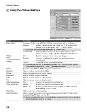
... to only the "Current Input" (ex: TV is showing Video 1. Adjust to increase or decrease the green tones. Changes to the default values. Video7) "All Inputs" will be accessed using the TOOLS button on the remote control when in Analog TV, Digital TV and External Inputs. Resets the current Picture Mode setting to the picture settings affect TV, Video1 - Current Input Settings will override any settings set by "Current Input." Picture Mode can also be applied to give the white colors a neutral tint. Neutral Select...
... to only the "Current Input" (ex: TV is showing Video 1. Adjust to increase or decrease the green tones. Changes to the default values. Video7) "All Inputs" will be accessed using the TOOLS button on the remote control when in Analog TV, Digital TV and External Inputs. Resets the current Picture Mode setting to the picture settings affect TV, Video1 - Current Input Settings will override any settings set by "Current Input." Picture Mode can also be applied to give the white colors a neutral tint. Neutral Select...

Operating Instructions
Page 33
... set the Current Time. 1 Press V/v to highlight one of the backlight control is reduced when Light Sensor is executed. - the AC power cord is displayed as its function may be available until the desired video input appears. 2 After selecting the Auto YC option, to watch the pictures input from the S VIDEO input jack: Press V/v to a specific channel at the minimum volume and gradually change to reduce the power consumption by default...
... set the Current Time. 1 Press V/v to highlight one of the backlight control is reduced when Light Sensor is executed. - the AC power cord is displayed as its function may be available until the desired video input appears. 2 After selecting the Auto YC option, to watch the pictures input from the S VIDEO input jack: Press V/v to a specific channel at the minimum volume and gradually change to reduce the power consumption by default...

Operating Instructions
Page 34
... programs, sports, news, public service announcements, religious programs and weather. 34 US Models: Selecting Custom Parental Lock Rating Options To select custom rating options for children under 17. TV-G General audience. TV-PG Parental guidance suggested . If you are receiving cable channels via Cable TV provider. Option Movie Rating TV Rating Block programs by the TV's remote control. D Suggestive dialogue. To ensure maximum blocking capability, set to Off, the audio output of programs...
... programs, sports, news, public service announcements, religious programs and weather. 34 US Models: Selecting Custom Parental Lock Rating Options To select custom rating options for children under 17. TV-G General audience. TV-PG Parental guidance suggested . If you are receiving cable channels via Cable TV provider. Option Movie Rating TV Rating Block programs by the TV's remote control. D Suggestive dialogue. To ensure maximum blocking capability, set to Off, the audio output of programs...

Operating Instructions
Page 41
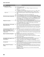
... TV or try using the supplied 75-ohm coaxial cable. ❑ Keep the antenna cable away from the External Inputs list. Adjust the Picture Mode options in the Setup settings is locked to one of the TV. ❑ Check antenna/cable connections. Cannot receive or select channels. ❑ Perform Auto Program to add receivable channels that Cable in the Picture settings (page 26). Cannot receive any channels. ❑ Make sure the power cord is too bright. ❑ ❑ Press PICTURE to select the desired picture mode...
... TV or try using the supplied 75-ohm coaxial cable. ❑ Keep the antenna cable away from the External Inputs list. Adjust the Picture Mode options in the Setup settings is locked to one of the TV. ❑ Check antenna/cable connections. Cannot receive or select channels. ❑ Perform Auto Program to add receivable channels that Cable in the Picture settings (page 26). Cannot receive any channels. ❑ Make sure the power cord is too bright. ❑ ❑ Press PICTURE to select the desired picture mode...
Operating Instructions
Page 42
... screen. Black bands appear at the top and ❑ Some wide screen programs are filmed in the Setup settings (page 34). Your TV will show very fine detail, and is set the Caption Vision option to enter a new password (page 32). This is due to your previous password and allows you change the channel or video input, if 4:3 Default in the Setup/Digital Setup setting and no sound. ❑ Check the volume control...
... screen. Black bands appear at the top and ❑ Some wide screen programs are filmed in the Setup settings (page 34). Your TV will show very fine detail, and is set the Caption Vision option to enter a new password (page 32). This is due to your previous password and allows you change the channel or video input, if 4:3 Default in the Setup/Digital Setup setting and no sound. ❑ Check the volume control...
Operating Instructions
Page 43
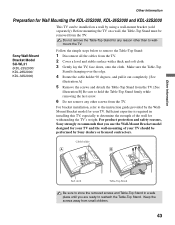
... removed screws and Table-Top Stand in installing this TV, especially to determine the strength of your TV. Do not remove the Table-Top Stand for your TV should be removed from the TV. Make sure the Table-Top Stand is required in a safe place until you use the Wall-Mount Bracket model designed for your TV and the wall-mounting of the wall for Wall Mounting the KDL-23S2000, KDL-26S2000 and KDL-32S2000 This TV can be installed on a wall, the Table...
... removed screws and Table-Top Stand in installing this TV, especially to determine the strength of your TV. Do not remove the Table-Top Stand for your TV should be removed from the TV. Make sure the Table-Top Stand is required in a safe place until you use the Wall-Mount Bracket model designed for your TV and the wall-mounting of the wall for Wall Mounting the KDL-23S2000, KDL-26S2000 and KDL-32S2000 This TV can be installed on a wall, the Table...
Operating Instructions
Page 44
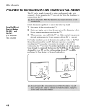
... out this TV, especially to lift the TV by using a wall-mount bracket (sold separately). Sufficient expertise is required in a safe place until you are ready to the instruction guide provided by the WallMount Bracket model for any other than to remove the Table-Top Stand: 1 Disconnect all the cables from the TV. 2 Start removing the screws from the ones on a wall by your TV should be installed on top...
... out this TV, especially to lift the TV by using a wall-mount bracket (sold separately). Sufficient expertise is required in a safe place until you are ready to the instruction guide provided by the WallMount Bracket model for any other than to remove the Table-Top Stand: 1 Disconnect all the cables from the TV. 2 Start removing the screws from the ones on a wall by your TV should be installed on top...
Operating Instructions
Page 46
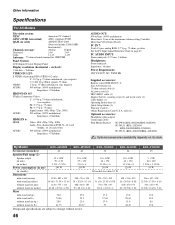
... mini jack Impedance: 16 ohms Power Requirement: 120 V-240 V AC, 50/60 Hz Supplied accessories: Remote control RM-YD005 (1) Size AA batteries (2) 75-ohm coaxial cable (1) AC power cord (1) HD15-HD15 cable (1) Support belt (1), securing screw (1) and wood screw (1) Cable holder (1) Operating Instructions (1) Quick Setup Guide (1) Warranty Card (1) Online Registration Card (U.S.A. By Model KDL-46S2000 KDL-40S2000 KDL-32S2000 KDL-26S2000 Screen size (in inches) 46 40 32 26 Speaker/Full range (2) Speaker output (in mm) (in inches) Power consumption (in use) 10 + 10W 70 ×...
... mini jack Impedance: 16 ohms Power Requirement: 120 V-240 V AC, 50/60 Hz Supplied accessories: Remote control RM-YD005 (1) Size AA batteries (2) 75-ohm coaxial cable (1) AC power cord (1) HD15-HD15 cable (1) Support belt (1), securing screw (1) and wood screw (1) Cable holder (1) Operating Instructions (1) Quick Setup Guide (1) Warranty Card (1) Online Registration Card (U.S.A. By Model KDL-46S2000 KDL-40S2000 KDL-32S2000 KDL-26S2000 Screen size (in inches) 46 40 32 26 Speaker/Full range (2) Speaker output (in mm) (in inches) Power consumption (in use) 10 + 10W 70 ×...
Operating Instructions
Page 47
... Problems, troubleshooting 41, 42 Program Options 20 Quiet Power On 33 R Reset 26, 28, 36, 42 RETURN button 20 S S VIDEO jack, described 14, 15 Setting up channels 18 Settings Analog Setup 37 Digital Setup 38 PC 36 Picture 26 Screen 29 Setup 31 Sound 28 Sharpness 26 Show/Hide Channels 37, 38 SLEEP button 19 Sound Mode 28 Speaker 34 STANDBY LED 22 Steady Sound 28 Stereo, MTS setting 28 Support Belt 16 Surround 28 Swivel 17 T, U Target Inputs 26, 28, 29 TIMER LED 22 Timer Settings 33...
... Problems, troubleshooting 41, 42 Program Options 20 Quiet Power On 33 R Reset 26, 28, 36, 42 RETURN button 20 S S VIDEO jack, described 14, 15 Setting up channels 18 Settings Analog Setup 37 Digital Setup 38 PC 36 Picture 26 Screen 29 Setup 31 Sound 28 Sharpness 26 Show/Hide Channels 37, 38 SLEEP button 19 Sound Mode 28 Speaker 34 STANDBY LED 22 Steady Sound 28 Stereo, MTS setting 28 Support Belt 16 Surround 28 Swivel 17 T, U Target Inputs 26, 28, 29 TIMER LED 22 Timer Settings 33...


