Operating Instructions
Page 2
... servicing to provide reasonable protection against harmful interference in this manual could void your Sony dealer regarding this product, you carry the display unit, hold the unit itself, not the speakers. These limits are located on the rear....operate this equipment does cause harmful interference to radio or television reception, which the receiver is no guarantee that to Part 15 of the FCC Rules. To avoid electrical shock, do so, the speakers may come out of Conformity Trade Name: SONY Model: FWD-40LX1/32LX1R Responsible Party: Sony Electronics Inc. Telephone Number...
... servicing to provide reasonable protection against harmful interference in this manual could void your Sony dealer regarding this product, you carry the display unit, hold the unit itself, not the speakers. These limits are located on the rear....operate this equipment does cause harmful interference to radio or television reception, which the receiver is no guarantee that to Part 15 of the FCC Rules. To avoid electrical shock, do so, the speakers may come out of Conformity Trade Name: SONY Model: FWD-40LX1/32LX1R Responsible Party: Sony Electronics Inc. Telephone Number...
Operating Instructions
Page 3
...) Indicator Section 8 (GB) Control Button Section (Top 8 (GB) Connector Panel 9 (GB) Remote Commander RM-980 11 (GB) Caution 13 (GB) Connections 14 (GB) Connecting the Speakers 14 (GB) Connecting the AC Power Cord 14 (GB) Cable management 15 (GB) Using On-screen Menus 16 (GB) Operating Through Menus 16 (GB) Menu Guide 16 (GB) GB Watching the Picture 21 (GB) Switching the Input Signal 21 (GB) Input Signal, Picture Mode and Display Status Information 22...
...) Indicator Section 8 (GB) Control Button Section (Top 8 (GB) Connector Panel 9 (GB) Remote Commander RM-980 11 (GB) Caution 13 (GB) Connections 14 (GB) Connecting the Speakers 14 (GB) Connecting the AC Power Cord 14 (GB) Cable management 15 (GB) Using On-screen Menus 16 (GB) Operating Through Menus 16 (GB) Menu Guide 16 (GB) GB Watching the Picture 21 (GB) Switching the Input Signal 21 (GB) Input Signal, Picture Mode and Display Status Information 22...
Operating Instructions
Page 5
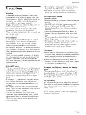
... Remote Commander, noisy picture, noisy sound, may occur. On the LCD panel • You may remove the coating or spoil the unit. When cleaning the panel face, wipe off grimy stains using a dry, soft cloth. • Never use the optional stand. When shipping the unit, repack it . Precautions On safety • A nameplate indicating operating voltage, power consumption, etc. On cleaning the display The panel...
... Remote Commander, noisy picture, noisy sound, may occur. On the LCD panel • You may remove the coating or spoil the unit. When cleaning the panel face, wipe off grimy stains using a dry, soft cloth. • Never use the optional stand. When shipping the unit, repack it . Precautions On safety • A nameplate indicating operating voltage, power consumption, etc. On cleaning the display The panel...
Operating Instructions
Page 7
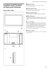
... connect the AC power cord, the POWER/STANDBY indicator lights up in red and the display goes into the standby mode. For more details on the power cord, see "Connecting the AC Power Cord" on page 14 (GB). 6 Connector panel For details on the connector panel, see "Control Button Section (Top)" on page 8 (GB). 3 Stand installation hooks Use these hooks to install the stand (not supplied). 4 SPEAKER Socket Connects the speakers (not supplied) to this socket and to output the audio matching the signal displayed...
... connect the AC power cord, the POWER/STANDBY indicator lights up in red and the display goes into the standby mode. For more details on the power cord, see "Connecting the AC Power Cord" on page 14 (GB). 6 Connector panel For details on the connector panel, see "Control Button Section (Top)" on page 8 (GB). 3 Stand installation hooks Use these hooks to install the stand (not supplied). 4 SPEAKER Socket Connects the speakers (not supplied) to this socket and to output the audio matching the signal displayed...
Operating Instructions
Page 8
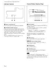
... blinks green. Location and Function of Parts and Controls Indicator Section Control Button Section (Top) 12 12345 6 1 Remote control detector Receives the signals from the Remote Commander. 2 POWER/STANDBY indicator Lights up in orange when the display enters the power saving mode while a signal is input from the INPUT or OPTION connector. Lights up in red in the standby mode. Press again to hide them. 3 4 m/M (cursor/volume) button Press to move the cursor (yellow), set a value, or control speaker volume. 5 ENTER button...
... blinks green. Location and Function of Parts and Controls Indicator Section Control Button Section (Top) 12 12345 6 1 Remote control detector Receives the signals from the Remote Commander. 2 POWER/STANDBY indicator Lights up in orange when the display enters the power saving mode while a signal is input from the INPUT or OPTION connector. Lights up in red in the standby mode. Press again to hide them. 3 4 m/M (cursor/volume) button Press to move the cursor (yellow), set a value, or control speaker volume. 5 ENTER button...
Operating Instructions
Page 9
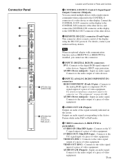
.... Outputs an audio signal corresponding to the Active Picture while in the P&P or PinP mode. 6 VIDEO connectors (A BKM-FW10 is installed, you cannot use this display to the CONTROL S IN connector of the other device, and connect the CONTROL S IN connector on page 44 (GB). Connects to the audio output of a piece of video equipment. 5 AUDIO OUT L/R (Pinjack) Outputs an audio of video equipment. IN CONTROL S OUT REMOTE Connector Panel 1 2 3 4 5 DVI-HDCP INPUT 1 AUDIO RGB/COMPONENT INPUT 2 AUDIO L AUDIO...
.... Outputs an audio signal corresponding to the Active Picture while in the P&P or PinP mode. 6 VIDEO connectors (A BKM-FW10 is installed, you cannot use this display to the CONTROL S IN connector of the other device, and connect the CONTROL S IN connector on page 44 (GB). Connects to the audio output of a piece of video equipment. 5 AUDIO OUT L/R (Pinjack) Outputs an audio of video equipment. IN CONTROL S OUT REMOTE Connector Panel 1 2 3 4 5 DVI-HDCP INPUT 1 AUDIO RGB/COMPONENT INPUT 2 AUDIO L AUDIO...
Operating Instructions
Page 10
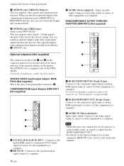
... 3 AUDIO (Stereo minijack) : Inputs an audio signal. When you install an optional adaptor with video signal input/ output function into this slot, you can be fitted with communication function should be installed in types and can control the display unit via the network. 8 OPTION2 slot (VIDEO port) (Only for the FWD-40LX1) This slot supports video signals. Optional adaptors (Not supplied) The connectors marked with 7 and 8 on the Option Adaptors for the factory setting...
... 3 AUDIO (Stereo minijack) : Inputs an audio signal. When you install an optional adaptor with video signal input/ output function into this slot, you can be fitted with communication function should be installed in types and can control the display unit via the network. 8 OPTION2 slot (VIDEO port) (Only for the FWD-40LX1) This slot supports video signals. Optional adaptors (Not supplied) The connectors marked with 7 and 8 on the Option Adaptors for the factory setting...
Operating Instructions
Page 11
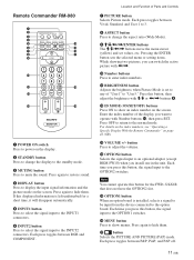
... the signal input to the INPUT1 connectors. 6 INPUT2 button Press to select the signal input to display the input signal information and the picture mode on the display. 2 STANDBY button Press to change the aspect ratio (Wide Mode). 9 M/m/ Remote Commander RM-980 1 2 MUTING DISPLAY STBY ON 3 4 5 qf 6 qg 7 qh 8 qj 9 ENTER 123 0 456 789 qa 0 qk qs ON SET qd ql MONITOR RM-980 1 POWER ON switch Press to power on the screen.
... the signal input to the INPUT1 connectors. 6 INPUT2 button Press to select the signal input to display the input signal information and the picture mode on the display. 2 STANDBY button Press to change the aspect ratio (Wide Mode). 9 M/m/ Remote Commander RM-980 1 2 MUTING DISPLAY STBY ON 3 4 5 qf 6 qg 7 qh 8 qj 9 ENTER 123 0 456 789 qa 0 qk qs ON SET qd ql MONITOR RM-980 1 POWER ON switch Press to power on the screen.
Operating Instructions
Page 12
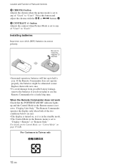
Press this button and adjust the chroma with the M/m or Location and Function of Parts and Controls qk CHROMA button Adjusts the chroma when the picture mode is set to any of "User1" to "User3."
Press this button and adjust the chroma with the M/m or Location and Function of Parts and Controls qk CHROMA button Adjusts the chroma when the picture mode is set to any of "User1" to "User3."
Operating Instructions
Page 15
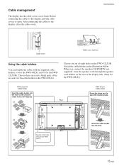
... connecting the cables to open the hooking nails. 2 Speaker cord holder (Only for the FWD32LX1R). When you connect the speakers SS-SP40FW (not supplied), route the speaker cords through the speaker cord holders on the rear of the display unit. (Only for the cable holder on its back. Choose three successive blank parts of eight holes on the unit and rotate it about 90 degrees. 1 Rear FWD-40LX1 Cable holder...
... connecting the cables to open the hooking nails. 2 Speaker cord holder (Only for the FWD32LX1R). When you connect the speakers SS-SP40FW (not supplied), route the speaker cords through the speaker cord holders on the rear of the display unit. (Only for the cable holder on its back. Choose three successive blank parts of eight holes on the unit and rotate it about 90 degrees. 1 Rear FWD-40LX1 Cable holder...
Operating Instructions
Page 16
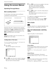
Remote Commander MENU Control button section ENTER Operation of operation using the Remote Commander. Using On-screen Menus Using On-screen Menus Operating Through Menus Menu operating buttons Use the buttons on the display. Note Operation may differ in these operating instructions for menu operations. The M/m and ENTER buttons on the Remote Commander have the same functions as the M/m and ENTER buttons on the display unit or the Remote Commander for the case of the unit is explained in some cases since there is no
Remote Commander MENU Control button section ENTER Operation of operation using the Remote Commander. Using On-screen Menus Using On-screen Menus Operating Through Menus Menu operating buttons Use the buttons on the display. Note Operation may differ in these operating instructions for menu operations. The M/m and ENTER buttons on the Remote Commander have the same functions as the M/m and ENTER buttons on the display unit or the Remote Commander for the case of the unit is explained in some cases since there is no
Operating Instructions
Page 17
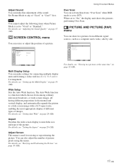
..., see "Resizing and Positioning the Picture" on page 28 (GB). For details, see "Setting Auto Wide" on page 30 (GB). Using On-screen Menus Over Scan You can make fine adjustment of the sound. Adjust Sound You can also adjust the number of picture pixels using this menu. Wide Setup Sets the Auto Wide function. When set to any of the picture. Set Picture Mode to "On," the display unit shows the pictures performing Over...
..., see "Resizing and Positioning the Picture" on page 28 (GB). For details, see "Setting Auto Wide" on page 30 (GB). Using On-screen Menus Over Scan You can make fine adjustment of the sound. Adjust Sound You can also adjust the number of picture pixels using this menu. Wide Setup Sets the Auto Wide function. When set to any of the picture. Set Picture Mode to "On," the display unit shows the pictures performing Over...
Operating Instructions
Page 18
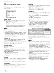
... connected to a PC. Notes • "Power Saving: Reduce" will not be selected. CUSTOM SETUP Power Saving: Speaker Out: Closed Caption: Display: Color Matrix HD Mode: RGB Mode Sync Mode: Illumination: Remote Standard Off Off Off 1080i H/Comp High Select Set ENTER Exit MENU Power Saving Reduces power consumption while showing pictures. Color Matrix Sets the Color Matrix to show pictures in natural color tones when a component signal is not displayed. H/Comp: When a horizontal signal is input Video: When a video signal is input...
... connected to a PC. Notes • "Power Saving: Reduce" will not be selected. CUSTOM SETUP Power Saving: Speaker Out: Closed Caption: Display: Color Matrix HD Mode: RGB Mode Sync Mode: Illumination: Remote Standard Off Off Off 1080i H/Comp High Select Set ENTER Exit MENU Power Saving Reduces power consumption while showing pictures. Color Matrix Sets the Color Matrix to show pictures in natural color tones when a component signal is not displayed. H/Comp: When a horizontal signal is input Video: When a video signal is input...
Operating Instructions
Page 19
... using the control buttons on when a signal is installed into the OPTION1 slot. Using On-screen Menus INITIAL SETUP/INFORMATION menu You can select the on the display unit for more than about five minutes. Auto: to the DVI or RGB input connectors for setting, you want to switch the display unit on the front of the display unit. The index number cannot be set this item, the modes...
... using the control buttons on when a signal is installed into the OPTION1 slot. Using On-screen Menus INITIAL SETUP/INFORMATION menu You can select the on the display unit for more than about five minutes. Auto: to the DVI or RGB input connectors for setting, you want to switch the display unit on the front of the display unit. The index number cannot be set this item, the modes...

Operating Instructions
Page 20
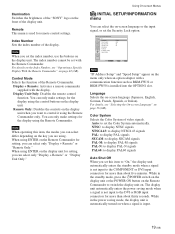
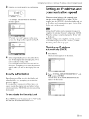
Using On-screen Menus Security Lock Sets the security lock on /off . For details, see "Setting an IP Address and communication speed" on the menu only when an option adaptor with a communication function such as part of the Operation Time. INITIAL SETUP/INFORMATION Information Model Name: Serial Number: Operation Time: Software Version: IP Address: Select Set ENTER Exit MENU Note "IP Address" appears on page 39 (GB). All Reset Resets all the...
Using On-screen Menus Security Lock Sets the security lock on /off . For details, see "Setting an IP Address and communication speed" on the menu only when an option adaptor with a communication function such as part of the Operation Time. INITIAL SETUP/INFORMATION Information Model Name: Serial Number: Operation Time: Software Version: IP Address: Select Set ENTER Exit MENU Note "IP Address" appears on page 39 (GB). All Reset Resets all the...
Operating Instructions
Page 21
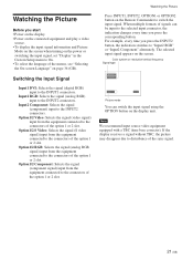
... connected equipment and play a video source. • To display the input signal information and Picture Mode on the screen when turning on the power or switching the input signal, set "Display" in the Custom Setup menu to On. • To select the language of the option 1 or 2 slot. Option1/2 Video: Selects the signal (video signal) input from the equipment connected to the connectors of signals can switch the input signal using the OPTION button on the screen. Option1/2 RGB: Selects the signal (analog RGB signal) input...
... connected equipment and play a video source. • To display the input signal information and Picture Mode on the screen when turning on the power or switching the input signal, set "Display" in the Custom Setup menu to On. • To select the language of the option 1 or 2 slot. Option1/2 Video: Selects the signal (video signal) input from the equipment connected to the connectors of signals can switch the input signal using the OPTION button on the screen. Option1/2 RGB: Selects the signal (analog RGB signal) input...
Operating Instructions
Page 33
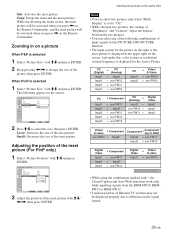
Sub: Activates the inset picture. While not showing the menu screen, the main picture will be activated when you press < on the Remote Commander, and the inset picture will be activated when you press , on a picture When P&P is selected 1 Select "Picture Size" with M/m and press ENTER. 2 Keep pressing Swap: Swaps the main and the inset pictures. Zooming in on the Remote Commander.
Sub: Activates the inset picture. While not showing the menu screen, the main picture will be activated when you press < on the Remote Commander, and the inset picture will be activated when you press , on a picture When P&P is selected 1 Select "Picture Size" with M/m and press ENTER. 2 Keep pressing Swap: Swaps the main and the inset pictures. Zooming in on the Remote Commander.
Operating Instructions
Page 39
... switch to turn off the display unit and unplug the power cord to make the setting valid. In such a situation, confirm the setting values and set "Security Lock" to "Off" in the display unit, set for re-confirmation. Select Set ENTER Exit MENU 4 After completing the process described above, turn on the menu screen, start the procedure again from Step 1. PICTURE/SOUND CONTROL Picture Mode: Vivid Adjust Picture Adjust Sound Select Set ENTER Exit MENU 2 Select "INITIAL SETUP...
... switch to turn off the display unit and unplug the power cord to make the setting valid. In such a situation, confirm the setting values and set "Security Lock" to "Off" in the display unit, set for re-confirmation. Select Set ENTER Exit MENU 4 After completing the process described above, turn on the menu screen, start the procedure again from Step 1. PICTURE/SOUND CONTROL Picture Mode: Vivid Adjust Picture Adjust Sound Select Set ENTER Exit MENU 2 Select "INITIAL SETUP...
Operating Instructions
Page 40
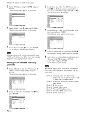
... speed 3 Select "IP Address Setup" with M/m, then press ENTER. Setting an IP address manually (Manual) 1 Select "Manual" in accordance with the error cause. Note When you obtain an IP address automatically using DHCP, an IP address may differ every time you turn the power of the display unit off and on the screen. The cursor moves to be set for each of "Obtaining...
... speed 3 Select "IP Address Setup" with M/m, then press ENTER. Setting an IP address manually (Manual) 1 Select "Manual" in accordance with the error cause. Note When you obtain an IP address automatically using DHCP, an IP address may differ every time you turn the power of the display unit off and on the screen. The cursor moves to be set for each of "Obtaining...
Operating Instructions
Page 43
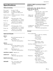
Specifications Video processing Preset signal See page 23 (GB). Sampling rate 13.5 MHz to 140 MHz Panel system a-Si TFT Active Matrix LCD Panel Display resolution 1366 dots (horizontal) × 768 lines (vertical) FWD-40LX1: Pixel pitch 0.648 (horizontal) × 0.648 (vertical) mm (1⁄32 × 1⁄32 inches) Picture size 885 (horizontal) × 498 (vertical) mm (34 7⁄8 × 19 5⁄8 inches) Panel size 40-inch (diagonal 1016...
Specifications Video processing Preset signal See page 23 (GB). Sampling rate 13.5 MHz to 140 MHz Panel system a-Si TFT Active Matrix LCD Panel Display resolution 1366 dots (horizontal) × 768 lines (vertical) FWD-40LX1: Pixel pitch 0.648 (horizontal) × 0.648 (vertical) mm (1⁄32 × 1⁄32 inches) Picture size 885 (horizontal) × 498 (vertical) mm (34 7⁄8 × 19 5⁄8 inches) Panel size 40-inch (diagonal 1016...


