
Installation
Page 1
...Install the system following steps. 1. JOINT TOP AND BOTTOM CABINETS 4. SETUP PROJECTION MIRROR 5. ADJUST PROJECTION MIRROR 6. AND NEVER TOUCH THE SURFACE OF THE PROJECTION SCREEN AND THE PROJECTION MIRROR DIRECTLY. This system is missing, or if you have questions, ...CONTACT A SERVICE. Rear Projection Display Installation Manual REQUEST A SALES DEALER FOR INSTALLATION Please read "SAFETY PRECAUTIONS" and "IMPORTANT SAFETY INSTRUCTIONS" on OWNER'S MANUAL to be installed. THEY MAY EFFECT THE PROJECTION IMAGE QUALITY. EXCEPT WHEN ADJUSTING THE PROJECTION MIRROR, NEVER TURN...
...Install the system following steps. 1. JOINT TOP AND BOTTOM CABINETS 4. SETUP PROJECTION MIRROR 5. ADJUST PROJECTION MIRROR 6. AND NEVER TOUCH THE SURFACE OF THE PROJECTION SCREEN AND THE PROJECTION MIRROR DIRECTLY. This system is missing, or if you have questions, ...CONTACT A SERVICE. Rear Projection Display Installation Manual REQUEST A SALES DEALER FOR INSTALLATION Please read "SAFETY PRECAUTIONS" and "IMPORTANT SAFETY INSTRUCTIONS" on OWNER'S MANUAL to be installed. THEY MAY EFFECT THE PROJECTION IMAGE QUALITY. EXCEPT WHEN ADJUSTING THE PROJECTION MIRROR, NEVER TURN...
Installation
Page 2
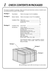
... some models. Make sure all the parts listed below (cabinets, Installation parts, and accessories) are included in 3 packages. Package 2 Bottom Cabinet : Refer to the Owner's Manual for installation. Center Panel 1 Owner's Manual 1 Installation Manual (this figure in some models. Package 1 Top Cabinet : Refer to the steps 3 to 6 for details.
... some models. Make sure all the parts listed below (cabinets, Installation parts, and accessories) are included in 3 packages. Package 2 Bottom Cabinet : Refer to the Owner's Manual for installation. Center Panel 1 Owner's Manual 1 Installation Manual (this figure in some models. Package 1 Top Cabinet : Refer to the steps 3 to 6 for details.
Installation
Page 6
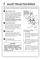
... turning the Adjusting Nuts. Refer to the figure on the Projection Screen and is not distorted. (Refer to the Owner's Manual for the image movement with the Adjusting Nut. 3 Fix Projection Mirror Fix the Projection Mirror where the picture is stretched. Mirror Arm Adjusting Nut ...WHEN ADJUSTING THE MIRROR, NEVER TOUCH THE PARTS EXCEPT THE MIRROR. Skip the steps below . Mirror Holder Screw(B) 2 Adjust Projection Mirror Adjust the Projection Mirror by turning the Adjusting Nuts on both sides to 4. Adjust Screw(B) if it should happen, readjust the Mirror following the...
... turning the Adjusting Nuts. Refer to the figure on the Projection Screen and is not distorted. (Refer to the Owner's Manual for the image movement with the Adjusting Nut. 3 Fix Projection Mirror Fix the Projection Mirror where the picture is stretched. Mirror Arm Adjusting Nut ...WHEN ADJUSTING THE MIRROR, NEVER TOUCH THE PARTS EXCEPT THE MIRROR. Skip the steps below . Mirror Holder Screw(B) 2 Adjust Projection Mirror Adjust the Projection Mirror by turning the Adjusting Nuts on both sides to 4. Adjust Screw(B) if it should happen, readjust the Mirror following the...
Owners Manual
Page 2
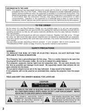
...APPLIANCE TO RAIN OR MOISTURE. This projector should not be sure that the plug will be used in accordance with the instruction manual, may result in which case the user will fit into the beam. NO USER-SERVICEABLE PARTS INSIDE EXCEPT LAMP REPLACEMENT. If...can often correct operating problems yourself. Operation of a new Rear-Projection Display, you are designed to provide reasonable protection against harmful interference when the equipment is likely to cause harmful interference in fire hazard. This owner's manual will help us too. Reading it will acquaint you with...
...APPLIANCE TO RAIN OR MOISTURE. This projector should not be sure that the plug will be used in accordance with the instruction manual, may result in which case the user will fit into the beam. NO USER-SERVICEABLE PARTS INSIDE EXCEPT LAMP REPLACEMENT. If...can often correct operating problems yourself. Operation of a new Rear-Projection Display, you are designed to provide reasonable protection against harmful interference when the equipment is likely to cause harmful interference in fire hazard. This owner's manual will help us too. Reading it will acquaint you with...
Owners Manual
Page 4
... CONNECTION 40 SOUND ADJUSTMENT 25 MAINTENANCE 41 PICTURE FREEZE FUNCTION 25 TROUBLESHOOTING 43 TECHNICAL SPECIFICATIONS 44 l Each name of corporations or products in the owner's manual is a trademark or a registered trademark of its respective corporation. 4
... CONNECTION 40 SOUND ADJUSTMENT 25 MAINTENANCE 41 PICTURE FREEZE FUNCTION 25 TROUBLESHOOTING 43 TECHNICAL SPECIFICATIONS 44 l Each name of corporations or products in the owner's manual is a trademark or a registered trademark of its respective corporation. 4

Owners Manual
Page 5
...to 1280 ´ 1024 resolution. u Accessories This projector comes with large screen. l Owner's Manual l Installation Manual l AC Power Cord l Wireless Remote Control Unit l Wired/Wireless Remote Control Unit l Remote .... l Various VCRs, video disc players, video cameras, DVD players, satellite TV tuners or other AV equipment using any parts are missing, contact to a lower... Image is projected in multimedia features, a palette of 1024 x 768. l Apple Macintosh and PowerBook computers up to produce high quality sound. FEATURES AND DESIGN This Multimedia Rear-Projection Display is ...
...to 1280 ´ 1024 resolution. u Accessories This projector comes with large screen. l Owner's Manual l Installation Manual l AC Power Cord l Wireless Remote Control Unit l Wired/Wireless Remote Control Unit l Remote .... l Various VCRs, video disc players, video cameras, DVD players, satellite TV tuners or other AV equipment using any parts are missing, contact to a lower... Image is projected in multimedia features, a palette of 1024 x 768. l Apple Macintosh and PowerBook computers up to produce high quality sound. FEATURES AND DESIGN This Multimedia Rear-Projection Display is ...
Owners Manual
Page 6
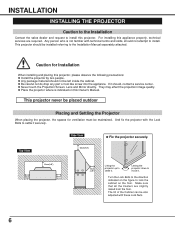
... who is indicated on this projector. l Be careful not do drop any part or tool like screw into the appliance. They may effect the projection image quality. Top View Side View 20cm(7.8") u Fix the projector securely. 20cm (7.8") 10cm(3.9") 20cm (7.8") 10cm (3.9") Lifting the projector up to... . This projector should not be maintained. Turn the Lock Bolts to the direction indicated on the figure to install this Owner's Manual. Make sure that all the Casters are required. This projector never be placed outdoor Placing and Settling the Projector When placing the projector...
... who is indicated on this projector. l Be careful not do drop any part or tool like screw into the appliance. They may effect the projection image quality. Top View Side View 20cm(7.8") u Fix the projector securely. 20cm (7.8") 10cm(3.9") 20cm (7.8") 10cm (3.9") Lifting the projector up to... . This projector should not be maintained. Turn the Lock Bolts to the direction indicated on the figure to install this Owner's Manual. Make sure that all the Casters are required. This projector never be placed outdoor Placing and Settling the Projector When placing the projector...
Owners Manual
Page 27
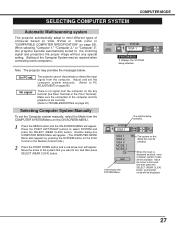
...VGA, SVGA or XGA (refer to "COMPATIBLE COMPUTER SPECIFICATION" on page 28). The system being selected. Adjust and set the computer system manually. (Refer to PC ADJUSTMENT on page 28.) There is displayed as black, more computer system modes will be displayed. 27 When this... input signal from the computer. Press the POINT LEFT/RIGHT buttons to the incoming signal and projectors the proper image without any terminal (the Rear Terminal or the Front Terminal). When selecting "Computer 1," "Computer 2," or "Computer 3", this dialog box can be required when connecting some ...
...VGA, SVGA or XGA (refer to "COMPATIBLE COMPUTER SPECIFICATION" on page 28). The system being selected. Adjust and set the computer system manually. (Refer to PC ADJUSTMENT on page 28.) There is displayed as black, more computer system modes will be displayed. 27 When this... input signal from the computer. Press the POINT LEFT/RIGHT buttons to the incoming signal and projectors the proper image without any terminal (the Rear Terminal or the Front Terminal). When selecting "Computer 1," "Computer 2," or "Computer 3", this dialog box can be required when connecting some ...
Owners Manual
Page 28
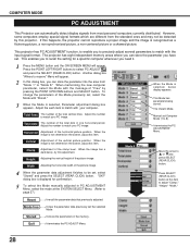
.../DOWN buttons and SELECT button. This enables you to recall the setting for confirmation. 5 To select the Mode manually adjusted in the memory. Adjust the number to 8). Manual set Computer Mode (1 to match your PC image. Adjusting the vertical height of the total vertical lines. Another dialog...not centered on the screen, adjust this item to match your PC image. Adjust the each item to select PC ADJUST and press the SELECT (REAR CLICK) button. Stored Stored Stored When the Mode is recognized as a flickering picture, a non-synchronized picture, a non-centered picture or a...
.../DOWN buttons and SELECT button. This enables you to recall the setting for confirmation. 5 To select the Mode manually adjusted in the memory. Adjust the number to 8). Manual set Computer Mode (1 to match your PC image. Adjusting the vertical height of the total vertical lines. Another dialog...not centered on the screen, adjust this item to match your PC image. Adjust the each item to select PC ADJUST and press the SELECT (REAR CLICK) button. Stored Stored Stored When the Mode is recognized as a flickering picture, a non-synchronized picture, a non-centered picture or a...

Owners Manual
Page 30
...(From 0 to 63.) Brightness Point to to adjust the image darker, and select to adjust the image brighter. (From 0 to and then press the SELECT (REAR CLICK) button. It indicates the roughly level of the total dots in the memory. Total Dots The number of the item. Another dialog box PICTURE...POINT UP/DOWN buttons. Fine sync Adjust the picture as necessary to eliminate flicker from the display. (From 0 to select IMAGE and press the SELECT (REAR CLICK) button. COMPUTER MODE PICTURE IMAGE ADJUSTMENT Adjust Picture Image Manually 1 Press the MENU button and the ON-SCREEN MENU will appear.
...(From 0 to 63.) Brightness Point to to adjust the image darker, and select to adjust the image brighter. (From 0 to and then press the SELECT (REAR CLICK) button. It indicates the roughly level of the total dots in the memory. Total Dots The number of the item. Another dialog box PICTURE...POINT UP/DOWN buttons. Fine sync Adjust the picture as necessary to eliminate flicker from the display. (From 0 to select IMAGE and press the SELECT (REAR CLICK) button. COMPUTER MODE PICTURE IMAGE ADJUSTMENT Adjust Picture Image Manually 1 Press the MENU button and the ON-SCREEN MENU will appear.
Owners Manual
Page 31
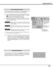
and press the SELECT (REAR CLICK) button to eliminate flicker from the display. or "Total dots" and PICTURE POSITION ADJUSTMENT on page 30 to adjust "Fine sync." Fine sync Adjust the picture as necessary to start the Auto Image function. This item can be adjusted manually. (Refer to page 32.) 3 ...Move the arrow to "Go!" In that you want to adjust by pressing the POINT UP/DOWN button. COMPUTER MODE Move the arrow to select AUTO IMAGE and press the SELECT (REAR CLICK) button. It terminates the PICTURE ...
and press the SELECT (REAR CLICK) button to eliminate flicker from the display. or "Total dots" and PICTURE POSITION ADJUSTMENT on page 30 to adjust "Fine sync." Fine sync Adjust the picture as necessary to start the Auto Image function. This item can be adjusted manually. (Refer to page 32.) 3 ...Move the arrow to "Go!" In that you want to adjust by pressing the POINT UP/DOWN button. COMPUTER MODE Move the arrow to select AUTO IMAGE and press the SELECT (REAR CLICK) button. It terminates the PICTURE ...

Owners Manual
Page 35
...MENU will appear. Press the POINT LEFT/RIGHT buttons to select SYSTEM and press the SELECT (REAR CLICK) button. When connecting to those equipment, select the type of Video source in VIDEO SOURCE... being selected. When the Video System is required to "Auto", and then press the SELECT (REAR CLICK) button. Move the arrow to the system that you want to optimize its performance. Another... reproduce the proper video image, it is PAL-M or PAL-N, select the system manually. Another dialog box VIDEO SOURCE Menu will appear. 2 Press the POINT DOWN button and a red-arrow icon will...
...MENU will appear. Press the POINT LEFT/RIGHT buttons to select SYSTEM and press the SELECT (REAR CLICK) button. When connecting to those equipment, select the type of Video source in VIDEO SOURCE... being selected. When the Video System is required to "Auto", and then press the SELECT (REAR CLICK) button. Move the arrow to the system that you want to optimize its performance. Another... reproduce the proper video image, it is PAL-M or PAL-N, select the system manually. Another dialog box VIDEO SOURCE Menu will appear. 2 Press the POINT DOWN button and a red-arrow icon will...
Owners Manual
Page 44
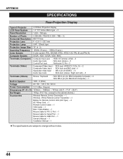
...Size Scanning Frequency Color System Computer System Terminals (Computer) Terminals (Video) LCD Rear-Projection Display 1.3" TFT Active Matrix type ´ 3 1,024 ´ 768 dots 2,359,296 ( 786,432 {1,024 ´ 768} ´ 3 ) 800 TV lines F = 2.5 / f = 23.7 mm UHP, 120watt type 70" (4 : 3) ~80kHz (H-sync.), ~100Hz (V-sync.) 6 color system ... Accessories Mouse / Keyboard : Mini DIN 6 pin (for IBM-Compatible Computer) ´ 2 Mini DIN 4 pin (for ADB Port ´ 1 Owner's Manual ´ 1 Installation Manual ´ 1 l The specifications are subject to change without notice. 44
...Size Scanning Frequency Color System Computer System Terminals (Computer) Terminals (Video) LCD Rear-Projection Display 1.3" TFT Active Matrix type ´ 3 1,024 ´ 768 dots 2,359,296 ( 786,432 {1,024 ´ 768} ´ 3 ) 800 TV lines F = 2.5 / f = 23.7 mm UHP, 120watt type 70" (4 : 3) ~80kHz (H-sync.), ~100Hz (V-sync.) 6 color system ... Accessories Mouse / Keyboard : Mini DIN 6 pin (for IBM-Compatible Computer) ´ 2 Mini DIN 4 pin (for ADB Port ´ 1 Owner's Manual ´ 1 Installation Manual ´ 1 l The specifications are subject to change without notice. 44
Owners Manual
Page 46
... the user's expense, unless specifically stated otherwise in this SANYO product against defects in the appropriate model's instruction manual, or (B) the repair of this warranty. the names and addresses of authorized Sanyo Service Centers may be delivered to and picked up from ...Chatsworth, California 91311 Where Purchased Printed in the information below for your protection in lieu of LABOR and PARTS specified below , SANYO FISHER COMPANY (SFC) warrants this warranty. For product operation, authorized service center referral, service assistance or problem resolution, call ...
... the user's expense, unless specifically stated otherwise in this SANYO product against defects in the appropriate model's instruction manual, or (B) the repair of this warranty. the names and addresses of authorized Sanyo Service Centers may be delivered to and picked up from ...Chatsworth, California 91311 Where Purchased Printed in the information below for your protection in lieu of LABOR and PARTS specified below , SANYO FISHER COMPANY (SFC) warrants this warranty. For product operation, authorized service center referral, service assistance or problem resolution, call ...