Owners Manual
Page 4
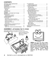
...PC Menu Operating Tips 11 Manual Adjustments 11 ON-SCREEN MENU OPERATION- screen LCD HDTV. Precautions 5 Remote Control Battery Installation 5 Antenna Connections to Scan Memory 13 Deleting Channels from stand mounting inserts [D] before installing stand base.) Padded Surface Hello! HDMI 1 / 2 10 Digital Audio / Audio...Visit our Web site at www.sanyoctv.com or Call 1-800-877-5032 I'm your new Sanyo Wide- Handling 3 Disposal 3 SPECIFICATIONS 3 CONTENTS 4 ASSEMBLY-ATTACHING THE TV STAND 4 INSTALLATION- Menu Navigation Map 12 Manual Channel Search 12 Channel Scan Memory 13 Adding...
...PC Menu Operating Tips 11 Manual Adjustments 11 ON-SCREEN MENU OPERATION- screen LCD HDTV. Precautions 5 Remote Control Battery Installation 5 Antenna Connections to Scan Memory 13 Deleting Channels from stand mounting inserts [D] before installing stand base.) Padded Surface Hello! HDMI 1 / 2 10 Digital Audio / Audio...Visit our Web site at www.sanyoctv.com or Call 1-800-877-5032 I'm your new Sanyo Wide- Handling 3 Disposal 3 SPECIFICATIONS 3 CONTENTS 4 ASSEMBLY-ATTACHING THE TV STAND 4 INSTALLATION- Menu Navigation Map 12 Manual Channel Search 12 Channel Scan Memory 13 Adding...
Service Manual
Page 1
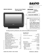
... 45.75MHz SOUND IF CARRIER 41.25MHz COLOR SUB CARRIEr 42.17MHz CABINET DIMENSIONS WIDTH 665.5mm HEIGHT 515.6mm DEPTH INCLUDING BASE 177.8mm © Sanyo Manufacturing Corporation 2008 DP26648, N6CE, PRODUCT CODE 113013904 REFERENCE No. P26648-00 NOTE: Match the Chassis No. If the Original Version Service Manual Chassis No. Servicing...
... 45.75MHz SOUND IF CARRIER 41.25MHz COLOR SUB CARRIEr 42.17MHz CABINET DIMENSIONS WIDTH 665.5mm HEIGHT 515.6mm DEPTH INCLUDING BASE 177.8mm © Sanyo Manufacturing Corporation 2008 DP26648, N6CE, PRODUCT CODE 113013904 REFERENCE No. P26648-00 NOTE: Match the Chassis No. If the Original Version Service Manual Chassis No. Servicing...
Service Manual
Page 7
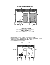
Disconnect the lead wires from the front cabinet. -7- Once you have taken off the Lid back, stand base, power unit and main board remove 9 screws (C:3X14) and 4 screws (D:4X8) to take the back cabinet off LCD panel removal Removal 1. POWER AND MAIN BOARD REMOVAL 1: Main Board Removal Remove 5 screws (3X14) to take the main board off. 2: Power Unit Removal Remove 6 screws (3X14) to take the power unit off . 3. Lift the LCD panel from LCD panel, speakers, and control board. 2.
Disconnect the lead wires from the front cabinet. -7- Once you have taken off the Lid back, stand base, power unit and main board remove 9 screws (C:3X14) and 4 screws (D:4X8) to take the back cabinet off LCD panel removal Removal 1. POWER AND MAIN BOARD REMOVAL 1: Main Board Removal Remove 5 screws (3X14) to take the main board off. 2: Power Unit Removal Remove 6 screws (3X14) to take the power unit off . 3. Lift the LCD panel from LCD panel, speakers, and control board. 2.

Service Manual
Page 53
COLLECTOR E ... BASE C ... BASE C ... EMITTER B CE K A K A INFRARED EMITTING A....ANODE K....CATHODE CHIP TRANSISTORS CHIP RESISTORS TOP VIEW C B ... EMITTER TOP VIEW 12 x 10 3 = 12K ohm 123 BE - 53 - COLLECTOR E ... IC, DIODE, AND TRANSISTOR PIN LAYOUTS INTEGRATED CIRCUITS TOP VIEW MARK 1 COUNT TERMINALS IN ARROW DIRECTION SIDE VIEW 1 1 PHOTO COUPLERS TOP VIEW 1 1 1 1 1 123 1 32 OUT IN (1) GND (2) (3) TRANSISTORS DIODES E CB E CB B EC E CB B EC A K A K A K A K CE B BCE B E C B ...
COLLECTOR E ... BASE C ... BASE C ... EMITTER B CE K A K A INFRARED EMITTING A....ANODE K....CATHODE CHIP TRANSISTORS CHIP RESISTORS TOP VIEW C B ... EMITTER TOP VIEW 12 x 10 3 = 12K ohm 123 BE - 53 - COLLECTOR E ... IC, DIODE, AND TRANSISTOR PIN LAYOUTS INTEGRATED CIRCUITS TOP VIEW MARK 1 COUNT TERMINALS IN ARROW DIRECTION SIDE VIEW 1 1 PHOTO COUPLERS TOP VIEW 1 1 1 1 1 123 1 32 OUT IN (1) GND (2) (3) TRANSISTORS DIODES E CB E CB B EC E CB B EC A K A K A K A K CE B BCE B E C B ...


