

Owners Manual
Page 2
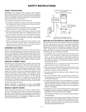
...? Install in particular, specifies that produce heat. 9. A grounding-type plug has two blades and a third grounding prong. Protect the power cord from touching such power lines or circuits as to rain or moisture, does not operate normally, or has been dropped. 15. Selection 810-21 of the obsolete...FIRE OR ELECTRIC SHOCK, DO NOT EXPOSE THIS APPLIANCE TO RAIN OR MOISTURE. Clean only with one wider than the other electrical light or power circuits, or where it can fall into your safety. Do not use attachments/accessories specified by the manufacturer, or sold with the manufacturer...
...? Install in particular, specifies that produce heat. 9. A grounding-type plug has two blades and a third grounding prong. Protect the power cord from touching such power lines or circuits as to rain or moisture, does not operate normally, or has been dropped. 15. Selection 810-21 of the obsolete...FIRE OR ELECTRIC SHOCK, DO NOT EXPOSE THIS APPLIANCE TO RAIN OR MOISTURE. Clean only with one wider than the other electrical light or power circuits, or where it can fall into your safety. Do not use attachments/accessories specified by the manufacturer, or sold with the manufacturer...
Owners Manual
Page 3
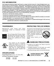
...Power Consumption (average): CONTAINS MERCURY LAMPS, DISPOSE OF PROPERLY DP26648 DP32648 120 watts 160 watts Need help . Visit our Web site at www.sanyoctv.com or Call 1-800-877-5032 3 These limits are designed to provide reasonable protection against risk of the FCC Rules. PROTECTING THE LCD...relocate the receiving antenna. - "As an Energy Star® Partner, Sanyo Manufacturing Corporation has determined that to meet rigid U.L. HANDLING PRECAUTIONS •... Laboratories. Consult the dealer or an experienced radio/TV technician for a Class B digital device, pursuant to operate ...
...Power Consumption (average): CONTAINS MERCURY LAMPS, DISPOSE OF PROPERLY DP26648 DP32648 120 watts 160 watts Need help . Visit our Web site at www.sanyoctv.com or Call 1-800-877-5032 3 These limits are designed to provide reasonable protection against risk of the FCC Rules. PROTECTING THE LCD...relocate the receiving antenna. - "As an Energy Star® Partner, Sanyo Manufacturing Corporation has determined that to meet rigid U.L. HANDLING PRECAUTIONS •... Laboratories. Consult the dealer or an experienced radio/TV technician for a Class B digital device, pursuant to operate ...
Owners Manual
Page 4
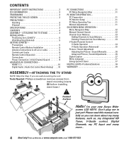
I'm your new Sanyo Wide- Don't plug me in just yet! Visit our Web site at www.sanyoctv.com or Call 1-800-877-5032 CONTENTS IMPORTANT SAFETY INSTRUCTIONS 2 FCC INFORMATION 3 TRADEMARKS 3 PROTECTING THE LCD SCREEN 3 PRECAUTIONS- Tools Needed: Phillips screwdriver (remove screws from Scan Memory ...Sound Manually 16 Advanced Picture / Sound Adjustments 16 Digital Caption 17 Menu Language 17 Energy (power) Saver 17 HELPFUL HINTS-Problems/Solutions 18 WARRANTY 19 ASSEMBLY-ATTACHING THE TV STAND NOTE: Skip this manual carefully so you are wall-mounting the unit. Precautions 5 ...
I'm your new Sanyo Wide- Don't plug me in just yet! Visit our Web site at www.sanyoctv.com or Call 1-800-877-5032 CONTENTS IMPORTANT SAFETY INSTRUCTIONS 2 FCC INFORMATION 3 TRADEMARKS 3 PROTECTING THE LCD SCREEN 3 PRECAUTIONS- Tools Needed: Phillips screwdriver (remove screws from Scan Memory ...Sound Manually 16 Advanced Picture / Sound Adjustments 16 Digital Caption 17 Menu Language 17 Energy (power) Saver 17 HELPFUL HINTS-Problems/Solutions 18 WARRANTY 19 ASSEMBLY-ATTACHING THE TV STAND NOTE: Skip this manual carefully so you are wall-mounting the unit. Precautions 5 ...
Owners Manual
Page 6
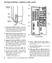
... the Video Green (Y), Blue (Pb), Red (Pr) jacks, and matching Audio White (L ) and Red (R) jacks. GETTING STARTED-CONTROLS AND JACKS Œ RIGHT-SIDE PANEL Power key ’ Ž Volume - + keys Channel ML keys “ Œ S-Video Input (VIDEO1), PAGE 8-To enhance video detail use the S-Video jack instead...
... the Video Green (Y), Blue (Pb), Red (Pr) jacks, and matching Audio White (L ) and Red (R) jacks. GETTING STARTED-CONTROLS AND JACKS Œ RIGHT-SIDE PANEL Power key ’ Ž Volume - + keys Channel ML keys “ Œ S-Video Input (VIDEO1), PAGE 8-To enhance video detail use the S-Video jack instead...
Owners Manual
Page 7
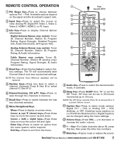
... 99, press this key twice to mute or restore the sound. Visit our Web site at www.sanyoctv.com or Call 1-800-877-5032 7 The TV will be replaced. Number Keys-Press two keys to move the cursor left ) > (right) keys-Press these keys to select a channel. Off time can... be set the Off Timer. NOTE:The Off Timer cancels if the TV is turned off or if a power failure occurs. 11 Caption Key-Press to select mode options: Digital CC1 ~ CC6, or Analog CC1 ~ CC4, QuikCap, or OFF. (QuikCap turns...
... 99, press this key twice to mute or restore the sound. Visit our Web site at www.sanyoctv.com or Call 1-800-877-5032 7 The TV will be replaced. Number Keys-Press two keys to move the cursor left ) > (right) keys-Press these keys to select a channel. Off time can... be set the Off Timer. NOTE:The Off Timer cancels if the TV is turned off or if a power failure occurs. 11 Caption Key-Press to select mode options: Digital CC1 ~ CC6, or Analog CC1 ~ CC4, QuikCap, or OFF. (QuikCap turns...
Owners Manual
Page 9
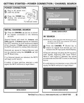
... is detected, the search process ends and the HDTV tunes to the Antenna terminal. INITIAL DISPLAY AV SIGNAL SEARCH DISPLAY Need help? GETTING STARTED-POWER CONNECTION / CHANNEL SEARCH POWER CONNECTION 5 Plug in Channel Memory and can be scanned using the CHANNEL L (Up) and M (Down) keys. Visit our Web site ....sanyoctv.com or Call 1-800-877-5032 9 When a valid signal is not detected on -screen instructions.) To 120V AC outlet. Channels are powered ON before you connected to search for both analog and digital off-air channels. If neither of the AV inputs, the HDTV will tune to...
... is detected, the search process ends and the HDTV tunes to the Antenna terminal. INITIAL DISPLAY AV SIGNAL SEARCH DISPLAY Need help? GETTING STARTED-POWER CONNECTION / CHANNEL SEARCH POWER CONNECTION 5 Plug in Channel Memory and can be scanned using the CHANNEL L (Up) and M (Down) keys. Visit our Web site ....sanyoctv.com or Call 1-800-877-5032 9 When a valid signal is not detected on -screen instructions.) To 120V AC outlet. Channels are powered ON before you connected to search for both analog and digital off-air channels. If neither of the AV inputs, the HDTV will tune to...
Owners Manual
Page 11
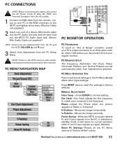
... from the PC and the HDTV VOLUME L and M keys. 3 Select Auto Adjustment from the PC Setup Menu. H-Position-Moves the image horizontally. Power Saving-When the HDTV no longer detects H- PC MENU OPERATING TIPS Picture and Sound settings in the PC Menu do not affect other peripheral equipment ...before you disconnect it switches to an XGA value, such as, 1024 x 768, before powering on your computer's dot frequency. Phase-Adjust the Phase when the picture appears to normal operation when H- and V-sync signals from the PC, it...
... from the PC and the HDTV VOLUME L and M keys. 3 Select Auto Adjustment from the PC Setup Menu. H-Position-Moves the image horizontally. Power Saving-When the HDTV no longer detects H- PC MENU OPERATING TIPS Picture and Sound settings in the PC Menu do not affect other peripheral equipment ...before you disconnect it switches to an XGA value, such as, 1024 x 768, before powering on your computer's dot frequency. Phase-Adjust the Phase when the picture appears to normal operation when H- and V-sync signals from the PC, it...
Owners Manual
Page 17
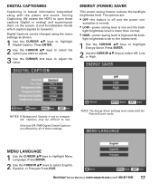
...Digital Captions can be difficult to open these settings. Only true EIA 708B Digital Closed-Captions are : • OFF-the feature is off and the power con- MENU LANGUAGE 1 Use the CURSOR LM keys to select Off, Low, or High. Turning Captioning ON causes the HDTV to see. NOTE: ...The Energy Saver settings level varies with the picture and sound. sumption is normal. • LOW-power saving level is high and the back- Press ENTER. 2 Use the CURSOR LM keys to highlight Menu Language. Press ENTER. 2 Use the CURSOR LM...
...Digital Captions can be difficult to open these settings. Only true EIA 708B Digital Closed-Captions are : • OFF-the feature is off and the power con- MENU LANGUAGE 1 Use the CURSOR LM keys to select Off, Low, or High. Turning Captioning ON causes the HDTV to see. NOTE: ...The Energy Saver settings level varies with the picture and sound. sumption is normal. • LOW-power saving level is high and the back- Press ENTER. 2 Use the CURSOR LM keys to highlight Menu Language. Press ENTER. 2 Use the CURSOR LM...
Service Manual
Page 1
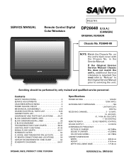
..., DIODE, AND TRANSISTOR PIN LAYOUTS 53 PC BOARD CONNECTIONS AND LOCATIONS 54 CAPACITOR AND RESISTOR CODE CHART 55 SCHEMATIC DIAGRAMS 56-57 Specifications POWER RATING 120VAC 120W (AVG.) ANTENNA INPUT IMPEDANCE 75Ω UHF/VHF/CATV DIGITAL RECEIVING CHANNEL 2 - 13 (VHF), 14 - 69... 665.5mm HEIGHT 515.6mm DEPTH INCLUDING BASE 177.8mm © Sanyo Manufacturing Corporation 2008 DP26648, N6CE, PRODUCT CODE 113013904 REFERENCE No. Servicing should be performed by only trained and qualified service personnel. DP26648 (U.S.A.) (CANADA) ORIGINAL VERSION Chassis No. on the unit's back ...
..., DIODE, AND TRANSISTOR PIN LAYOUTS 53 PC BOARD CONNECTIONS AND LOCATIONS 54 CAPACITOR AND RESISTOR CODE CHART 55 SCHEMATIC DIAGRAMS 56-57 Specifications POWER RATING 120VAC 120W (AVG.) ANTENNA INPUT IMPEDANCE 75Ω UHF/VHF/CATV DIGITAL RECEIVING CHANNEL 2 - 13 (VHF), 14 - 69... 665.5mm HEIGHT 515.6mm DEPTH INCLUDING BASE 177.8mm © Sanyo Manufacturing Corporation 2008 DP26648, N6CE, PRODUCT CODE 113013904 REFERENCE No. Servicing should be performed by only trained and qualified service personnel. DP26648 (U.S.A.) (CANADA) ORIGINAL VERSION Chassis No. on the unit's back ...
Service Manual
Page 2
...prior to the replacement of components marked with a in the parts list and in which requires corrective action. Comply with the receiver power plug reversed. Measure the AC voltage across the two blades. Repeat the above this range indicates an abnormality which the device will ...must be attempted by touching a known earth ground. An isolation transformer must measure between the receiver and the AC line before applying power to static electricity. 3. Before replacing the back cover of the set, thoroughly inspect the inside of fabric together can generate static ...
...prior to the replacement of components marked with a in the parts list and in which requires corrective action. Comply with the receiver power plug reversed. Measure the AC voltage across the two blades. Repeat the above this range indicates an abnormality which the device will ...must be attempted by touching a known earth ground. An isolation transformer must measure between the receiver and the AC line before applying power to static electricity. 3. Before replacing the back cover of the set, thoroughly inspect the inside of fabric together can generate static ...
Service Manual
Page 3
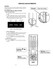
Enter the Service Menu: ∑ Turn off the Service Menu display. vision, reconnect the AC power supply. ITEM NO. Service Adjustments: ∑ Press the Channel L or M key to select the desired service menu item you want to adjust the data. key ... - The Service Menu will increase or decrease the data sequentially. 3. The remote can now be used to turn off the receiver and disconnect the AC power supply. ∑ While pressing the Volume (-) button on the tele- Service Menu Display 2. Channel M L: Select Item Menu: Exit Service Menu - 3 - See page 4 for most of...
Enter the Service Menu: ∑ Turn off the Service Menu display. vision, reconnect the AC power supply. ITEM NO. Service Adjustments: ∑ Press the Channel L or M key to select the desired service menu item you want to adjust the data. key ... - The Service Menu will increase or decrease the data sequentially. 3. The remote can now be used to turn off the receiver and disconnect the AC power supply. ∑ While pressing the Volume (-) button on the tele- Service Menu Display 2. Channel M L: Select Item Menu: Exit Service Menu - 3 - See page 4 for most of...
Service Manual
Page 4
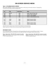
... is initial and can be hexadecimal 08. See page 3 for On-Screen Service Menu access and adjustments. Note 2. If this program code is wrong the TV will not operate properly. -4- Note 1. See 088 above . No. If this model is a multi-purpose type and is used in this program code is wrong... the TV will not operate properly. Title 1A0 MUTE 086 VOL 087 OP1 088 OP2 Initial Data A0h 30h 40h 08h Note Audio mute at Power ON Volume setup inspection Option 1 Data (HDMI) Option 2 Data (Display Panel) 101 1R00...
... is initial and can be hexadecimal 08. See page 3 for On-Screen Service Menu access and adjustments. Note 2. If this program code is wrong the TV will not operate properly. -4- Note 1. See 088 above . No. If this model is a multi-purpose type and is used in this program code is wrong... the TV will not operate properly. Title 1A0 MUTE 086 VOL 087 OP1 088 OP2 Initial Data A0h 30h 40h 08h Note Audio mute at Power ON Volume setup inspection Option 1 Data (HDMI) Option 2 Data (Display Panel) 101 1R00...
Service Manual
Page 5
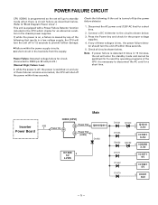
... uncorrected, the CPU will shut off in 1.5 seconds to prevent further damage: • Failure within three seconds. 5. Inverter Power Board Main IC800 (CPU) K8B 1 Power On 18 32 Power Fail Q810/Q811 23 Power Fail (LVDS) D1683 IC1680 2 5V LVDS D1621 D1653 D6053 D1620 5 Q1610 6 3.3V 8 IC1651 6.5V D6052 6 IC6050... the set will go to standby mode when there is circuit failure as described below. (Refer to"Block Diagram Power Lines".) This unit is equipped with a Power Failure Detector function included in the CPU which checks for an abnormal condition in the load side from the supply....
... uncorrected, the CPU will shut off in 1.5 seconds to prevent further damage: • Failure within three seconds. 5. Inverter Power Board Main IC800 (CPU) K8B 1 Power On 18 32 Power Fail Q810/Q811 23 Power Fail (LVDS) D1683 IC1680 2 5V LVDS D1621 D1653 D6053 D1620 5 Q1610 6 3.3V 8 IC1651 6.5V D6052 6 IC6050... the set will go to standby mode when there is circuit failure as described below. (Refer to"Block Diagram Power Lines".) This unit is equipped with a Power Failure Detector function included in the CPU which checks for an abnormal condition in the load side from the supply....
Service Manual
Page 7
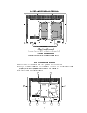
Lift the LCD panel from LCD panel, speakers, and control board. 2. Disconnect the lead wires from the front cabinet. -7- Once you have taken off the Lid back, stand base, power unit and main board remove 9 screws (C:3X14) and 4 screws (D:4X8) to take the back cabinet off LCD panel removal Removal 1. POWER AND MAIN BOARD REMOVAL 1: Main Board Removal Remove 5 screws (3X14) to take the main board off. 2: Power Unit Removal Remove 6 screws (3X14) to take the power unit off . 3.
Lift the LCD panel from LCD panel, speakers, and control board. 2. Disconnect the lead wires from the front cabinet. -7- Once you have taken off the Lid back, stand base, power unit and main board remove 9 screws (C:3X14) and 4 screws (D:4X8) to take the back cabinet off LCD panel removal Removal 1. POWER AND MAIN BOARD REMOVAL 1: Main Board Removal Remove 5 screws (3X14) to take the main board off. 2: Power Unit Removal Remove 6 screws (3X14) to take the power unit off . 3.

Service Manual
Page 38
...will be switched off. No: All 0V (except '5V_STBY' line) Check: arround CPU (IC800), IC (IC801), Crystal (X801), Power Unit Yes (or the voltage to all lines supplied? Power Failure Line CPU (IC800) 32pin Q810, Q811 Diod D1671 D6052/D6053 D1620/D1621 D1662 D1653 D1679 Detected Voltage 9V 3.3V D3....3V 5V 6.5V AUDIO_POW CPU (IC800) 23pin Diod D1683 - 38 - NO POWER TROUBLESHOOTING FLOW CHARTS Is Yes fuse open? Check: Power Unit No Is the...
...will be switched off. No: All 0V (except '5V_STBY' line) Check: arround CPU (IC800), IC (IC801), Crystal (X801), Power Unit Yes (or the voltage to all lines supplied? Power Failure Line CPU (IC800) 32pin Q810, Q811 Diod D1671 D6052/D6053 D1620/D1621 D1662 D1653 D1679 Detected Voltage 9V 3.3V D3....3V 5V 6.5V AUDIO_POW CPU (IC800) 23pin Diod D1683 - 38 - NO POWER TROUBLESHOOTING FLOW CHARTS Is Yes fuse open? Check: Power Unit No Is the...
Service Manual
Page 41
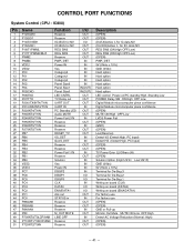
...4 5 6 7 8 9 10 11 12 13 14 15 16 17 18 19 20 21 22 23 24 25 26 27 28 29 30 31 32 33 34 35 36 37 38 39 40 41 42 43 44 45 46 47 48...GND (0Vdc) Hard option Hard option Hard option Hard option Hard option Hard option LED control Power on/PC standby:High, Standby:Low POWER Relay SW ON:High OFF:Low Digital Module microcomputer piece confidence Digital Module microcomputer piece confidence ...OPEN) Low(Reserve) Detect VS (Detect:High, PC Input) Detect HS (Detect:High, PC Input) (OPEN) (OPEN) TV Power Error (L)/Others (H) (OPEN) Solution Option (High:US1H Low:US1F) GND (0Vdc) 5V (5Vdc ± 10%) Terminal ...
...4 5 6 7 8 9 10 11 12 13 14 15 16 17 18 19 20 21 22 23 24 25 26 27 28 29 30 31 32 33 34 35 36 37 38 39 40 41 42 43 44 45 46 47 48...GND (0Vdc) Hard option Hard option Hard option Hard option Hard option Hard option LED control Power on/PC standby:High, Standby:Low POWER Relay SW ON:High OFF:Low Digital Module microcomputer piece confidence Digital Module microcomputer piece confidence ...OPEN) Low(Reserve) Detect VS (Detect:High, PC Input) Detect HS (Detect:High, PC Input) (OPEN) (OPEN) TV Power Error (L)/Others (H) (OPEN) Solution Option (High:US1H Low:US1F) GND (0Vdc) 5V (5Vdc ± 10%) Terminal ...
Service Manual
Page 42
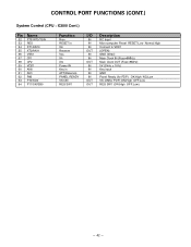
... XT1/AN10 XT2/AN11 VSS1 CF1 CF2 VDD1 AN0 AN1 P82 P10/SO0 P11/SI0/SB0 Function Rcin RESET in Xin Reserve Vss Xti Xto Power IN Key in AFT(Reserve) PANEL READY VS-ON REG SW1 I/O IN IN IN OUT IN IN OUT IN IN IN IN OUT OUT Description...
... XT1/AN10 XT2/AN11 VSS1 CF1 CF2 VDD1 AN0 AN1 P82 P10/SO0 P11/SI0/SB0 Function Rcin RESET in Xin Reserve Vss Xti Xto Power IN Key in AFT(Reserve) PANEL READY VS-ON REG SW1 I/O IN IN IN OUT IN IN OUT IN IN IN IN OUT OUT Description...
Service Manual
Page 43
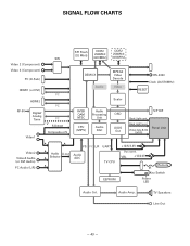
... Back Light level Video data & Clk (LVDS) Panel Unit Video2 Video3 Audio (or DVI Audio) PC Audio (L/R) A A I²S I²C L/R UART A A Audio A-out Selector Audio ADC A TV CPU EEPROM +12/5/3.3V Vcc cont. TV Speakers Line Out - 43 - VBL +12/24V Remote IR Key Switch...
... Back Light level Video data & Clk (LVDS) Panel Unit Video2 Video3 Audio (or DVI Audio) PC Audio (L/R) A A I²S I²C L/R UART A A Audio A-out Selector Audio ADC A TV CPU EEPROM +12/5/3.3V Vcc cont. TV Speakers Line Out - 43 - VBL +12/24V Remote IR Key Switch...

Service Manual
Page 44
VBL +12/24V Remote IR Key Switch Power LED Audio Cnt. TV Speakers Line Out - 44 - SW SPI Flash (32 Mbit) DDR2 256Mbit (400MHz) DDR2 256Mbit (400MHz) Video 2 (Component) Video 3 (Component) PC (D-Sub) DEMUX MPEG2 Video Decode ... Back Light level Video data & Clk (LVDS) Panel Unit Video2 Video3 Audio (or DVI Audio) PC Audio (L/R) A A I²S I²C L/R UART A Audio A-out Audio A Selector ADC TV CPU A EEPROM +12/5/3.3V Vcc cont. Audio Amp.
VBL +12/24V Remote IR Key Switch Power LED Audio Cnt. TV Speakers Line Out - 44 - SW SPI Flash (32 Mbit) DDR2 256Mbit (400MHz) DDR2 256Mbit (400MHz) Video 2 (Component) Video 3 (Component) PC (D-Sub) DEMUX MPEG2 Video Decode ... Back Light level Video data & Clk (LVDS) Panel Unit Video2 Video3 Audio (or DVI Audio) PC Audio (L/R) A A I²S I²C L/R UART A Audio A-out Audio A Selector ADC TV CPU A EEPROM +12/5/3.3V Vcc cont. Audio Amp.
Service Manual
Page 45
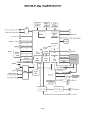
VBL +12/24V Remote IR Key Switch Power LED Audio Cnt. SIGNAL FLOW CHARTS (CONT.) SW SPI Flash (32 Mbit) DDR2 256Mbit (400MHz) DDR2 256Mbit (400MHz) Video 2 (Component) Video 3 (Component) PC (D-Sub) DEMUX ... Light level Video data & Clk (LVDS) Panel Unit A Audio Video2 A Video3 Audio A (or DVI Audio) PC Audio (L/R) A A Audio A-out Selector I²S I²C L/R Audio ADC UART TV CPU EEPROM +12/5/3.3V Vcc cont. TV Speakers Line Out - 45 - Audio Amp.
VBL +12/24V Remote IR Key Switch Power LED Audio Cnt. SIGNAL FLOW CHARTS (CONT.) SW SPI Flash (32 Mbit) DDR2 256Mbit (400MHz) DDR2 256Mbit (400MHz) Video 2 (Component) Video 3 (Component) PC (D-Sub) DEMUX ... Light level Video data & Clk (LVDS) Panel Unit A Audio Video2 A Video3 Audio A (or DVI Audio) PC Audio (L/R) A A Audio A-out Selector I²S I²C L/R Audio ADC UART TV CPU EEPROM +12/5/3.3V Vcc cont. TV Speakers Line Out - 45 - Audio Amp.


