
Service Manual
Page 5
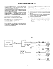
... Lines".) This unit is turned off by any of these failures remains uncorrected, the CPU will shut off the power within three seconds. Inverter Power Board Main IC800 (CPU) K8B 1 Power On 18 32 Power Fail Q810/Q811 23 Power Fail (LVDS) D1683 IC1680 2 5V LVDS D1621 D1653 D6053 D1620 5 Q1610 6 3.3V...
... Lines".) This unit is turned off by any of these failures remains uncorrected, the CPU will shut off the power within three seconds. Inverter Power Board Main IC800 (CPU) K8B 1 Power On 18 32 Power Fail Q810/Q811 23 Power Fail (LVDS) D1683 IC1680 2 5V LVDS D1621 D1653 D6053 D1620 5 Q1610 6 3.3V...
Service Manual
Page 7
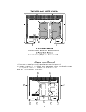
Once you have taken off the Lid back, stand base, power unit and main board remove 9 screws (C:3X14) and 4 screws (D:4X8) to take the back cabinet off LCD panel removal Removal 1. POWER AND MAIN BOARD REMOVAL 1: Main Board Removal Remove 5 screws (3X14) to take the main board off. 2: Power Unit Removal Remove 6 screws (3X14) to take the power unit off . 3. Lift the LCD panel from LCD panel, speakers, and control board. 2. Disconnect the lead wires from the front cabinet. -7-
Once you have taken off the Lid back, stand base, power unit and main board remove 9 screws (C:3X14) and 4 screws (D:4X8) to take the back cabinet off LCD panel removal Removal 1. POWER AND MAIN BOARD REMOVAL 1: Main Board Removal Remove 5 screws (3X14) to take the main board off. 2: Power Unit Removal Remove 6 screws (3X14) to take the power unit off . 3. Lift the LCD panel from LCD panel, speakers, and control board. 2. Disconnect the lead wires from the front cabinet. -7-
Service Manual
Page 26
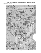
COMPONENT AND TESTPOINT LOCATIONS (CONT.) MAIN BOARD FOIL SIDE 1 1 D6051 1 PB4 D CL14 L1692 K1000 6 L6121 L6602 L6506 L6120 L1724 K801 C IC001A IC001 C002 14 2 B A L1690 L4 L7012 L7011 L7003 CL11 KSP R1677 ... L5971 R5622 C5718 C5719 Q6063 R6064 7 R1711 PB3 R1712 L6516 L7017 CL13 C6115 6 1 SH2 KUSB2 SH4 L7008 L7018 R6117 R6111 R6210 C6203 CL19 D R6200 C CL16 B A - 26 -
COMPONENT AND TESTPOINT LOCATIONS (CONT.) MAIN BOARD FOIL SIDE 1 1 D6051 1 PB4 D CL14 L1692 K1000 6 L6121 L6602 L6506 L6120 L1724 K801 C IC001A IC001 C002 14 2 B A L1690 L4 L7012 L7011 L7003 CL11 KSP R1677 ... L5971 R5622 C5718 C5719 Q6063 R6064 7 R1711 PB3 R1712 L6516 L7017 CL13 C6115 6 1 SH2 KUSB2 SH4 L7008 L7018 R6117 R6111 R6210 C6203 CL19 D R6200 C CL16 B A - 26 -
Service Manual
Page 54
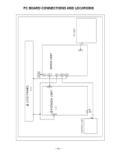
CN903 K8L PC BOARD CONNECTIONS AND LOCATIONS - 54 - LCD PANEL EL901 SPEAKER 2 2 1 1 KSP K8B CN902 POWER UNIT U901 MAIN UNIT K8FRA K5LV CONTROL UNIT 1 5V_STBY 2 GND 3 KEY_IN 4 RC_IN 5 LED_ON GND 6 FROM MAIN UNIT(K8FRA) CN1 K8PC PC UNIT
CN903 K8L PC BOARD CONNECTIONS AND LOCATIONS - 54 - LCD PANEL EL901 SPEAKER 2 2 1 1 KSP K8B CN902 POWER UNIT U901 MAIN UNIT K8FRA K5LV CONTROL UNIT 1 5V_STBY 2 GND 3 KEY_IN 4 RC_IN 5 LED_ON GND 6 FROM MAIN UNIT(K8FRA) CN1 K8PC PC UNIT


