Open Source Guide (ENGLISH)
Page 2
How to Apply These Terms to Your New Libraries If you develop a new library, and you want it to be of the greatest possible use to the public, we recommend making it free software that everyone can do so by permitting redistribution under these terms, attach the following notices to most effectively convey the exclusion of warranty; and each file should have at least the "copyright" line and a pointer to where the full notice is safest to attach them to the start of the ordinary General Public License). 16. You can redistribute and change. To apply these terms (or, alternatively, ...
How to Apply These Terms to Your New Libraries If you develop a new library, and you want it to be of the greatest possible use to the public, we recommend making it free software that everyone can do so by permitting redistribution under these terms, attach the following notices to most effectively convey the exclusion of warranty; and each file should have at least the "copyright" line and a pointer to where the full notice is safest to attach them to the start of the ordinary General Public License). 16. You can redistribute and change. To apply these terms (or, alternatively, ...
User Manual (ENGLISH)
Page 3
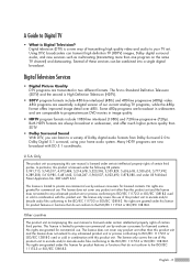
... this product unit and the license does not extend to any unlicensed product unit or process conforming to Dolby Digital 5.1 surround, using your TV set. This license is limited to ISO/IEC 11172-3 or ISO/IEC 13818-3 used or sold in two different formats. The license only covers ...line interlaced (480i) and 480-line progressive (480p) video. 480i programs are granted under certain intellectual property rights of our current analog TV programs, while the 480p format offers improved image detail over 480i. Some 480p programs are broadcast in widescreen and are granted for product ...
... this product unit and the license does not extend to any unlicensed product unit or process conforming to Dolby Digital 5.1 surround, using your TV set. This license is limited to ISO/IEC 11172-3 or ISO/IEC 13818-3 used or sold in two different formats. The license only covers ...line interlaced (480i) and 480-line progressive (480p) video. 480i programs are granted under certain intellectual property rights of our current analog TV programs, while the 480p format offers improved image detail over 480i. Some 480p programs are broadcast in widescreen and are granted for product ...

User Manual (ENGLISH)
Page 4
...of a new digital cable standard. English - 4 They are equipped with a proper digital cable tuner to insert the CableCARD. A digital set-top box which used to be provided by DTLA (Digital Transmission Licensing Administrator). It should be noted that CableCARD is a concerted effort to... www.cablelabs.com. When CableCARD is inserted into the CableCARD slot of a Digital Cable Ready TV. Digital Cable Ready TVs are also designed to download necessary data such as channel information or subscription information from your digital cable service provider....
...of a new digital cable standard. English - 4 They are equipped with a proper digital cable tuner to insert the CableCARD. A digital set-top box which used to be provided by DTLA (Digital Transmission Licensing Administrator). It should be noted that CableCARD is a concerted effort to... www.cablelabs.com. When CableCARD is inserted into the CableCARD slot of a Digital Cable Ready TV. Digital Cable Ready TVs are also designed to download necessary data such as channel information or subscription information from your digital cable service provider....
User Manual (ENGLISH)
Page 5
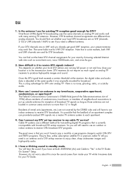
...(channels 14-69) to put up outside antennas for broadcast. So you won't have set top receiver to receive DTV broadcasts. Q&A 1. Over-the-air (OTA) digital TV broadcasting uses the same channels as analog TV receivers to watch OTA DTV and HDTV programs. They're free, unlike subscription satellite...need to use a different method for VHF DTV reception. This is an antenna and a DTV set -top receivers. However, do not require as much signal as analog TV and works well with broadcast DTV set -top receiver to each apartment. 4. You can provide broadcast DTV signals via a master...
...(channels 14-69) to put up outside antennas for broadcast. So you won't have set top receiver to receive DTV broadcasts. Q&A 1. Over-the-air (OTA) digital TV broadcasting uses the same channels as analog TV receivers to watch OTA DTV and HDTV programs. They're free, unlike subscription satellite...need to use a different method for VHF DTV reception. This is an antenna and a DTV set -top receivers. However, do not require as much signal as analog TV and works well with broadcast DTV set -top receiver to each apartment. 4. You can provide broadcast DTV signals via a master...

User Manual (ENGLISH)
Page 6
...Front Panel Indicators 12 Front/Right Side Buttons 13 Side Panel Jacks ...13 Rear Panel Jacks ...14 Remote Control...15 Connections 18 Connecting VHF and UHF Antennas 18 Antennas with 75-ohm Round Leads 18 Connecting Cable TV 19 Cable without a Cable Box 19 Cable with a Cable Box that ...to DVI (Digital Visual Interface 26 Connecting a VCR and DTV Set-Top Box 27 Connecting to HDMI (High Definition Multimedia Interface 27 Connecting a Digital Audio System 28 Connecting to an Analog Amplifier 29 Operation 32 Turning the TV On and Off 32 Dynamic Menus and On-Screen Displays 32 ...
...Front Panel Indicators 12 Front/Right Side Buttons 13 Side Panel Jacks ...13 Rear Panel Jacks ...14 Remote Control...15 Connections 18 Connecting VHF and UHF Antennas 18 Antennas with 75-ohm Round Leads 18 Connecting Cable TV 19 Cable without a Cable Box 19 Cable with a Cable Box that ...to DVI (Digital Visual Interface 26 Connecting a VCR and DTV Set-Top Box 27 Connecting to HDMI (High Definition Multimedia Interface 27 Connecting a Digital Audio System 28 Connecting to an Analog Amplifier 29 Operation 32 Turning the TV On and Off 32 Dynamic Menus and On-Screen Displays 32 ...
User Manual (ENGLISH)
Page 7
... control panel 122 Operating Tips ...124 Recording Tips...126 Tips on stopping recording 126 Troubleshooting (D-Net 127 PC Display 132 Using Your TV as a Computer (PC) Display 132 Adjusting the Picture Quality 135 Changing the Picture Position 136 Adjusting the Picture Quality and Position Automatically... 137 Changing the Picture Size (PC Mode 138 Viewing the Current Resolution 139 Initializing the Picture Settings 140 WISELINK 142 Using the WISELINK Function 142 Using the WISELINK Menu 143 Using the PHOTO (JPEG) List 144 Using the MP3...
... control panel 122 Operating Tips ...124 Recording Tips...126 Tips on stopping recording 126 Troubleshooting (D-Net 127 PC Display 132 Using Your TV as a Computer (PC) Display 132 Adjusting the Picture Quality 135 Changing the Picture Position 136 Adjusting the Picture Quality and Position Automatically... 137 Changing the Picture Size (PC Mode 138 Viewing the Current Resolution 139 Initializing the Picture Settings 140 WISELINK 142 Using the WISELINK Function 142 Using the WISELINK Menu 143 Using the PHOTO (JPEG) List 144 Using the MP3...

User Manual (ENGLISH)
Page 11
If any time you choose • Adjustable picture and sound settings and the ability to memorize your favorite settings • Automatic channel tuning for up to 181 channels • A special filter to reduce or eliminate reception problems • Fine tuning...Registration Card/ Safety Guide Manual/ Quick Guide Manual/ Power Cord (3903-000144) G-LINKTM Cable (MD96-00036A) Cloth-Clean English - 11 List of Features Your TV is missing or broken, call your color preference • Color Weakness Enhancement Feature • Digital Input jack • Digital Audio Output (OPTICAL) jack &#...
If any time you choose • Adjustable picture and sound settings and the ability to memorize your favorite settings • Automatic channel tuning for up to 181 channels • A special filter to reduce or eliminate reception problems • Fine tuning...Registration Card/ Safety Guide Manual/ Quick Guide Manual/ Power Cord (3903-000144) G-LINKTM Cable (MD96-00036A) Cloth-Clean English - 11 List of Features Your TV is missing or broken, call your color preference • Color Weakness Enhancement Feature • Digital Input jack • Digital Audio Output (OPTICAL) jack &#...
User Manual (ENGLISH)
Page 12
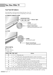
Remote Control Sensor Aim the remote control towards this spot on the TV. Remote Control Sensor Aim the remote control towards this spot on the TV. Lamp cover on the rear of the set is not properly shut. Check if the ventilation hole on the model. A cooling fan inside lamp from overheating. Lamp... depending on the rear of your TV. HL-S7178W POWER Press to turn the TV on in about 30 seconds for the TV to warm up, so normal brightness may not appear immediately. • The TV has a fan to turn the TV on the front panel indicate the status of the set will shut off....
Remote Control Sensor Aim the remote control towards this spot on the TV. Remote Control Sensor Aim the remote control towards this spot on the TV. Lamp cover on the rear of the set is not properly shut. Check if the ventilation hole on the model. A cooling fan inside lamp from overheating. Lamp... depending on the rear of your TV. HL-S7178W POWER Press to turn the TV on in about 30 seconds for the TV to warm up, so normal brightness may not appear immediately. • The TV has a fan to turn the TV on the front panel indicate the status of the set will shut off....

User Manual (ENGLISH)
Page 14
Your New Wide TV Rear Panel Jacks Œ CableCARDTM Insert a CableCARD into the slot. (Refer to page 22) ´... be necessary to make this purpose, which allow you to receive left and right audio from a DVD player or a Set-Top Box. (Refer to pages 24 and 26) Ø PC VIDEO INPUT jack Connect to the video output jack ... a Digital Audio Component. (Refer to page 28) G-LINKTM Connect the IR controller cable to the G-LINKTM terminal on your TV allow for professional linking network and service usage. Ú D-Net (IEEE1394) S400 MPEG Connect to pages 21 and 27) ˆ COMPONENT...
Your New Wide TV Rear Panel Jacks Œ CableCARDTM Insert a CableCARD into the slot. (Refer to page 22) ´... be necessary to make this purpose, which allow you to receive left and right audio from a DVD player or a Set-Top Box. (Refer to pages 24 and 26) Ø PC VIDEO INPUT jack Connect to the video output jack ... a Digital Audio Component. (Refer to page 28) G-LINKTM Connect the IR controller cable to the G-LINKTM terminal on your TV allow for professional linking network and service usage. Ú D-Net (IEEE1394) S400 MPEG Connect to pages 21 and 27) ˆ COMPONENT...
User Manual (ENGLISH)
Page 15
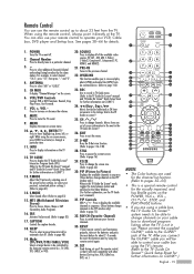
...Refer to select additional channels (digital and analog) being broadcast by the Samsung remote control (i.e., TV, DVD, STB, CABLE, or VCR). 20. SET Used during set of screen information to the G-LINKTM jack of the available video sources (TV, AV1, AV2, AV3, S-Video1, S-Video2, Component1, Component2, ... Press to select "AIR" or "CABLE". 5. INFO Press to the previous channel. 22. P.MODE Adjust the TV picture by selecting one set up of the preset factory settings (or select your favorite channels. 33. PRE-CH Tunes to display information on G-LINKTM.) English - 15 PIP ...
...Refer to select additional channels (digital and analog) being broadcast by the Samsung remote control (i.e., TV, DVD, STB, CABLE, or VCR). 20. SET Used during set of screen information to the G-LINKTM jack of the available video sources (TV, AV1, AV2, AV3, S-Video1, S-Video2, Component1, Component2, ... Press to select "AIR" or "CABLE". 5. INFO Press to the previous channel. 22. P.MODE Adjust the TV picture by selecting one set up of the preset factory settings (or select your favorite channels. 33. PRE-CH Tunes to display information on G-LINKTM.) English - 15 PIP ...

User Manual (ENGLISH)
Page 20
... RF (A/B) switch. 5 Connect the last coaxial cable between the OUT terminal of your Samsung dealer or any electronics store). 1 Find and disconnect the cable that Descrambles Some (But Not All) Channels To complete this connection, set the A/B switch to "B", you will need a two-way splitter, an RF (A/B) ...terminal of the RF (A/B) switch and the ANT 1 IN (CABLE) on the TV. After you've made this connection you set the A/B switch to the Cable box's output channel, which you can buy from your Splitter. Set the A/B switch to the "B" position to view scrambled channels. (When you ...
... RF (A/B) switch. 5 Connect the last coaxial cable between the OUT terminal of your Samsung dealer or any electronics store). 1 Find and disconnect the cable that Descrambles Some (But Not All) Channels To complete this connection, set the A/B switch to "B", you will need a two-way splitter, an RF (A/B) ...terminal of the RF (A/B) switch and the ANT 1 IN (CABLE) on the TV. After you've made this connection you set the A/B switch to the Cable box's output channel, which you can buy from your Splitter. Set the A/B switch to the "B" position to view scrambled channels. (When you ...
User Manual (ENGLISH)
Page 21
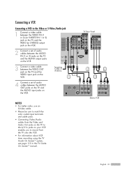
Incoming Cable or Antenna 1 or 4 Connect a set of audio cables between the VIDEO OUT jack on the TV and the VIDEO input jack on the VCR. TV Rear Panel 2 4 3 Stereo VCR English - 21 NOTES • For better video, use an S-Video cable. • Please be sure to match the color coded input ... video cable between the VIDEO IN (1 or 2) (or S-VIDEO IN 1 or 2) jack on the TV and the VIDEO (or S-VIDEO) output jack on the VCR. 2 Connect a set of audio cables between the AUDIO IN (1 or 2) jacks on the TV and the AUDIO output jacks on the VCR. 3 Connect a video cable between the AUDIO...
Incoming Cable or Antenna 1 or 4 Connect a set of audio cables between the VIDEO OUT jack on the TV and the VIDEO input jack on the VCR. TV Rear Panel 2 4 3 Stereo VCR English - 21 NOTES • For better video, use an S-Video cable. • Please be sure to match the color coded input ... video cable between the VIDEO IN (1 or 2) (or S-VIDEO IN 1 or 2) jack on the TV and the VIDEO (or S-VIDEO) output jack on the VCR. 2 Connect a set of audio cables between the AUDIO IN (1 or 2) jacks on the TV and the AUDIO output jacks on the VCR. 3 Connect a video cable between the AUDIO...

User Manual (ENGLISH)
Page 23
If you need to connect a set of two cables. 3 Connect a set of the camcorder. 2 Connect a video or S-Video cable between the AUDIO IN jacks on the TV and the AUDIO output jacks on the camcorder. The audio-video cables shown here are usually found on the side or back ... Camcorder to your Camcorder is stereo, you have a mono Camcorder, connect L(mono) to the Camcorder audio out using only one audio cable. 1 Camcorder Output Jacks TV Rear and right side or Camcorder 2 3 NOTE • Please be sure to view tapes without using a VCR. 1 Locate the A/V output jacks on the camcorder....
If you need to connect a set of two cables. 3 Connect a set of the camcorder. 2 Connect a video or S-Video cable between the AUDIO IN jacks on the TV and the AUDIO output jacks on the camcorder. The audio-video cables shown here are usually found on the side or back ... Camcorder to your Camcorder is stereo, you have a mono Camcorder, connect L(mono) to the Camcorder audio out using only one audio cable. 1 Camcorder Output Jacks TV Rear and right side or Camcorder 2 3 NOTE • Please be sure to view tapes without using a VCR. 1 Locate the A/V output jacks on the camcorder....

User Manual (ENGLISH)
Page 24
...color coded input terminals and cable jacks. English - 24 Incoming Cable or Antenna TV Rear Panel 1 DVD Player Incoming Cable or Antenna 2 1 DVD Player Connecting to Y, PB, PR 1 To enable Component video viewing, connect a set of Component video cables between the COMPONENT (1 or 2) VIDEO (Y, PB, PR)... on the DVD player. 2 Connect a set of audio cables between the HDMI IN 2 (or HDMI 1/DVI IN) jack on the TV and the HDMI OUT jack on the DVD player. Connections Connecting a DVD Player The rear panel jacks on your TV. TV Rear Panel Connecting to HDMI (High Definition Multimedia ...
...color coded input terminals and cable jacks. English - 24 Incoming Cable or Antenna TV Rear Panel 1 DVD Player Incoming Cable or Antenna 2 1 DVD Player Connecting to Y, PB, PR 1 To enable Component video viewing, connect a set of Component video cables between the COMPONENT (1 or 2) VIDEO (Y, PB, PR)... on the DVD player. 2 Connect a set of audio cables between the HDMI IN 2 (or HDMI 1/DVI IN) jack on the TV and the HDMI OUT jack on the DVD player. Connections Connecting a DVD Player The rear panel jacks on your TV. TV Rear Panel Connecting to HDMI (High Definition Multimedia ...

User Manual (ENGLISH)
Page 25
TV Rear Panel Incoming Cable or Antenna 1 2 DVD Player English - 25 Connecting to match the color coded input terminals and cable jacks. NOTES • Component Video separates the video into Y(Luminance (Brightness)), Pb (Blue) and Pr (Red) for enhanced video quality. • Please be sure to Audio and Video Jacks 1 Connect a video cable between the VIDEO IN (1 or 2) jack on the TV and the VIDEO OUT jack on the DVD player. 2 Connect a set of audio cables between the AUDIO IN (1 or 2) jacks on the TV and the AUDIO OUT jacks on the DVD player.
TV Rear Panel Incoming Cable or Antenna 1 2 DVD Player English - 25 Connecting to match the color coded input terminals and cable jacks. NOTES • Component Video separates the video into Y(Luminance (Brightness)), Pb (Blue) and Pr (Red) for enhanced video quality. • Please be sure to Audio and Video Jacks 1 Connect a video cable between the VIDEO IN (1 or 2) jack on the TV and the VIDEO OUT jack on the DVD player. 2 Connect a set of audio cables between the AUDIO IN (1 or 2) jacks on the TV and the AUDIO OUT jacks on the DVD player.

User Manual (ENGLISH)
Page 26
Incoming Cable or Antenna English - 26 DTV Set-Top Box TV Rear Panel 2 1 DTV Set-Top Box TV Rear Panel 1 2 NOTES • Please be unable to select it in the TV menu's source list. • The HDMI 1/DVI IN jack is on, or you will be sure to match the color coded input terminals and cable... HDMI/DVI cable between the HDMI 1/DVI IN jack on the TV and the DVI OUT jack on the Set-Top Box. 2 Connect a set of audio cables between the COMPONENT (1 or 2) AUDIO (L, R) IN jacks on the TV and the AUDIO OUT jacks on the Set-Top Box. NOTES • Requires a Cable Converter. • To...
Incoming Cable or Antenna English - 26 DTV Set-Top Box TV Rear Panel 2 1 DTV Set-Top Box TV Rear Panel 1 2 NOTES • Please be unable to select it in the TV menu's source list. • The HDMI 1/DVI IN jack is on, or you will be sure to match the color coded input terminals and cable... HDMI/DVI cable between the HDMI 1/DVI IN jack on the TV and the DVI OUT jack on the Set-Top Box. 2 Connect a set of audio cables between the COMPONENT (1 or 2) AUDIO (L, R) IN jacks on the TV and the AUDIO OUT jacks on the Set-Top Box. NOTES • Requires a Cable Converter. • To...

User Manual (ENGLISH)
Page 27
...) 1 Connect an HDMI cable between the splitter and the ANT IN on the Set-Top Box. TV Rear Panel or 1 Stereo VCR Stereo VCR 4 NOTE • Please be sure to connect between the splitter and the ANT 1 IN (CABLE) on the TV and between the HDMI IN 2 (or HDMI 1/DVI IN) jack on the... TV and the HDMI OUT jack on the Set-Top Box. Incoming Cable or Antenna 1 DTV Set-Top Box English - 27 Incoming Cable or Antenna TV Rear Panel 2 Connect the Video/Audio cables between the...
...) 1 Connect an HDMI cable between the splitter and the ANT IN on the Set-Top Box. TV Rear Panel or 1 Stereo VCR Stereo VCR 4 NOTE • Please be sure to connect between the splitter and the ANT 1 IN (CABLE) on the TV and between the HDMI IN 2 (or HDMI 1/DVI IN) jack on the... TV and the HDMI OUT jack on the Set-Top Box. Incoming Cable or Antenna 1 DTV Set-Top Box English - 27 Incoming Cable or Antenna TV Rear Panel 2 Connect the Video/Audio cables between the...

User Manual (ENGLISH)
Page 28
... of an audio system is connected to the Digital Audio 1 Out (Optical) terminal: Decrease the gain (volume) of digital audio systems on the TV. TV Rear Panel NOTES • OPTICAL: converts the electric signal into an optical light signal, and transmits it through glass fibers. • When a Digital ...Optical, L/R Out) Internal Mute Off Internal Mute On Active Active Active Active Video Output Active Inactive When "Internal mute" is set to the "DIGITAL AUDIO OUT(OPTICAL)" jack on the market today. Connections Connecting a Digital Audio System There are many types of the...
... of an audio system is connected to the Digital Audio 1 Out (Optical) terminal: Decrease the gain (volume) of digital audio systems on the TV. TV Rear Panel NOTES • OPTICAL: converts the electric signal into an optical light signal, and transmits it through glass fibers. • When a Digital ...Optical, L/R Out) Internal Mute Off Internal Mute On Active Active Active Active Video Output Active Inactive When "Internal mute" is set to the "DIGITAL AUDIO OUT(OPTICAL)" jack on the market today. Connections Connecting a Digital Audio System There are many types of the...

User Manual (ENGLISH)
Page 29
.... • If using the HDMI/DVI, PC, or Component input on the TV, the audio output signal is available only when the TV's Internal Mute is set to on. (Refer to page 86) • Please be used for external speakers. TV Rear Panel 1 Amplifier English - 29 You must hook them up to match the color...
.... • If using the HDMI/DVI, PC, or Component input on the TV, the audio output signal is available only when the TV's Internal Mute is set to on. (Refer to page 86) • Please be used for external speakers. TV Rear Panel 1 Amplifier English - 29 You must hook them up to match the color...

User Manual (ENGLISH)
Page 32
...the selected source. The information displayed varies according to select an item you to select menu items and make some adjustments using the TV's front/right side panel buttons. Picture Enter Viewing the Display Press the INFO button on -screen menu system by pressing the ... menu. Selects the input options. Access the on the Cable remote control. 3 The TV displays the current channel, the status of your remote control to control the settings of certain picture, sound settings and the current time. Viewing the Menus 1 Press the MENU button. No Time Information...
...the selected source. The information displayed varies according to select an item you to select menu items and make some adjustments using the TV's front/right side panel buttons. Picture Enter Viewing the Display Press the INFO button on -screen menu system by pressing the ... menu. Selects the input options. Access the on the Cable remote control. 3 The TV displays the current channel, the status of your remote control to control the settings of certain picture, sound settings and the current time. Viewing the Menus 1 Press the MENU button. No Time Information...


