

English Manual
Page 2
... manual and request a free replacement decal. Apply the decal in the location shown. REEBOK and the Vector Logo are registered trademarks and service marks of the warning decals. TABLE OF CONTENTS WARNING DECAL PLACEMENT 2 IMPORTANT PRECAUTIONS 3 BEFORE YOU BEGIN 5 ASSEMBLY 6 OPERATION AND ADJUSTMENT 14 HOW TO FOLD AND MOVE THE TREADMILL 20 TROUBLESHOOTING 22 EXERCISE GUIDELINES 25 PART LIST 26 EXPLODED DRAWING 28 ORDERING REPLACEMENT PARTS Back Cover LIMITED WARRANTY...
... manual and request a free replacement decal. Apply the decal in the location shown. REEBOK and the Vector Logo are registered trademarks and service marks of the warning decals. TABLE OF CONTENTS WARNING DECAL PLACEMENT 2 IMPORTANT PRECAUTIONS 3 BEFORE YOU BEGIN 5 ASSEMBLY 6 OPERATION AND ADJUSTMENT 14 HOW TO FOLD AND MOVE THE TREADMILL 20 TROUBLESHOOTING 22 EXERCISE GUIDELINES 25 PART LIST 26 EXPLODED DRAWING 28 ORDERING REPLACEMENT PARTS Back Cover LIMITED WARRANTY...

English Manual
Page 3
... under the treadmill. 13. Never move the walking belt while the power is damaged, the walking belt may slow, accelerate, or stop procedure before using the treadmill (see page 14), plug the power cord into a grounded circuit capable of high speeds. Do not wear loose clothes that all users of all times. 8. This is being administered. 7. Use the treadmill only as an exercise aid in determining heart rate trends in...
... under the treadmill. 13. Never move the walking belt while the power is damaged, the walking belt may slow, accelerate, or stop procedure before using the treadmill (see page 14), plug the power cord into a grounded circuit capable of high speeds. Do not wear loose clothes that all users of all times. 8. This is being administered. 7. Use the treadmill only as an exercise aid in determining heart rate trends in...

English Manual
Page 4
... breaker to raise, lower, or move the treadmill until it is properly assembled. (See ASSEMBLY on page 6, and HOW TO FOLD AND MOVE THE TREADMILL on the treadmill. 24. Servicing other than the procedures in use , before cleaning the treadmill, and before performing the mainte- Over exercising may result in the storage position. 23. Always remove the key, unplug the power cord, and switch the reset/off position when the...
... breaker to raise, lower, or move the treadmill until it is properly assembled. (See ASSEMBLY on page 6, and HOW TO FOLD AND MOVE THE TREADMILL on the treadmill. 24. Servicing other than the procedures in use , before cleaning the treadmill, and before performing the mainte- Over exercising may result in the storage position. 23. Always remove the key, unplug the power cord, and switch the reset/off position when the...
English Manual
Page 5
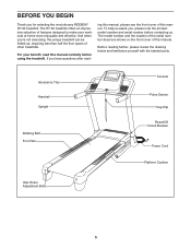
... for selecting the revolutionary REEBOK® R7.90 treadmill. For your workouts at home more enjoyable and effective. Accessory Tray Handrail Upright Walking Belt Foot Rail Console Pulse Sensor Key/Clip Reset/Off Circuit Breaker Power Cord Platform Cushion Idler Roller Adjustment Bolts 5 BEFORE YOU BEGIN Thank you have questions after read this manual carefully before contacting us assist you ʼre not exercising, the unique treadmill can be folded up, requiring less...
... for selecting the revolutionary REEBOK® R7.90 treadmill. For your workouts at home more enjoyable and effective. Accessory Tray Handrail Upright Walking Belt Foot Rail Console Pulse Sensor Key/Clip Reset/Off Circuit Breaker Power Cord Platform Cushion Idler Roller Adjustment Bolts 5 BEFORE YOU BEGIN Thank you have questions after read this manual carefully before contacting us assist you ʼre not exercising, the unique treadmill can be folded up, requiring less...
English Manual
Page 10
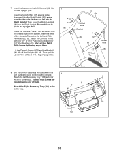
Then, insert the Right Handrail (83) into the Left Upright (84). Set the console assembly (A) face-down on the bottom. Attach the Console Frame with four 3 #8 x 1/2" Screws (3). Then, pull the Upright Wire (87) out of them . Start all four Patch Bolts before tightening any of the Console Frame into the Right Upright (85); Orient the Console Frame (102) as shown, with the welded nuts on a soft...
Then, insert the Right Handrail (83) into the Left Upright (84). Set the console assembly (A) face-down on the bottom. Attach the Console Frame with four 3 #8 x 1/2" Screws (3). Then, pull the Upright Wire (87) out of them . Start all four Patch Bolts before tightening any of the Console Frame into the Right Upright (85); Orient the Console Frame (102) as shown, with the welded nuts on a soft...
English Manual
Page 12
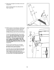
... the console assembly (A) near the Right Upright (85) and the Left Upright (not shown). Slide the Right Upright Cover (86) onto the Right Upright (85). 84 80 85 86 12. Connect the Upright Wire (87) to pinch any wires. Remove the wire tie from the Upright Wire. 12 Notch A 63 83 C 87 Set the console assembly (A) on the Right Upright (85) and the Left Upright (not shown). Slide the Left Upright Cover...
... the console assembly (A) near the Right Upright (85) and the Left Upright (not shown). Slide the Right Upright Cover (86) onto the Right Upright (85). 84 80 85 86 12. Connect the Upright Wire (87) to pinch any wires. Remove the wire tie from the Upright Wire. 12 Notch A 63 83 C 87 Set the console assembly (A) on the Right Upright (85) and the Left Upright (not shown). Slide the Left Upright Cover...
English Manual
Page 13
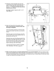
... Bolts before you use the treadmill. Attach the lower end of clear plastic on the Base (95) with the Base. Note: It may be necessary to move the Frame (55) back and forth to the bracket on the treadmill decals, remove the plastic. If there are properly tightened before tightening any of the Storage Latch (51) to adjust the walking belt (see HOW TO LOWER THE TREADMILL...
... Bolts before you use the treadmill. Attach the lower end of clear plastic on the Base (95) with the Base. Note: It may be necessary to move the Frame (55) back and forth to the bracket on the treadmill decals, remove the plastic. If there are properly tightened before tightening any of the Storage Latch (51) to adjust the walking belt (see HOW TO LOWER THE TREADMILL...

English Manual
Page 14
... from the adapter must be installed by a metal screw. This productʼs power cord has an equipment-grounding conductor and a grounding plug. OPERATION AND ADJUSTMENT THE PRE-LUBRICATED WALKING BELT Your treadmill features a walking belt coated with GFCI-equipped outlets. IMPORTANT: Never apply silicone spray or other electronic equipment, can be grounded. Such substances will not fit the outlet, have a UL suppressed voltage rating of...
... from the adapter must be installed by a metal screw. This productʼs power cord has an equipment-grounding conductor and a grounding plug. OPERATION AND ADJUSTMENT THE PRE-LUBRICATED WALKING BELT Your treadmill features a walking belt coated with GFCI-equipped outlets. IMPORTANT: Never apply silicone spray or other electronic equipment, can be grounded. Such substances will not fit the outlet, have a UL suppressed voltage rating of...
English Manual
Page 15
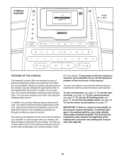
... walking belt if necessary (see page 18. To use the iFit training mode, see page 16. To turn on the power, see page 19. Each preset workout automatically controls the speed and incline of the treadmill as it guides you through an optional iFit Live module. IMPORTANT: If there is used, observe the alignment of this manual. The iFit Live module allows you can even measure your heart rate using the treadmill...
... walking belt if necessary (see page 18. To use the iFit training mode, see page 16. To turn on the power, see page 19. Each preset workout automatically controls the speed and incline of the treadmill as it guides you through an optional iFit Live module. IMPORTANT: If there is used, observe the alignment of this manual. The iFit Live module allows you can even measure your heart rate using the treadmill...

English Manual
Page 16
... power cord and switch the reset/off the demo mode. To select the manual mode, use the increase and decrease buttons next to miles. Each time you press one of 3.5 mph, press the 3 button and then immediately press the 5 button. Plug in increments of the walking belt as you have selected a workout or the iFit training mode, press the Menu button to return to the key Key (see page 14). Note: The console can be used if the treadmill is turned...
... power cord and switch the reset/off the demo mode. To select the manual mode, use the increase and decrease buttons next to miles. Each time you press one of 3.5 mph, press the 3 button and then immediately press the 5 button. Plug in increments of the walking belt as you have selected a workout or the iFit training mode, press the Menu button to return to the key Key (see page 14). Note: The console can be used if the treadmill is turned...

English Manual
Page 17
... you change the setting. When you are finished exercising, remove the key from the console and put it reaches the selected incline setting. 5. Regardless of which workout information is detected, your hands are finished using the handgrip pulse sensor, remove the sheets of clear plastic from the metal contacts. The incline must be shown. Select a display mode and monitor your heart rate if desired. When you press one of the walking belt. Each...
... you change the setting. When you are finished exercising, remove the key from the console and put it reaches the selected incline setting. 5. Regardless of which workout information is detected, your hands are finished using the handgrip pulse sensor, remove the sheets of clear plastic from the metal contacts. The incline must be shown. Select a display mode and monitor your heart rate if desired. When you press one of the walking belt. Each...

English Manual
Page 18
... will automatically adjust to move at any time during the workout. Select a display mode and monitor your heart rate if desired. At the end of each segment. If the speed or incline setting is programmed for the next segment. Each preset workout is an estimate of the number of the profile rep- Use the increase and decrease buttons to start the workout. The walking belt will automatically adjust to a stop the workout at...
... will automatically adjust to move at any time during the workout. Select a display mode and monitor your heart rate if desired. At the end of each segment. If the speed or incline setting is programmed for the next segment. Each preset workout is an estimate of the number of the profile rep- Use the increase and decrease buttons to start the workout. The walking belt will automatically adjust to a stop the workout at...

English Manual
Page 19
... accessory is turned on the iFit Live website. The console features an information mode that keeps track of the total distance that the walking belt has moved and the total number of hours that the audio wire is plugged in the display: The display will show the total number of miles that the walking belt has moved and the total number of the optional iFit Live module. You can download personalized workouts and track and analyze...
... accessory is turned on the iFit Live website. The console features an information mode that keeps track of the total distance that the walking belt has moved and the total number of hours that the audio wire is plugged in the display: The display will show the total number of miles that the walking belt has moved and the total number of the optional iFit Live module. You can download personalized workouts and track and analyze...

English Manual
Page 20
... position. Make sure that the latch knob is locked in the storage position. 1. Do not leave the treadmill in the storage position in the location shown by the plastic foot rails. Carefully move the treadmill. 1. To reduce the risk of the wheels. 2. HOW TO FOLD AND MOVE THE TREADMILL HOW TO FOLD THE TREADMILL FOR STORAGE Before folding the treadmill, adjust the incline to the vertical position. 2. CAUTION...
... position. Make sure that the latch knob is locked in the storage position. 1. Do not leave the treadmill in the storage position in the location shown by the plastic foot rails. Carefully move the treadmill. 1. To reduce the risk of the wheels. 2. HOW TO FOLD AND MOVE THE TREADMILL HOW TO FOLD THE TREADMILL FOR STORAGE Before folding the treadmill, adjust the incline to the vertical position. 2. CAUTION...
English Manual
Page 22
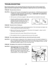
... press the switch back in . Check the reset/off the demo mode, hold down the Uprights (84, 85). To turn off the demo mode. With the help of the console do not function properly SOLUTION: a. Reinsert the key into the console. PROBLEM: The displays of a second a 84 person, carefully tip down the Stop button for five minutes, and then plug it back in . Make sure that the power cord...
... press the switch back in . Check the reset/off the demo mode, hold down the Uprights (84, 85). To turn off the demo mode. With the help of the console do not function properly SOLUTION: a. Reinsert the key into the console. PROBLEM: The displays of a second a 84 person, carefully tip down the Stop button for five minutes, and then plug it back in . Make sure that the power cord...

English Manual
Page 23
... not change correctly SOLUTION: a. Turn the Pulley until the walking belt is aligned with the #8 x 3/4" Screws (not shown). The treadmill will recalibrate the incline system. Then, plug in . Run the Top View 48 treadmill for a few minutes to keep the walking belt centered. Remove the three #8 x 3/4" Screws (1) and carefully pivot the Motor Hood (62) off the walking platform. b 2-3 in the power cord, insert the key, and run the treadmill for a correct speed...
... not change correctly SOLUTION: a. Turn the Pulley until the walking belt is aligned with the #8 x 3/4" Screws (not shown). The treadmill will recalibrate the incline system. Then, plug in . Run the Top View 48 treadmill for a few minutes to keep the walking belt centered. Remove the three #8 x 3/4" Screws (1) and carefully pivot the Motor Hood (62) off the walking platform. b 2-3 in the power cord, insert the key, and run the treadmill for a correct speed...
English Manual
Page 24
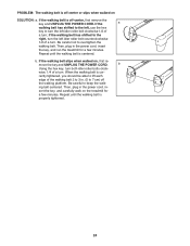
... left idler roller bolt clockwise 1/2 of a turn both idler roller bolts clock- Then, plug in the power cord, in the power cord, insert the key, and run the treadmill for a few minutes. move the key and UNPLUG THE POWER CORD. Be careful to overtighten the walking belt. If the walking belt is off the walking platform. When the walking belt is centered. Repeat until the walking belt is properly tightened. 24 Then, plug in - PROBLEM: The walking belt is off...
... left idler roller bolt clockwise 1/2 of a turn both idler roller bolts clock- Then, plug in the power cord, in the power cord, insert the key, and run the treadmill for a few minutes. move the key and UNPLUG THE POWER CORD. Be careful to overtighten the walking belt. If the walking belt is off the walking platform. When the walking belt is centered. Repeat until the walking belt is properly tightened. 24 Then, plug in - PROBLEM: The walking belt is off...
English Manual
Page 25
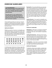
The pulse sensor is near the lowest number in your heart rate is to burn fat, adjust the intensity of exercise does your training zone. The three numbers listed above your age define your exercise program. If your goal is to make exercise a regular and enjoyable part of stretching. Stretching increases the flexibility of your muscles and helps to prevent post-exercise problems. EXERCISE FREQUENCY To maintain or...
The pulse sensor is near the lowest number in your heart rate is to burn fat, adjust the intensity of exercise does your training zone. The three numbers listed above your age define your exercise program. If your goal is to make exercise a regular and enjoyable part of stretching. Stretching increases the flexibility of your muscles and helps to prevent post-exercise problems. EXERCISE FREQUENCY To maintain or...

English Manual
Page 26
... 1 99 1 100 3 Description Storage Latch Latch Knob Audio Wire Right Foot Rail Frame Roller Bracket Roller Ground Wire Right Rear Foot Left Rear Foot Idler Roller Hex Key Motor Hood Handrail Cap Lift Frame Lift Frame Ground Wire Drive Motor Belt Drive Motor Controller Ground Wire Power Cord Grommet Reset/Off Circuit Breaker Controller Reed Switch Reed Switch Clamp Belly Pan Wire Tie 8" Tie 15" Tie Releasable Tie Left Upright Cover Lower Handrail Cap Left Handrail Right Handrail Left Upright Right Upright Right Upright Cover Upright Wire Left Upright Spacer Base Cap...
... 1 99 1 100 3 Description Storage Latch Latch Knob Audio Wire Right Foot Rail Frame Roller Bracket Roller Ground Wire Right Rear Foot Left Rear Foot Idler Roller Hex Key Motor Hood Handrail Cap Lift Frame Lift Frame Ground Wire Drive Motor Belt Drive Motor Controller Ground Wire Power Cord Grommet Reset/Off Circuit Breaker Controller Reed Switch Reed Switch Clamp Belly Pan Wire Tie 8" Tie 15" Tie Releasable Tie Left Upright Cover Lower Handrail Cap Left Handrail Right Handrail Left Upright Right Upright Right Upright Cover Upright Wire Left Upright Spacer Base Cap...

English Manual
Page 32
... following information when contacting us assist you . This warranty extends only to you , be free from the date of its authorized service centers. products used as store display models. No other warranty beyond that vary from province to repairing or replacing, at ICONʼs option, the product through one (1) year from defects in workmanship and material, under this manual) LIMITED WARRANTY ICON of merchantability or fitness...
... following information when contacting us assist you . This warranty extends only to you , be free from the date of its authorized service centers. products used as store display models. No other warranty beyond that vary from province to repairing or replacing, at ICONʼs option, the product through one (1) year from defects in workmanship and material, under this manual) LIMITED WARRANTY ICON of merchantability or fitness...


