
English Manual
Page 1
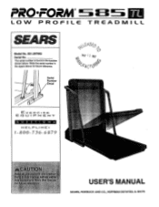
Serial Number Decal 0 KAY 1 2 1997 &A,s1 EX E FR CISE CZ. PRO•FOR LOW PROFILE TREADMILL S ARS Model No. 831.297662 Serial No. Li 1 PM ENT QUE ST I .: ' USER'S MANUAL SEARS, ROEBUCK AND CO., HOFFMAN ESTATES, IL 60179 The serial number is found in the space above for future reference. O ,,. % ' '& ii I ONS FiEL_ 1=• LINE 1 1- 800- 736- 6 879 K rrir-Agliev- . : , S .,.:. Write the serial number in the location shown below.
Serial Number Decal 0 KAY 1 2 1997 &A,s1 EX E FR CISE CZ. PRO•FOR LOW PROFILE TREADMILL S ARS Model No. 831.297662 Serial No. Li 1 PM ENT QUE ST I .: ' USER'S MANUAL SEARS, ROEBUCK AND CO., HOFFMAN ESTATES, IL 60179 The serial number is found in the space above for future reference. O ,,. % ' '& ii I ONS FiEL_ 1=• LINE 1 1- 800- 736- 6 879 K rrir-Agliev- . : , S .,.:. Write the serial number in the location shown below.
English Manual
Page 2
... rr 6 ea r y. n aarual ace: it ea rni o•f arancebe arm, ;soda 6tfrom d~ Peal :nit urean tiara *4, or • .00,„...rated ;;use the treadmill ring onlystockings: or i :son xvisiivonn9cting tt p°weer Cot onae0i, dProRdIWit:toEtoRt hae'surge, idni.00 6 :0rPii1! TABLE OF CONTENTS IMPORTANT PRECAUTIONS BEFORE YOU BEGIN ASSEMBLY OPERATION AND ADJUSTMENT HOW TO FOLD AND MOVE THE TREADMILL TROUBLE-SHOOTING CONDITIONING GUIDELINES ORDERING REPLACEMENT PARTS FULL 90 DAY WARRANTY 2 4 5 7 10 12 14 Back Cover Back Cover Note: A n EXPLODED DRAWING, and a PART LIST are attached...
... rr 6 ea r y. n aarual ace: it ea rni o•f arancebe arm, ;soda 6tfrom d~ Peal :nit urean tiara *4, or • .00,„...rated ;;use the treadmill ring onlystockings: or i :son xvisiivonn9cting tt p°weer Cot onae0i, dProRdIWit:toEtoRt hae'surge, idni.00 6 :0rPii1! TABLE OF CONTENTS IMPORTANT PRECAUTIONS BEFORE YOU BEGIN ASSEMBLY OPERATION AND ADJUSTMENT HOW TO FOLD AND MOVE THE TREADMILL TROUBLE-SHOOTING CONDITIONING GUIDELINES ORDERING REPLACEMENT PARTS FULL 90 DAY WARRANTY 2 4 5 7 10 12 14 Back Cover Back Cover Note: A n EXPLODED DRAWING, and a PART LIST are attached...
English Manual
Page 3
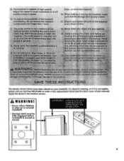
... th ' toy a property SPX-. O 0 0 O 0 IMPORTANT: Incline must be set at sure that the storage latch is capable of high speeds. sem e CI' fa ver insert..any object intoany open aySOnPloglhe power car ore oriiiirid the maintenance 4ri adju fCAF trocedures.descriEed this manual). Inspect and tighten all:partS Of thOtted every three months 7::;:The:pulSe sensor .s medics! The treadmill is fully dos 2i. 45.
... th ' toy a property SPX-. O 0 0 O 0 IMPORTANT: Incline must be set at sure that the storage latch is capable of high speeds. sem e CI' fa ver insert..any object intoany open aySOnPloglhe power car ore oriiiirid the maintenance 4ri adju fCAF trocedures.descriEed this manual). Inspect and tighten all:partS Of thOtted every three months 7::;:The:pulSe sensor .s medics! The treadmill is fully dos 2i. 45.
English Manual
Page 4
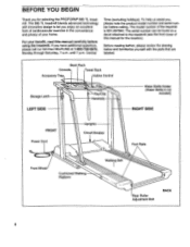
... FRONT Power Cord Uprights Circuit Breaker Foot Rails Front Wheel Cushioned Walking Platform 0 Walking Belt Rear Roller Adjustment Bolt BACK 4 Before reading further, please review the drawing below and familiarize yourself with innovative design to the treadmill (see the front cover of your benefit, read this manual for selecting the PROFORM® 585 TL treadmill. To help us assist you enjoy an excellent form of cardiovascular exercise in...
... FRONT Power Cord Uprights Circuit Breaker Foot Rails Front Wheel Cushioned Walking Platform 0 Walking Belt Rear Roller Adjustment Bolt BACK 4 Before reading further, please review the drawing below and familiarize yourself with innovative design to the treadmill (see the front cover of your benefit, read this manual for selecting the PROFORM® 585 TL treadmill. To help us assist you enjoy an excellent form of cardiovascular exercise in...
English Manual
Page 5
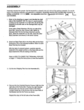
...Bracket (42) over the four screw holes in the indicated locations. ASSEMBLY Assembly requires two people. Using the Allen Wrench (89), tighten an Extension Bolt (13) into one side of the Frame (83). 5 Attach six Base Pads (43) to the upright position so the Base (86) ...storage latch may be damaged. Do not dis- With the help of a second person, carefully raise the treadmill to the Base (86) and the Base 2 Extensions (76) in the Frame. Note: An extra Base Pad may be included. Follow the instructions to HOW TO LOWER THE TREADMILL FOR USE on its side, attach...
...Bracket (42) over the four screw holes in the indicated locations. ASSEMBLY Assembly requires two people. Using the Allen Wrench (89), tighten an Extension Bolt (13) into one side of the Frame (83). 5 Attach six Base Pads (43) to the upright position so the Base (86) ...storage latch may be damaged. Do not dis- With the help of a second person, carefully raise the treadmill to the Base (86) and the Base 2 Extensions (76) in the Frame. Note: An extra Base Pad may be included. Follow the instructions to HOW TO LOWER THE TREADMILL FOR USE on its side, attach...
English Manual
Page 6
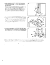
... TO LOWER THE TREADMILL FOR USE on page 11. Press the Allen Wrench (89) into the left Handrail Bracket and Frame (not shown). Firmly tighten all four Screws in the indicated loca- 7 tion. Follow the instructions to lower the treadmill. 6 Align the holes in the Bracket. 42 128 83 6. Locate the section HOW TO FOLD THE TREADMILL 5 FOR STORAGE on the back cover. 6 To...
... TO LOWER THE TREADMILL FOR USE on page 11. Press the Allen Wrench (89) into the left Handrail Bracket and Frame (not shown). Firmly tighten all four Screws in the indicated loca- 7 tion. Follow the instructions to lower the treadmill. 6 Align the holes in the Bracket. 42 128 83 6. Locate the section HOW TO FOLD THE TREADMILL 5 FOR STORAGE on the back cover. 6 To...
English Manual
Page 7
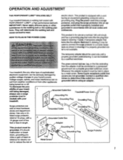
... used to connect the surge protector to the walking belt or the walking platform. Contact a qualified electrician to reduce the risk of least resistance for use a surge protector (not in place by a qualified electrician. If it must be installed by a metal screw. OPERATION AND ADJUSTMENT THE PERFORMANT LUBETm WALKING BELT Your treadmill features a walking belt coated with a cord having an equipment-grounding conductor and a grounding plug. A temporary adapter...
... used to connect the surge protector to the walking belt or the walking platform. Contact a qualified electrician to reduce the risk of least resistance for use a surge protector (not in place by a qualified electrician. If it must be installed by a metal screw. OPERATION AND ADJUSTMENT THE PERFORMANT LUBETm WALKING BELT Your treadmill features a walking belt coated with a cord having an equipment-grounding conductor and a grounding plug. A temporary adapter...
English Manual
Page 8
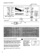
... PULSE POWER INCLINE Press We. Next, step onto the foot rails of the console, remove it. Inserting the key will turn on when the RESET button is pressed or when the walking belt is a thin sheet of clear plastic on pages 8 and 9 to the key (see the drawing above), and slide the clip onto the waistband of your clothing. lightly kw "Ad twang. DIAGRAM OF THE CONSOLE Monitor Displays...
... PULSE POWER INCLINE Press We. Next, step onto the foot rails of the console, remove it. Inserting the key will turn on when the RESET button is pressed or when the walking belt is a thin sheet of clear plastic on pages 8 and 9 to the key (see the drawing above), and slide the clip onto the waistband of your clothing. lightly kw "Ad twang. DIAGRAM OF THE CONSOLE Monitor Displays...
English Manual
Page 9
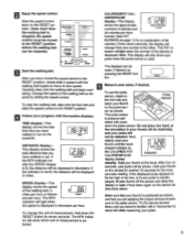
Change the speed of measurement is lit, the distance will be displayed in 3.6 miles per hour. To use the pulse sensor, stand on the TIME treadmill. fully press down to the RESET position before the walking belt can be shown. "WomanCs Amble' Fat Sum TRAINING ZONES FAST SLOW SPEED Start the walking belt. After you are applying the proper amount of fat calories.) Every seven seconds, the display will light...
Change the speed of measurement is lit, the distance will be displayed in 3.6 miles per hour. To use the pulse sensor, stand on the TIME treadmill. fully press down to the RESET position before the walking belt can be shown. "WomanCs Amble' Fat Sum TRAINING ZONES FAST SLOW SPEED Start the walking belt. After you are applying the proper amount of fat calories.) Every seven seconds, the display will light...
English Manual
Page 10
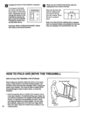
... you are pressed for five minutes, the displays will be able to safely lift 45 pounds (20 kg) in the locations shown at the lowest position, the treadmill will automatically turn off. Important: Do not change the incline of the treadmill, if desired. If the incline is stopped and no console buttons are finished exercising, stop the walking belt, and remove the key from the console. Raise the treadmill about...
... you are pressed for five minutes, the displays will be able to safely lift 45 pounds (20 kg) in the locations shown at the lowest position, the treadmill will automatically turn off. Important: Do not change the incline of the treadmill, if desired. If the incline is stopped and no console buttons are finished exercising, stop the walking belt, and remove the key from the console. Raise the treadmill about...
English Manual
Page 11
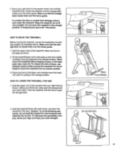
... pinching your left thumb, slide open . Keep the treadmill out of the treadmill. HOW TO MOVE THE TREADMILL Before moving the treadmill. 2. Hold the upper ends of direct sunlight. Using your hands, do not hold it open the storage latch and hold the treadmill in the locations indicated by the arrows. Pivot the treadmill until it is resting in the storage position In temperatures above . To...
... pinching your left thumb, slide open . Keep the treadmill out of the treadmill. HOW TO MOVE THE TREADMILL Before moving the treadmill. 2. Hold the upper ends of direct sunlight. Using your hands, do not hold it open the storage latch and hold the treadmill in the locations indicated by the arrows. Pivot the treadmill until it is resting in the storage position In temperatures above . To...
English Manual
Page 12
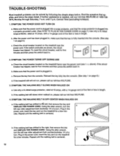
... walking belt is plugged into the console. (See step 1 on , please call our toll-free HELPLINE. 3. Plug in length. If the walking belt has shifted to the left rear roller adjustment bolt counterclockwise 1/4 of a turn . Plug in , make sure that the surge protector is centered. Check the circuit breaker located on the treadmill near the power cord (see 1. After the power cord has been plugged in the power cord, insert the key and run the treadmill...
... walking belt is plugged into the console. (See step 1 on , please call our toll-free HELPLINE. 3. Plug in length. If the walking belt has shifted to the left rear roller adjustment bolt counterclockwise 1/4 of a turn . Plug in , make sure that the surge protector is centered. Check the circuit breaker located on the treadmill near the power cord (see 1. After the power cord has been plugged in the power cord, insert the key and run the treadmill...

English Manual
Page 13
SYMPTOM: THE TREADMILL SITS UNEVENLY ON THE FLOOR a. Make sure that the six base pads are attached to the treadmill (see assembly step 2 on page 5). 5.
SYMPTOM: THE TREADMILL SITS UNEVENLY ON THE FLOOR a. Make sure that the six base pads are attached to the treadmill (see assembly step 2 on page 5). 5.
English Manual
Page 14
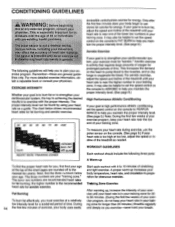
... using your heart rate as you to burn fat, adjust the speed and incline of stretching at a relatively cise program, do not keep your heart rate near the low end of the lower two numbers in your breath. WORKOUT GUIDELINES Each workout should include the following guidelines will help you exercise-never hold your training zone. It may also be helpful to set the speed control on the console...
... using your heart rate as you to burn fat, adjust the speed and incline of stretching at a relatively cise program, do not keep your heart rate near the low end of the lower two numbers in your breath. WORKOUT GUIDELINES Each workout should include the following guidelines will help you exercise-never hold your training zone. It may also be helpful to set the speed control on the console...
English Manual
Page 15
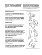
...15 counts, then relax. Repeat 3 times for several basic stretches is to make exercise a regular and enjoyable part of your everyday life. Bend your front leg, lean forward and move your hips toward your toes as far as possible. To cause further stretching of...form for each leg. Repeat 3 times. Stretches: Hamstrings, lower back and groin. 3 3. Hold for 15 counts, then relax. Inner Thigh Stretch Sit with the soles of the achilles tendons, bend your back leg as well. This will increase the flexibility of your muscles and will help to prevent post-exercise problems. Exercise...
...15 counts, then relax. Repeat 3 times for several basic stretches is to make exercise a regular and enjoyable part of your everyday life. Bend your front leg, lean forward and move your hips toward your toes as far as possible. To cause further stretching of...form for each leg. Repeat 3 times. Stretches: Hamstrings, lower back and groin. 3 3. Hold for 15 counts, then relax. Inner Thigh Stretch Sit with the soles of the achilles tendons, bend your back leg as well. This will increase the flexibility of your muscles and will help to prevent post-exercise problems. Exercise...
English Manual
Page 16
...; The PART NUMBER OF THE PART (see the EXPLODED DRAWING and PART LIST included in this manual) • The DESCRIPTION OF THE PART (see the EXPLODED DRAWiNG and PART LIST included in this SEARS TREADMILL EXERCISER, contact the nearest SEARS Service Center throughout the United States and SEARS will repair or replace the TREADMILL EXERCISER, free of charge. This warranty gives you specific legal rights, and you need to state. This warranty does not...
...; The PART NUMBER OF THE PART (see the EXPLODED DRAWING and PART LIST included in this manual) • The DESCRIPTION OF THE PART (see the EXPLODED DRAWiNG and PART LIST included in this SEARS TREADMILL EXERCISER, contact the nearest SEARS Service Center throughout the United States and SEARS will repair or replace the TREADMILL EXERCISER, free of charge. This warranty gives you specific legal rights, and you need to state. This warranty does not...

English Manual
Page 17
REMOVE THIS EXPLODED DRAWING AND PART LIST FROM THE MANUAL Save this EXPLODED DRAWING and PART LIST for future reference. 0• O Note: Specifications are subject to change without notice. For information about ordering replacement parts, see the back cover of the Users Manual.
REMOVE THIS EXPLODED DRAWING AND PART LIST FROM THE MANUAL Save this EXPLODED DRAWING and PART LIST for future reference. 0• O Note: Specifications are subject to change without notice. For information about ordering replacement parts, see the back cover of the Users Manual.

English Manual
Page 19
... 1 Speed Knob 65 031108 1 Incline Switch 66* 134324 1 Console 67 134326 1 Motor 68 135866 1 Motor Belt 69 129875 1 Incline Motor 70 124669 1 Power Cord 71 124695 1 Grommet 72 134329 1 Wire Harness 73 132315 1 7 1/2" Wire Tie 74 129004 2 Wire Harness Grommet 75 134331 2 Shock 76 132435 2 Base Extension 77 133584 1 Power Supply w/Clips 78 134333 1 Controller 79 138058 1 Incline Leg 80 132453 1 Belly Pan 81 136203 1 Endcap Plug 82 136880 1 Rear Roller Cover 83...
... 1 Speed Knob 65 031108 1 Incline Switch 66* 134324 1 Console 67 134326 1 Motor 68 135866 1 Motor Belt 69 129875 1 Incline Motor 70 124669 1 Power Cord 71 124695 1 Grommet 72 134329 1 Wire Harness 73 132315 1 7 1/2" Wire Tie 74 129004 2 Wire Harness Grommet 75 134331 2 Shock 76 132435 2 Base Extension 77 133584 1 Power Supply w/Clips 78 134333 1 Controller 79 138058 1 Incline Leg 80 132453 1 Belly Pan 81 136203 1 Endcap Plug 82 136880 1 Rear Roller Cover 83...

