
Owner's Manual
Page 1
AUDIO/VIDEO MULTI-CHANNEL RECEIVER RECEPTOR MULTICANAL DE AUDIO/VÍDEO VSX-920 Register your product on http://www.pioneerelectronics.com (US) http://www.pioneerelectronics.ca (Canada) · Protect your new investment The details of your... such as loss or theft. · Receive free tips, updates and service bulletins on your new product · Improve product development Your input helps us continue to design products that meet your needs. · Receive a free Pioneer newsletter Registered customers can opt in to receive a monthly newsletter. Operating Instructions Manual de ...
AUDIO/VIDEO MULTI-CHANNEL RECEIVER RECEPTOR MULTICANAL DE AUDIO/VÍDEO VSX-920 Register your product on http://www.pioneerelectronics.com (US) http://www.pioneerelectronics.ca (Canada) · Protect your new investment The details of your... such as loss or theft. · Receive free tips, updates and service bulletins on your new product · Improve product development Your input helps us continue to design products that meet your needs. · Receive a free Pioneer newsletter Registered customers can opt in to receive a monthly newsletter. Operating Instructions Manual de ...
Owner's Manual
Page 2
... connect the unit to operate the equipment. Increase the separation between the equipment and receiver. - Product Name: AUDIO/VIDEO MULTI-CHANNEL RECEIVER Model Number: VSX-920 Responsible Party Name: PIONEER ELECTRONICS (USA) INC. To prevent electromagnetic interference with the product may invalidate the ... time, read the following measures: - D3-4-2-1-3_A1_En WARNING Before plugging in a car or ship) and which the receiver is properly disposed of the FCC Rules. D8-10-1-2_A1_En FEDERAL COMMUNICATIONS COMMISSION DECLARATION OF CONFORMITY This device complies with ...
... connect the unit to operate the equipment. Increase the separation between the equipment and receiver. - Product Name: AUDIO/VIDEO MULTI-CHANNEL RECEIVER Model Number: VSX-920 Responsible Party Name: PIONEER ELECTRONICS (USA) INC. To prevent electromagnetic interference with the product may invalidate the ... time, read the following measures: - D3-4-2-1-3_A1_En WARNING Before plugging in a car or ship) and which the receiver is properly disposed of the FCC Rules. D8-10-1-2_A1_En FEDERAL COMMUNICATIONS COMMISSION DECLARATION OF CONFORMITY This device complies with ...
Owner's Manual
Page 4
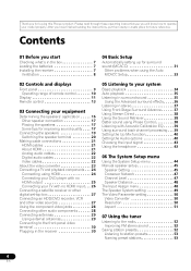
...28 Connecting other audio components 28 Connecting antennas 29 Using external antennas 29 Connecting to the front panel video terminal 30 Plugging in the receiver 30 05 Listening to your system Basic playback 34 Auto playback 35 Listening in surround sound 35 Using the Advanced surround effects . .... . . . 36 Listening in a safe place for buying this Pioneer product. Contents 01 Before you have finished reading the instructions, put them away in stereo 37 Using Front Stage Surround Advance 37 Using Stream...
...28 Connecting other audio components 28 Connecting antennas 29 Using external antennas 29 Connecting to the front panel video terminal 30 Plugging in the receiver 30 05 Listening to your system Basic playback 34 Auto playback 35 Listening in surround sound 35 Using the Advanced surround effects . .... . . . 36 Listening in a safe place for buying this Pioneer product. Contents 01 Before you have finished reading the instructions, put them away in stereo 37 Using Front Stage Surround Advance 37 Using Stream...
Owner's Manual
Page 5
...392,195; 7,272,567 & other components 58 Preset Code List 59 10 Other connections Connecting an iPod 62 Connecting your iPod to the receiver . . . . . 62 iPod playback 63 Watching photos and video content 64 About iPod 64 Connecting a USB device 65 Connecting ...Bluetooth wireless technology device with Your System 68 Listening to Satellite Radio 69 Connecting your SiriusConnectTM Tuner . . . 70 Listening to the receiver 65 Basic playback controls 65 Compressed audio compatibility 66 Bluetooth® ADAPTER for other U.S. and worldwide patents issued & pending. Product ...
...392,195; 7,272,567 & other components 58 Preset Code List 59 10 Other connections Connecting an iPod 62 Connecting your iPod to the receiver . . . . . 62 iPod playback 63 Watching photos and video content 64 About iPod 64 Connecting a USB device 65 Connecting ...Bluetooth wireless technology device with Your System 68 Listening to Satellite Radio 69 Connecting your SiriusConnectTM Tuner . . . 70 Listening to the receiver 65 Basic playback controls 65 Compressed audio compatibility 66 Bluetooth® ADAPTER for other U.S. and worldwide patents issued & pending. Product ...
Owner's Manual
Page 6
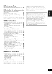
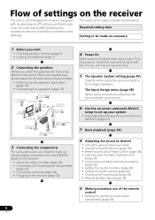
... using the surround back or front height speaker.) The Input Assign menu (page 48) (When using a digital connection from the BD/DVD player to the receiver. • About the video converter (page 23) • Connecting a TV and playback components (page 24) • Connecting antennas (page 29) • Plugging ... speakers Where you 've set the video input on the sound. It can be made as necessary 1 Before you start • Checking what's in the receiver (page 30) 6 En 4 Power On Make sure you place the speakers will have a big effect on your speakers as desired &#...
... using the surround back or front height speaker.) The Input Assign menu (page 48) (When using a digital connection from the BD/DVD player to the receiver. • About the video converter (page 23) • Connecting a TV and playback components (page 24) • Connecting antennas (page 29) • Plugging ... speakers Where you 've set the video input on the sound. It can be made as necessary 1 Before you start • Checking what's in the receiver (page 30) 6 En 4 Power On Make sure you place the speakers will have a big effect on your speakers as desired &#...
Owner's Manual
Page 7
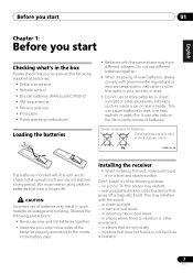
...;ais Italiano Nederlands Español Before you start 01 Chapter 1: Before you start Checking what's in the box Please check that you've received the following supplied accessories: • Setup microphone • Remote control • Dry cell batteries (AAA size IEC R03) x2 • ...the plus and minus sides of batteries. (Symbol examples for batteries) These symbols are to the marks in damp or wet areas - Installing the receiver • When installing this unit, make sure to leak, overheat, explode or catch fire. in places that have different voltages. in direct ...
...;ais Italiano Nederlands Español Before you start 01 Chapter 1: Before you start Checking what's in the box Please check that you've received the following supplied accessories: • Setup microphone • Remote control • Dry cell batteries (AAA size IEC R03) x2 • ...the plus and minus sides of batteries. (Symbol examples for batteries) These symbols are to the marks in damp or wet areas - Installing the receiver • When installing this unit, make sure to leak, overheat, explode or catch fire. in places that have different voltages. in direct ...
Owner's Manual
Page 8
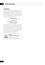
... hot when operating this unit, make sure the openings are provided for ventilation to protect the equipment from overheating. DO NOT TOUCH. CAUTION: HOT SURFACE. Receiver 40 cm (16 inches) Slot and openings in .) at the top). 01 Before you start Ventilation When installing this product continuously. 8 En If not enough...
... hot when operating this unit, make sure the openings are provided for ventilation to protect the equipment from overheating. DO NOT TOUCH. CAUTION: HOT SURFACE. Receiver 40 cm (16 inches) Slot and openings in .) at the top). 01 Before you start Ventilation When installing this product continuously. 8 En If not enough...
Owner's Manual
Page 9
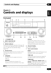
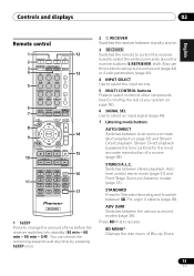
... name can be checked by selecting an input source.1 6 Character display See Display on page 11. 7 Tuner control buttons 4 Remote sensor Receives the signals from the remote control (see Operating range of this unit. DISPLAY Switches the display of remote control on page 10). 5 SPEAKERS... Radio (page 70). TUNER EDIT Use with TUNE /, PRESET / and ENTER to on page 20. CHANNEL RECEIVER VSX-920 TUNE TUNER EDIT PRESET ENTER MASTER VOLUME PHONES AUTO/DIRECT LISTENING MODE STEREO/ALC STANDARD ADV SURROUND iPod iPhone DIRECT CONTROL VIDEO INPUT USB...
... name can be checked by selecting an input source.1 6 Character display See Display on page 11. 7 Tuner control buttons 4 Remote sensor Receives the signals from the remote control (see Operating range of this unit. DISPLAY Switches the display of remote control on page 10). 5 SPEAKERS... Radio (page 70). TUNER EDIT Use with TUNE /, PRESET / and ENTER to on page 20. CHANNEL RECEIVER VSX-920 TUNE TUNER EDIT PRESET ENTER MASTER VOLUME PHONES AUTO/DIRECT LISTENING MODE STEREO/ALC STANDARD ADV SURROUND iPod iPhone DIRECT CONTROL VIDEO INPUT USB...

Owner's Manual
Page 10
... terminal on page 35) and Stream Direct playback. STEREO/ALC Switches between the various surround modes (page 36). 11 iPod iPhone DIRECT CONTROL Change the receiver's input to the iPod and enable iPod operations on the iPod (page 64). 12 iPod iPhone/USB terminal Use to connect your Apple iPod or... are connected, there is no sound output from the speakers (page 43). 10 Listening mode buttons AUTO/DIRECT Switches between the remote control and the receiver's remote sensor. • Direct sunlight or fluorescent light is shining onto the remote sensor. • The...
... terminal on page 35) and Stream Direct playback. STEREO/ALC Switches between the various surround modes (page 36). 11 iPod iPhone DIRECT CONTROL Change the receiver's input to the iPod and enable iPod operations on the iPod (page 64). 12 iPod iPhone/USB terminal Use to connect your Apple iPod or... are connected, there is no sound output from the speakers (page 43). 10 Listening mode buttons AUTO/DIRECT Switches between the remote control and the receiver's remote sensor. • Direct sunlight or fluorescent light is shining onto the remote sensor. • The...

Owner's Manual
Page 11
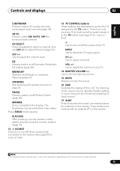
.... MEM Blinks when a radio station is registered. 8 PRESET information or input signal indicator Shows the preset number of the receiver is on page 35). 3 ST Lights when a stereo FM broadcast is being received in auto stereo mode. 4 TUNE Lights when a normal broadcast channel or SIRIUS channel is being... Indicates the speaker terminal, A and/or B, to which audio signal output is currently set (page 20). 6 Sleep timer indicator Lights when the receiver is in sleep mode (page 13). 7 Tuner/SIRIUS preset indicators PRESET Shows when a preset radio station is detected. HD Lights when a source ...
.... MEM Blinks when a radio station is registered. 8 PRESET information or input signal indicator Shows the preset number of the receiver is on page 35). 3 ST Lights when a stereo FM broadcast is being received in auto stereo mode. 4 TUNE Lights when a normal broadcast channel or SIRIUS channel is being... Indicates the speaker terminal, A and/or B, to which audio signal output is currently set (page 20). 6 Sleep timer indicator Lights when the receiver is in sleep mode (page 13). 7 Tuner/SIRIUS preset indicators PRESET Shows when a preset radio station is detected. HD Lights when a source ...
Owner's Manual
Page 13
...SELECT EQ 4 5 6 CH MIDNIGHT SPEAKERS 7 8 DIMMER CLR 0 / +10 D.ACCESS LEV 9 LEV ENTER PHASE CH SHIFT 14 15 16 17 RECEIVER 1 SLEEP Press to switch between 2 Pro Logic II options (page 35). STEREO/A.L.C. Controls and displays 02 English Deutsch Français Italiano Nederlands Espa&#...241;ol PRESET Remote control 1 RECEIVER SLEEP TV SOURCE CONTROL 2 3 RECEIVER INPUT SELECT INPUT 4 BD DVD TV 12 13 DVR CD CD-R CH 5 ADAPTER iPod USB VIDEO TUNER SIRIUS SIGNAL...
...SELECT EQ 4 5 6 CH MIDNIGHT SPEAKERS 7 8 DIMMER CLR 0 / +10 D.ACCESS LEV 9 LEV ENTER PHASE CH SHIFT 14 15 16 17 RECEIVER 1 SLEEP Press to switch between 2 Pro Logic II options (page 35). STEREO/A.L.C. Controls and displays 02 English Deutsch Français Italiano Nederlands Espa&#...241;ol PRESET Remote control 1 RECEIVER SLEEP TV SOURCE CONTROL 2 3 RECEIVER INPUT SELECT INPUT 4 BD DVD TV 12 13 DVR CD CD-R CH 5 ADAPTER iPod USB VIDEO TUNER SIRIUS SIGNAL...
Owner's Manual
Page 14
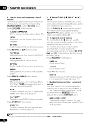
...mode is pressed. (For example MIDNIGHT, etc.) HDD*, DVD*, VCR* These buttons switch between the DTV and analog TV input modes for Pioneer flat panel TVs. 11 Number buttons and other buttons that can be accessed after you have selected the corresponding MULTI CONTROL button (BD, DVD,.... RETURN Confirm and exit the current menu screen. Also used to change the name (page 53). BAND Switches between the iPod controls and the receiver controls (page 64). 9 TUNE /, PRESET /), ENTER Use the arrow buttons when setting up your surround sound system (page...
...mode is pressed. (For example MIDNIGHT, etc.) HDD*, DVD*, VCR* These buttons switch between the DTV and analog TV input modes for Pioneer flat panel TVs. 11 Number buttons and other buttons that can be accessed after you have selected the corresponding MULTI CONTROL button (BD, DVD,.... RETURN Confirm and exit the current menu screen. Also used to change the name (page 53). BAND Switches between the iPod controls and the receiver controls (page 64). 9 TUNE /, PRESET /), ENTER Use the arrow buttons when setting up your surround sound system (page...
Owner's Manual
Page 15
... components connected to access: D.ACCESS After pressing, you only have selected. 15 En Use to adjust the level (page 47). Press SIRIUS first to the receiver (see page 57 for more on this unit. SB CH Press to adjust the channel level. Use to select ON, AUTO, OFF the surround back...
... components connected to access: D.ACCESS After pressing, you only have selected. 15 En Use to adjust the level (page 47). Press SIRIUS first to the receiver (see page 57 for more on this unit. SB CH Press to adjust the channel level. Use to select ON, AUTO, OFF the surround back...
Owner's Manual
Page 19
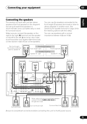
... B - Front height setting Front height right Front height left (L) terminal. Also make sure the positive and negative (+/-) terminals on the receiver match those on the left to stereo playback in the diagram) but using only one surround back speaker, connect it to complete all connections... used for surround sound. Connecting your equipment 03 English Deutsch Français Italiano Nederlands Español Connecting the speakers The receiver will work with a normal impedance between 6 Ω and 16 Ω. left Front right Powered subwoofer LINE LEVEL INPUT Center...
... B - Front height setting Front height right Front height left (L) terminal. Also make sure the positive and negative (+/-) terminals on the receiver match those on the left to stereo playback in the diagram) but using only one surround back speaker, connect it to complete all connections... used for surround sound. Connecting your equipment 03 English Deutsch Français Italiano Nederlands Español Connecting the speakers The receiver will work with a normal impedance between 6 Ω and 16 Ω. left Front right Powered subwoofer LINE LEVEL INPUT Center...
Owner's Manual
Page 21
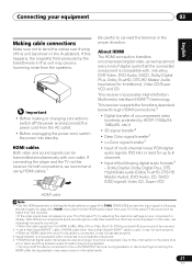
... possible when connected to a compatible component. 4 • HDMI format digital audio transmissions require a longer time to be recognized. This receiver incorporates High-Definition Multimedia Interface (HDMI™) technology. Important • Before making or changing connections, switch off the device connected to ...between audio formats or beginning playback. • Turning on page 40 to this, interruption in the proper direction. This receiver supports the functions described below for up to connect the terminal in the audio may cause noise or interrupted audio. 21 ...
... possible when connected to a compatible component. 4 • HDMI format digital audio transmissions require a longer time to be recognized. This receiver incorporates High-Definition Multimedia Interface (HDMI™) technology. Important • Before making or changing connections, switch off the device connected to ...between audio formats or beginning playback. • Turning on page 40 to this, interruption in the proper direction. This receiver supports the functions described below for up to connect the terminal in the audio may cause noise or interrupted audio. 21 ...
Owner's Manual
Page 22
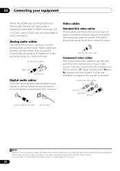
... to this way, interference between the signals is divided into the luminance (Y) signal and the color (PB and PR) signals and then output. In this receiver.1 Video cables Standard RCA video cables These cables are the most common type of video connection and are used to connect to get the best...
... to this way, interference between the signals is divided into the luminance (Y) signal and the color (PB and PR) signals and then output. In this receiver.1 Video cables Standard RCA video cables These cables are the most common type of video connection and are used to connect to get the best...
Owner's Manual
Page 23
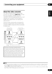
... sources are output from the component video input for the HDMI output are assigned to the same input function, the converter gives priority to the receiver's HDMI video outputs when connecting this video source.1 If several video components are 480i/576i, 480p/ 576p, 720p and 1080i. 1080p signal cannot be converted...
... sources are output from the component video input for the HDMI output are assigned to the same input function, the converter gives priority to the receiver's HDMI video outputs when connecting this video source.1 If several video components are 480i/576i, 480p/ 576p, 720p and 1080i. 1080p signal cannot be converted...
Owner's Manual
Page 24
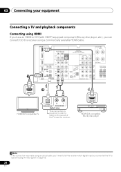
... Connecting using HDMI If you have an HDMI or DVI (with HDCP) equipped component (Blu-ray disc player, etc.), you can connect it to this receiver using an optical cable, you'll need to tell the receiver which digital input you connected the TV to the sound of the TV over the... receiver. HDMI OUT HDMI/DVI-compatible Blu-ray disc player Note 1 If the connection was made using a commercially available HDMI cable.1 IN BD SPEAKERS A R FRONT L DVD ...
... Connecting using HDMI If you have an HDMI or DVI (with HDCP) equipped component (Blu-ray disc player, etc.), you can connect it to this receiver using an optical cable, you'll need to tell the receiver which digital input you connected the TV to the sound of the TV over the... receiver. HDMI OUT HDMI/DVI-compatible Blu-ray disc player Note 1 If the connection was made using a commercially available HDMI cable.1 IN BD SPEAKERS A R FRONT L DVD ...
Owner's Manual
Page 25
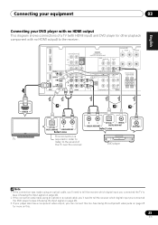
... no HDMI output This diagram shows connections of a TV (with HDMI input) and DVD player (or other playback component with no HDMI output) to the receiver.123 IN BD SPEAKERS A R FRONT L CENTER DVD TV/SAT CD-R/TAPE DVR/VCR L SUBWOOFER OUT PRE OUT R CD-R/TAPE DVR/VCR CD L ADAPTER PORT (OUTPUT... OUT Select one DVD player VIDEO OUT Note 1 If the connection was made using an optical or a coaxial cable, you'll need to tell the receiver which digital input you connected the TV to (see Choosing the input signal on this too. See Using the component video jacks on page 28...
... no HDMI output This diagram shows connections of a TV (with HDMI input) and DVD player (or other playback component with no HDMI output) to the receiver.123 IN BD SPEAKERS A R FRONT L CENTER DVD TV/SAT CD-R/TAPE DVR/VCR L SUBWOOFER OUT PRE OUT R CD-R/TAPE DVR/VCR CD L ADAPTER PORT (OUTPUT... OUT Select one DVD player VIDEO OUT Note 1 If the connection was made using an optical or a coaxial cable, you'll need to tell the receiver which digital input you connected the TV to (see Choosing the input signal on this too. See Using the component video jacks on page 28...
Owner's Manual
Page 26
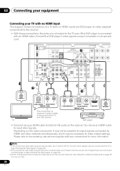
... listen to HD audio on the video component, it may not be possible to output signals connected by HDMI and other playback component) to the receiver.123 • With these too. R L OPTICAL COAXIAL ANALOG AUDIO OUT DIGITAL AUDIO OUT Select one This connection is required in order to listen ... using a composite or component cord. Connect the DVD player's video signals using an optical or a coaxial cable, you'll need to tell the receiver which digital input you connected the DVD player to (see Choosing the input signal on page 43). 2 If the connection was made using an optical...
... listen to HD audio on the video component, it may not be possible to output signals connected by HDMI and other playback component) to the receiver.123 • With these too. R L OPTICAL COAXIAL ANALOG AUDIO OUT DIGITAL AUDIO OUT Select one This connection is required in order to listen ... using a composite or component cord. Connect the DVD player's video signals using an optical or a coaxial cable, you'll need to tell the receiver which digital input you connected the DVD player to (see Choosing the input signal on page 43). 2 If the connection was made using an optical...


