Operating Instructions
Page 5
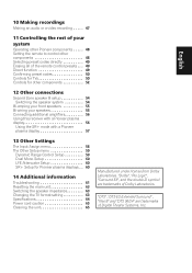
...Español 10 Making recordings Making an audio or a video recording . . . . . 47 11 Controlling the rest of your system Operating other Pioneer components . . . . . 48 Setting the remote to control other components 52 12 Other connections Second Zone speaker B setup 54 Switching the speaker ...menu 59 Dynamic Range Control Setup 59 Dual Mono Setup 60 LFE Attenuator Setup 60 SR+ Setup for Pioneer plasma displays . . 60 14 Additional information Troubleshooting 61 Resetting the main unit 63 Switching the speaker impedance 63 Changing the TV format setting 63 Specifications 64 Power...
...Español 10 Making recordings Making an audio or a video recording . . . . . 47 11 Controlling the rest of your system Operating other Pioneer components . . . . . 48 Setting the remote to control other components 52 12 Other connections Second Zone speaker B setup 54 Switching the speaker ...menu 59 Dynamic Range Control Setup 59 Dual Mono Setup 60 LFE Attenuator Setup 60 SR+ Setup for Pioneer plasma displays . . 60 14 Additional information Troubleshooting 61 Resetting the main unit 63 Switching the speaker impedance 63 Changing the TV format setting 63 Specifications 64 Power...
Operating Instructions
Page 27
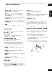
... near a device that is emitting infrared rays. • The receiver is operated simultaneously with another infrared remote control unit. 30 30 DOWN DOWN 7 m 27 En RESET - DIALOG E - Press to control other components connected to make dialog stand out when watching TV or a movie (page 32). Also use the +/- PRESET - Use to...
... near a device that is emitting infrared rays. • The receiver is operated simultaneously with another infrared remote control unit. 30 30 DOWN DOWN 7 m 27 En RESET - DIALOG E - Press to control other components connected to make dialog stand out when watching TV or a movie (page 32). Also use the +/- PRESET - Use to...

Operating Instructions
Page 48
... back a step, press RETURN. • After one component. OUT CONTROL IN Receiver CONTROL IN OUT Setting the remote to control other Pioneer components Many Pioneer components have SR CONTROL jacks which can be used to another component, you are cases where only certain functions may be controllable after assigning... sensor of one minute of analog audio or video jacks connected to link components together so that you also have to reset the receiver to the default settings (see Erasing all your components using the component's manufacturer preset code stored in tuner. 48 En
... back a step, press RETURN. • After one component. OUT CONTROL IN Receiver CONTROL IN OUT Setting the remote to control other Pioneer components Many Pioneer components have SR CONTROL jacks which can be used to another component, you are cases where only certain functions may be controllable after assigning... sensor of one minute of analog audio or video jacks connected to link components together so that you also have to reset the receiver to the default settings (see Erasing all your components using the component's manufacturer preset code stored in tuner. 48 En
Operating Instructions
Page 49
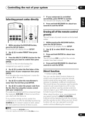
...presets This will be the manufacturer's name (for example, P for example, DVD 009). The remote LCD display shows SETUP. 2 Use / to select RESET then press ENTER. 3 Press and hold ENTER for the component you want to confirm the remote presets have been erased. 4 Press and hold RECEIVER ... time, using this remote control with your receiver to your component is on the receiver and then use direct function with the component type (for Pioneer). 5 Use / to select the manufacturer's name from the list then press ENTER. 6 Use / to control one . Note 1 You can't assign the RECEIVER ...
...presets This will be the manufacturer's name (for example, P for example, DVD 009). The remote LCD display shows SETUP. 2 Use / to select RESET then press ENTER. 3 Press and hold ENTER for the component you want to confirm the remote presets have been erased. 4 Press and hold RECEIVER ... time, using this remote control with your receiver to your component is on the receiver and then use direct function with the component type (for Pioneer). 5 Use / to select the manufacturer's name from the list then press ENTER. 6 Use / to control one . Note 1 You can't assign the RECEIVER ...
Operating Instructions
Page 61
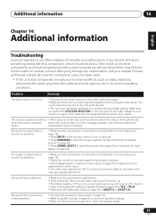
...source you won't be able to switch the unit on during this component, check the points below , ask your country or region, then reset the unit (page 63) before switching on . Refer to the instruction manual supplied with this time), off automatically. • The unit ...English Deutsch Français Italiano Nederlands Español Chapter 14: Additional information Troubleshooting Incorrect operations are often mistaken for your nearest Pioneer authorized independent service company to carry out repair work. • If the unit does not operate normally due to external effects ...
...source you won't be able to switch the unit on during this component, check the points below , ask your country or region, then reset the unit (page 63) before switching on . Refer to the instruction manual supplied with this time), off automatically. • The unit ...English Deutsch Français Italiano Nederlands Español Chapter 14: Additional information Troubleshooting Incorrect operations are often mistaken for your nearest Pioneer authorized independent service company to carry out repair work. • If the unit does not operate normally due to external effects ...
Operating Instructions
Page 63
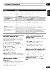
...Deutsch Français Italiano Nederlands Español Problem Remedy The SR cable is connected, but it 's connected to the right jack (see RESET? The System Setup screen doesn't appear. • When the receiver is displayed). USB ERR3 shows in when connecting a USB Important on page ... been made between the impedance settings: • SP 6 OHM - OK appears in the display, press ENTER. authorized service center or your nearest Pioneer device. shows in standby, switch to BURST.OFF by the receiver. • Try switching the receiver off . • Press DIMMER on the ...
...Deutsch Français Italiano Nederlands Español Problem Remedy The SR cable is connected, but it 's connected to the right jack (see RESET? The System Setup screen doesn't appear. • When the receiver is displayed). USB ERR3 shows in when connecting a USB Important on page ... been made between the impedance settings: • SP 6 OHM - OK appears in the display, press ENTER. authorized service center or your nearest Pioneer device. shows in standby, switch to BURST.OFF by the receiver. • Try switching the receiver off . • Press DIMMER on the ...

Service Manual
Page 29
... SS R953 100 R812 100 R952 100 R951 100 HREQ R840 100 C814 470p CH C815 0.1 YB R813 10k C813 stby C812 stby C811 stby VSX-816-K 6 7 V3D E L801 QTL1013 V37 IC802 IC802 TC7WU04FU TC7WU04FU (2/3) 8 8 (1/3) 2 6 5 3 4 4 C820 R815 1M YB 0.01 C819 R816 470 X801 VSS1171 20MHz YB 0.1 C818 C817 CH 8p C816... FST_1 59 SDI0_1 58 SDI1_1 PE8 57 PE9 56 PE10 55 MUTE 54 GNDCO 53 VDDCO 52 MODA 51 MODB 50 MODC 49 MODD 48 RESET 47 PINIT 46 EXTAL 45 VDDPD 44 GNDPD 43 GNDPP 42 41 CH C823 R826 stby R821 0 R817 100 470p C824 0.1 YB R818 stby C825...
... SS R953 100 R812 100 R952 100 R951 100 HREQ R840 100 C814 470p CH C815 0.1 YB R813 10k C813 stby C812 stby C811 stby VSX-816-K 6 7 V3D E L801 QTL1013 V37 IC802 IC802 TC7WU04FU TC7WU04FU (2/3) 8 8 (1/3) 2 6 5 3 4 4 C820 R815 1M YB 0.01 C819 R816 470 X801 VSS1171 20MHz YB 0.1 C818 C817 CH 8p C816... FST_1 59 SDI0_1 58 SDI1_1 PE8 57 PE9 56 PE10 55 MUTE 54 GNDCO 53 VDDCO 52 MODA 51 MODB 50 MODC 49 MODD 48 RESET 47 PINIT 46 EXTAL 45 VDDPD 44 GNDPD 43 GNDPP 42 41 CH C823 R826 stby R821 0 R817 100 470p C824 0.1 YB R818 stby C825...

Service Manual
Page 69
... W127 VDD1 W108 CD S459 CDR/TAPE/MD S465 W100 W101 W118 TUNER S464 W120 XM S453 W107 VDD1 C442 1 VSS0 2 SI1 3 SO1 4 SCK1 5 NC 6 RESET 7 VDD 8 VPP(IC) 9 NC W102 VDD1 W104 AUX S452 W106 W105 VSS1 IPOD S451 1 ENA 2 ENB 3 GNDU 4 FEN B 5 FEN A 6 KEY4-2 7 VOL_LED W103 VSS1 R467 R466...-2 7 VOL_LED S513 180 170 E 160 R CMKM-P3X 150 7 511 (XNP3100-C) 140 R. ENCODER ASSY 120 Y F 250 260 270 280 290 300 310 320 330 340 X KL VSX-816-K 69 5 6 7 8 ENCODER ASSY XWZ 4055 130 L R.
... W127 VDD1 W108 CD S459 CDR/TAPE/MD S465 W100 W101 W118 TUNER S464 W120 XM S453 W107 VDD1 C442 1 VSS0 2 SI1 3 SO1 4 SCK1 5 NC 6 RESET 7 VDD 8 VPP(IC) 9 NC W102 VDD1 W104 AUX S452 W106 W105 VSS1 IPOD S451 1 ENA 2 ENB 3 GNDU 4 FEN B 5 FEN A 6 KEY4-2 7 VOL_LED W103 VSS1 R467 R466...-2 7 VOL_LED S513 180 170 E 160 R CMKM-P3X 150 7 511 (XNP3100-C) 140 R. ENCODER ASSY 120 Y F 250 260 270 280 290 300 310 320 330 340 X KL VSX-816-K 69 5 6 7 8 ENCODER ASSY XWZ 4055 130 L R.

Service Manual
Page 112
... DISP CLK/OSD CLK 7 P90/TB0IN/CLK3 GND 8 BYTE CNVSS 9 CNVss I2C CLK EEPROM 10 P87/XCIN I2C DT EEPROM 11 P86/XCOUT XRESET 12 RESET XOUT 13 XOUT GND 14 VSS XIN 15 XIN D 5V 16 VCC NMI 17 P85/NMI ACIN(WAKEUP) 18 P84/INT2 USB TREQ 19 P83... DSP MODE DSP HREQ BUSY DSP SS DSP RST DSP CLK DSP DO DSP DI 232C CTS CLK RX(SR+/iPod) TX(SR+/iPod) F 112 VSX-816-K 1 2 3 4
... DISP CLK/OSD CLK 7 P90/TB0IN/CLK3 GND 8 BYTE CNVSS 9 CNVss I2C CLK EEPROM 10 P87/XCIN I2C DT EEPROM 11 P86/XCOUT XRESET 12 RESET XOUT 13 XOUT GND 14 VSS XIN 15 XIN D 5V 16 VCC NMI 17 P85/NMI ACIN(WAKEUP) 18 P84/INT2 USB TREQ 19 P83... DSP MODE DSP HREQ BUSY DSP SS DSP RST DSP CLK DSP DO DSP DI 232C CTS CLK RX(SR+/iPod) TX(SR+/iPod) F 112 VSX-816-K 1 2 3 4

Service Manual
Page 113
... to display u-com/OSD IC I/O clock for I2C communication with EEPROM IC I/O data for I2C communication with DIR/DAC I/O DSP ASSY I/O Reset signal for communication with EEPROM IC I no use I/O AC pulse in MCACC I/O DSP error detect signal I/O Mode select of DSP (ROM/...Data input signal for communication with DSP I/O Clock signal for communication with DSP and DIR I/O Reset signal for DSP I/O Strobe select signal to main u-com I/O wake up signal from TCC760 to DSP I/O Use it in I/O Request from display u-com I /O DIR X'tal change VSX-816-K 5 6 7 8 A B C D E F 113 5 6 7 8 •...
... to display u-com/OSD IC I/O clock for I2C communication with EEPROM IC I/O data for I2C communication with DIR/DAC I/O DSP ASSY I/O Reset signal for communication with EEPROM IC I no use I/O AC pulse in MCACC I/O DSP error detect signal I/O Mode select of DSP (ROM/...Data input signal for communication with DSP I/O Clock signal for communication with DSP and DIR I/O Reset signal for DSP I/O Strobe select signal to main u-com I/O wake up signal from TCC760 to DSP I/O Use it in I/O Request from display u-com I /O DIR X'tal change VSX-816-K 5 6 7 8 A B C D E F 113 5 6 7 8 •...

Service Manual
Page 114
...RDS clock in signal/XM Lowspeed RDS DT/Link ACTIVE(XM) I/O RDSdata in signal/XM Link Active RDS FM+/XM RST I /O data input from USB VSX-816-K 2 3 4 FM : Low, AM:High WAKE UPB(XM) I/O XMDT for XM AMUTE I/O System mute RY_B I/O Speaker B relay-on /off ...OSD RST I/O OSD CS I/O DECO MUTE I/O 1st DSP detect port XPROTECT I /O Amplifier DC detection. AVCC connects with VCC. For 6 ohm spk impedance: L XMDACRST I/O RESET of 2chDAC for communication XM Signal Sw I /O lnput 2 to L. H always. XM Fs I/O XM SIMUKE1 I/O lnput 1 to switch region SIMUKE2 I /O CLK,DT, etc...
...RDS clock in signal/XM Lowspeed RDS DT/Link ACTIVE(XM) I/O RDSdata in signal/XM Link Active RDS FM+/XM RST I /O data input from USB VSX-816-K 2 3 4 FM : Low, AM:High WAKE UPB(XM) I/O XMDT for XM AMUTE I/O System mute RY_B I/O Speaker B relay-on /off ...OSD RST I/O OSD CS I/O DECO MUTE I/O 1st DSP detect port XPROTECT I /O Amplifier DC detection. AVCC connects with VCC. For 6 ohm spk impedance: L XMDACRST I/O RESET of 2chDAC for communication XM Signal Sw I /O lnput 2 to L. H always. XM Fs I/O XM SIMUKE1 I/O lnput 1 to switch region SIMUKE2 I /O CLK,DT, etc...

Service Manual
Page 116
... I/O VOLUME JOG1(-) I/O VOLUME JOG1(+) I/O NC I/O MCACC LED output I /O POWER LED output O Display O Display O Display O Display O Display O Display O Display O Display O Display VSX-816-K 2 3 4 H:ON, L:OFF. ground potential for checker I/O output wakeup signal to A/D converter - L:detected, H:No detect I /O Pin Function - 1 • Pin Function A No.... Port 1 VDD1 2 VSS1 3 X1 4 X2 5 IC(VPP) 6 RESET 7 P27/SCK1 8 P26/SI1 9 P25/SO1 B 10 P24/BUSY 11 P23 12 P22 13 P21/SO3 14 P20/SCK3 15 P00/INTP0 16 P01...
... I/O VOLUME JOG1(-) I/O VOLUME JOG1(+) I/O NC I/O MCACC LED output I /O POWER LED output O Display O Display O Display O Display O Display O Display O Display O Display O Display VSX-816-K 2 3 4 H:ON, L:OFF. ground potential for checker I/O output wakeup signal to A/D converter - L:detected, H:No detect I /O Pin Function - 1 • Pin Function A No.... Port 1 VDD1 2 VSS1 3 X1 4 X2 5 IC(VPP) 6 RESET 7 P27/SCK1 8 P26/SI1 9 P25/SO1 B 10 P24/BUSY 11 P23 12 P22 13 P21/SO3 14 P20/SCK3 15 P00/INTP0 16 P01...

Service Manual
Page 126
... 124 EXINT3/GPIO_A15 125 XD0 126 XD1 127 XD2 128 XD3 I/O Pin Function I JTAG test clock for ARM940T I/O JTAG serial data output for ARM940T I JTAG reset signal for ARM940T, active low I/O Serial data output 0 / GPIO_A[0] I/O Serial clock input 0 / GPIO_A[1] I/O Serial frame 0 / GPIO_A[2] I/O Serial data input 0 / GPIO_A[3] I/O Serial data output 1 / GPIO_A[4] −...] I/O External bus data bit [0] I/O External bus data bit [1] I/O External bus data bit [2] I Enable input: 4618 active low, 4618- active high I P-channel MOS FET source F 126 VSX-816-K 1 2 3 4
... 124 EXINT3/GPIO_A15 125 XD0 126 XD1 127 XD2 128 XD3 I/O Pin Function I JTAG test clock for ARM940T I/O JTAG serial data output for ARM940T I JTAG reset signal for ARM940T, active low I/O Serial data output 0 / GPIO_A[0] I/O Serial clock input 0 / GPIO_A[1] I/O Serial frame 0 / GPIO_A[2] I/O Serial data input 0 / GPIO_A[3] I/O Serial data output 1 / GPIO_A[4] −...] I/O External bus data bit [0] I/O External bus data bit [1] I/O External bus data bit [2] I Enable input: 4618 active low, 4618- active high I P-channel MOS FET source F 126 VSX-816-K 1 2 3 4
Service Manual
Page 141
...ON/OFF - If the signal is operated simultaneously with another infrared remote control unit. 30 30 DOWN DOWN 23 ft (7m) F VSX-816-K 141 5 6 7 8 Direct playback bypasses the tone controls and any other components (see Controlling the rest of remote control The ... make these buttons can then use +/- See Direct function. SUBTITLE - Displays/changes the subtitles included in multilingual DVD-Video discs. RESET - to select an Acoustic Calibration EQ setting. INPUT SELECT - Stops recording. DIALOG E - Changes the audio language or channel on...
...ON/OFF - If the signal is operated simultaneously with another infrared remote control unit. 30 30 DOWN DOWN 23 ft (7m) F VSX-816-K 141 5 6 7 8 Direct playback bypasses the tone controls and any other components (see Controlling the rest of remote control The ... make these buttons can then use +/- See Direct function. SUBTITLE - Displays/changes the subtitles included in multilingual DVD-Video discs. RESET - to select an Acoustic Calibration EQ setting. INPUT SELECT - Stops recording. DIALOG E - Changes the audio language or channel on...
