Service Manual
Page 1
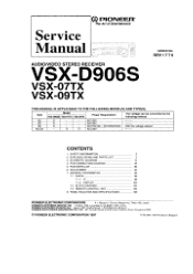
SCHEMATIC DIAGRAM 12 4. ADJUSTMENT 93 7. OD PIONEER® The Art of Entertainment Service Manual AUDIONIDEO STEREO RECEIVER VSX-D906S VSX-07TX VSX-09TX ORDER NO. PCB CONNECTION DIAGRAM 49 5. Haven 1087, Keetberglaan 1, 9120 Melsele, Belgium PIONEER ELECTRONICS ASIACENTRE PTE. PANEL FACILITIES AND SPECIFICATIONS 108 PIONEER ELECTRONIC CORPORATION 4-1, Meguro 1-Chome, Meguro-ku, Tokyo 153, Japan PIONEER ELECTRONICS SERVICE, INC. Type Model VSX-D906S VSX-07TX VSX-09TX Power Requirement The voltage can be converted by the following method...
SCHEMATIC DIAGRAM 12 4. ADJUSTMENT 93 7. OD PIONEER® The Art of Entertainment Service Manual AUDIONIDEO STEREO RECEIVER VSX-D906S VSX-07TX VSX-09TX ORDER NO. PCB CONNECTION DIAGRAM 49 5. Haven 1087, Keetberglaan 1, 9120 Melsele, Belgium PIONEER ELECTRONICS ASIACENTRE PTE. PANEL FACILITIES AND SPECIFICATIONS 108 PIONEER ELECTRONIC CORPORATION 4-1, Meguro 1-Chome, Meguro-ku, Tokyo 153, Japan PIONEER ELECTRONICS SERVICE, INC. Type Model VSX-D906S VSX-07TX VSX-09TX Power Requirement The voltage can be converted by the following method...
Service Manual
Page 2
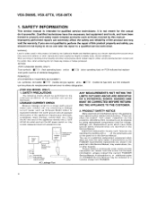
.... The use of a substitute replacement component which dose not have been trained to , or additional copies of the appliance directly into a 120V AC 60 Hz outlet and turn the AC power switch on PCB indicate that replace- For the latest information, always consult the current PIONEER Service Manual. VSX-D906S, VSX-07TX, VSX-09TX 1. SAFETY PRECAUTIONS The following check should not be obtained by connecting a leakage...
.... The use of a substitute replacement component which dose not have been trained to , or additional copies of the appliance directly into a 120V AC 60 Hz outlet and turn the AC power switch on PCB indicate that replace- For the latest information, always consult the current PIONEER Service Manual. VSX-D906S, VSX-07TX, VSX-09TX 1. SAFETY PRECAUTIONS The following check should not be obtained by connecting a leakage...
Service Manual
Page 3
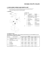
... used Not used ARC7158 Not used Not used ARR - 003 Not used Not used Not used Not used Description Parts No. 4 15' (KC type only) NSP 1 FM Antenna ADH1015 2 Alkaline Dry Cell Battenes (L126. AA) AEX 1007 3 Operating Instructions Sec Contrast table (2) 4 Sub Instruction Manual ISC (English) ARH7022 5 Sub Instruction Manual AC-3 (English) ARH7023 11-13 10 14 NSP NSP 6 Warranty Card 7 AM Loop Antenna 8 Remote Control Unit 9 Front Pad 10 Rear...
... used Not used ARC7158 Not used Not used ARR - 003 Not used Not used Not used Not used Description Parts No. 4 15' (KC type only) NSP 1 FM Antenna ADH1015 2 Alkaline Dry Cell Battenes (L126. AA) AEX 1007 3 Operating Instructions Sec Contrast table (2) 4 Sub Instruction Manual ISC (English) ARH7022 5 Sub Instruction Manual AC-3 (English) ARH7023 11-13 10 14 NSP NSP 6 Warranty Card 7 AM Loop Antenna 8 Remote Control Unit 9 Front Pad 10 Rear...

Service Manual
Page 7
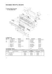
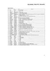
... /SD VSX-07TX /KU/CA VSX-09TX Remarks /KU/CA I AUDIO ASSY NSF 2 AUDIONIDEO ASSY 3 VIDEO ASSY NSF' 4 PRE-OUT & SR ASSY 5 S-VIDEO ASSY AWZ8763 AWZ8766 AWZ8769 AWZ8774 AWZ8808 AWZ8763 AWZ8766 AWZ8769 AWZ8774 AWZ8808 AWZ8763 AWZ8766 AWZ8769 AWZ8774 AWZ8808 AWZ8718 AWZ8719 AWZ8720 AWZ8722 AWZ872 I AWZ8762 AWZ8765 AWZ8768 AWZ8773 AWZ877I NSF' NSP 6 SP TERMINAL ASSY 7 PRIMARY ASSY 9 POWER SUPPLY...
... /SD VSX-07TX /KU/CA VSX-09TX Remarks /KU/CA I AUDIO ASSY NSF 2 AUDIONIDEO ASSY 3 VIDEO ASSY NSF' 4 PRE-OUT & SR ASSY 5 S-VIDEO ASSY AWZ8763 AWZ8766 AWZ8769 AWZ8774 AWZ8808 AWZ8763 AWZ8766 AWZ8769 AWZ8774 AWZ8808 AWZ8763 AWZ8766 AWZ8769 AWZ8774 AWZ8808 AWZ8718 AWZ8719 AWZ8720 AWZ8722 AWZ872 I AWZ8762 AWZ8765 AWZ8768 AWZ8773 AWZ877I NSF' NSP 6 SP TERMINAL ASSY 7 PRIMARY ASSY 9 POWER SUPPLY...
Service Manual
Page 10
... 4--21 16 15 21 20 12 (1) PARTS LIST Mark No. Symbol & Description VSX-D906S/KU Part No. See Contrast table (2) AMB7432 VAM1032 AAD7377 AAD7378 6 Himelon Sheet 7 LED Lens 8 Standby Lens 9 Display Panel 10 FL Filter AED7019 AAK7377 AAK7378 See Contrast table (2) AAK7382 16 Enter Button 17 Regular Button 18 Function Button 19 Input Button 20 Front Panel AAD7379 AAD7380 AAD7381 AAD7382 AMB7433 (2) CONTRAST...
... 4--21 16 15 21 20 12 (1) PARTS LIST Mark No. Symbol & Description VSX-D906S/KU Part No. See Contrast table (2) AMB7432 VAM1032 AAD7377 AAD7378 6 Himelon Sheet 7 LED Lens 8 Standby Lens 9 Display Panel 10 FL Filter AED7019 AAK7377 AAK7378 See Contrast table (2) AAK7382 16 Enter Button 17 Regular Button 18 Function Button 19 Input Button 20 Front Panel AAD7379 AAD7380 AAD7381 AAD7382 AMB7433 (2) CONTRAST...

Service Manual
Page 11
... 4 POWER SWITCH ASSY 5 FFC 29P AWZ8724 AWZ8723 AWZ8725 AWZ8784 ADD7060 6 Himelon Sheet 7 LED Lens 8 Standby Lens 9 Display Panel 10 FL Filter AED7019 AAK7377 AAK7378 AAK7379 AAK738 I 11 Volume Ring 12 Sub Panel 13 Name Plate 14 Power Button 15 5-Action Button AAK7384 AMB7437 VAM1032 AAD7377 AAD7378 12 Mark No. 16 17 18 19 20 Description Enter Button PVC Panel Function Button Input Button Front Panel (VSX-07TX) 20 Front Panel (VSX-09TX...
... 4 POWER SWITCH ASSY 5 FFC 29P AWZ8724 AWZ8723 AWZ8725 AWZ8784 ADD7060 6 Himelon Sheet 7 LED Lens 8 Standby Lens 9 Display Panel 10 FL Filter AED7019 AAK7377 AAK7378 AAK7379 AAK738 I 11 Volume Ring 12 Sub Panel 13 Name Plate 14 Power Button 15 5-Action Button AAK7384 AMB7437 VAM1032 AAD7377 AAD7378 12 Mark No. 16 17 18 19 20 Description Enter Button PVC Panel Function Button Input Button Front Panel (VSX-07TX) 20 Front Panel (VSX-09TX...
Service Manual
Page 12
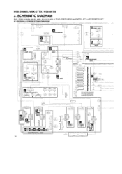
... S-VIDEO ASSY PRE-OUT & SR ASSY DOLBY DIGITAL ASSY 12 FAN 0167012 POWER SWITCH ASSY V-AMP ASSY 02 060 SD AND KU/CA TYPES MASTER VR ASSY JCL -15515) KU AND KC TYPES (ai5m5)+ 215215 SD AND KU/CA TYPES H1 92 51063 0505 VOLTAGE AMP ASSY 1' 25 230 215 A15 1 51063-03051 6.'-150 P LIMITTER Ir/r; SCHEMATIC DIAGRAM Note : When ordering service parts...
... S-VIDEO ASSY PRE-OUT & SR ASSY DOLBY DIGITAL ASSY 12 FAN 0167012 POWER SWITCH ASSY V-AMP ASSY 02 060 SD AND KU/CA TYPES MASTER VR ASSY JCL -15515) KU AND KC TYPES (ai5m5)+ 215215 SD AND KU/CA TYPES H1 92 51063 0505 VOLTAGE AMP ASSY 1' 25 230 215 A15 1 51063-03051 6.'-150 P LIMITTER Ir/r; SCHEMATIC DIAGRAM Note : When ordering service parts...
Service Manual
Page 13
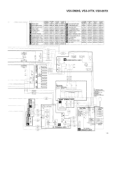
... El AUDIO/VIDEO ASSY VSX-3906S VSX-D906S /KU AND KC ,'SD VSX-07TX /KU/CA VSX-09TX (KU/CA AWZ8763 , AWZ8763 AWZ8718 AWZ8762 AWZ8766 AWZ8766 AWZ8719 AWZ8765 al VOLTAGE AMP ASSY in AW28769 AWZ8769 AWZ8720 AWZ8766 SP TERMINAL ASSY AWZ8727 AWZ8788 AWZ8727 AWZ8727 Ig S-VIDEO ASSY 9 AVVZ8808 AVVZ8808 AWZ8721 AWZ8771 POWER SUPPLY ASSY AWZ8792 AWZ8870 AVVZ8729 , AWZ8729 9 E VR ASSY MASTER...
... El AUDIO/VIDEO ASSY VSX-3906S VSX-D906S /KU AND KC ,'SD VSX-07TX /KU/CA VSX-09TX (KU/CA AWZ8763 , AWZ8763 AWZ8718 AWZ8762 AWZ8766 AWZ8766 AWZ8719 AWZ8765 al VOLTAGE AMP ASSY in AW28769 AWZ8769 AWZ8720 AWZ8766 SP TERMINAL ASSY AWZ8727 AWZ8788 AWZ8727 AWZ8727 Ig S-VIDEO ASSY 9 AVVZ8808 AVVZ8808 AWZ8721 AWZ8771 POWER SUPPLY ASSY AWZ8792 AWZ8870 AVVZ8729 , AWZ8729 9 E VR ASSY MASTER...

Service Manual
Page 47
...VSX-D906S, VSX-07TX, VSX-09TX FL HU_DER 8N41429-8 5 I6 7 8 9 23 2 5212. 48 94A 6855 1K R055 Pre... RESET DIRECT LOUDNESS 5815: DRC S822 : BASS+ 5816 : SYS SET UP... S823 : THE - 5817: MEMORY S824 : TRE + S818 : MPX S825 : AM S819 : SP A S826 : FM S820: SP B S827: LIST IN S821 : BASS - I 'D -W.- 02- LED morin 14 DRIVER...ohm 1/4w ±55 tolerance un oche -wise noted Kr 4ohm. CB18 IR AU/0_A 21 •H.c „-- III e824 - 7/2,-+- PROT O HP. FL U-COM ASSY 8801 : DVD/TV S802 : LD/SAT S803 : VIDEO S804 : CD S805 : TUNER S806 : TAPE2 S807 : PHONO...
...VSX-D906S, VSX-07TX, VSX-09TX FL HU_DER 8N41429-8 5 I6 7 8 9 23 2 5212. 48 94A 6855 1K R055 Pre... RESET DIRECT LOUDNESS 5815: DRC S822 : BASS+ 5816 : SYS SET UP... S823 : THE - 5817: MEMORY S824 : TRE + S818 : MPX S825 : AM S819 : SP A S826 : FM S820: SP B S827: LIST IN S821 : BASS - I 'D -W.- 02- LED morin 14 DRIVER...ohm 1/4w ±55 tolerance un oche -wise noted Kr 4ohm. CB18 IR AU/0_A 21 •H.c „-- III e824 - 7/2,-+- PROT O HP. FL U-COM ASSY 8801 : DVD/TV S802 : LD/SAT S803 : VIDEO S804 : CD S805 : TUNER S806 : TAPE2 S807 : PHONO...

Service Manual
Page 51
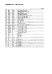
... AWK7364 AWZ87I7 AWZ8716 AWK7364 AWZ8717 AWZ8716 DOLBY DIGITAL ASSY FM/AM TUNER MODULE IAMITTER ASSY AWX7038 AXQ7219 Not used AWX7038 AXQ7219 Not used AWX7038 AXQ1012 AWK7406 AWX7038 AXQ7219 AWK7406 AWX7038 AXQ7219 AWK7406 VSX-13906S, VSX-07TX, VSX-09TX 5. TRANS TERMINAL ASSY - Ex.1 When there are 2 effective digits (any digit apart from 0), such as 560 ohm and 47k ohm (tolerance is shown by "NSP...
... AWK7364 AWZ87I7 AWZ8716 AWK7364 AWZ8717 AWZ8716 DOLBY DIGITAL ASSY FM/AM TUNER MODULE IAMITTER ASSY AWX7038 AXQ7219 Not used AWX7038 AXQ7219 Not used AWX7038 AXQ1012 AWK7406 AWX7038 AXQ7219 AWK7406 AWX7038 AXQ7219 AWK7406 VSX-13906S, VSX-07TX, VSX-09TX 5. TRANS TERMINAL ASSY - Ex.1 When there are 2 effective digits (any digit apart from 0), such as 560 ohm and 47k ohm (tolerance is shown by "NSP...
Service Manual
Page 64
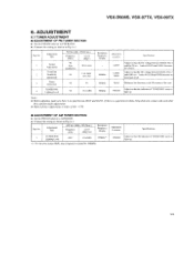
... adjustment 98 Low input (0 to AM BAND. • Connect the wiring as shown in Fig. 6-1. leads of C6224 and O6261) becomes 0V±50mV. Votes: • Before adjusting, make adjustments. • Make indicator adjustments in order ofAM FM. • ADJUSTMENT OF AM TUNER SECTION • Set the FM/AM selector to 30) Stereo 3 Distortion 98 80 TUNED IND. 4 Lighting Level 98 15 (±2dB ) Reception Frequency Display...
... adjustment 98 Low input (0 to AM BAND. • Connect the wiring as shown in Fig. 6-1. leads of C6224 and O6261) becomes 0V±50mV. Votes: • Before adjusting, make adjustments. • Make indicator adjustments in order ofAM FM. • ADJUSTMENT OF AM TUNER SECTION • Set the FM/AM selector to 30) Stereo 3 Distortion 98 80 TUNED IND. 4 Lighting Level 98 15 (±2dB ) Reception Frequency Display...
Service Manual
Page 68
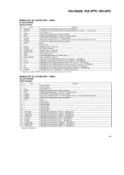
... 0 Sets to "H" when data are transferred to the microprocessor in stereo). 37 GND AVSS GND. 38 RST RST I DSP overload detect. GND. 42 TX TX 0 Open. 43 TEX TEX I Fan temperature input. VSX-D906S, VSX-07TX, VSX-09TX • Pin Function No. H :connect 10 LFE LED PE6/PWM 0 LED lights up during playback of AC3 or partial playback of AC3 microcomputer. 25 TUNED...
... 0 Sets to "H" when data are transferred to the microprocessor in stereo). 37 GND AVSS GND. 38 RST RST I DSP overload detect. GND. 42 TX TX 0 Open. 43 TEX TEX I Fan temperature input. VSX-D906S, VSX-07TX, VSX-09TX • Pin Function No. H :connect 10 LFE LED PE6/PWM 0 LED lights up during playback of AC3 or partial playback of AC3 microcomputer. 25 TUNED...
Service Manual
Page 69
...TC system, M66311 control. O Strobe output for sub room. O Segment output 15. O Tinting output 10. O Mute for TC9299. O Strobe output for TC9163. BU4094, TC9210. O Strobe output for TC9210. O Strobe output for AC3. O IC module reset output for M66311. O Master Volume (electrically operated) UP output. O Segment output 8/KEY scan output 3. O Segment output 10/KEY scan output 1. O Segment output 16. O Segment output 20. O Timing output 9. O Timing output 6. O Tuner mute ON/OFF. TC system, M6631 I /O Function O Clock for [C. O KEY...
...TC system, M66311 control. O Strobe output for sub room. O Segment output 15. O Tinting output 10. O Mute for TC9299. O Strobe output for TC9163. BU4094, TC9210. O Strobe output for TC9210. O Strobe output for AC3. O IC module reset output for M66311. O Master Volume (electrically operated) UP output. O Segment output 8/KEY scan output 3. O Segment output 10/KEY scan output 1. O Segment output 16. O Segment output 20. O Timing output 9. O Timing output 6. O Tuner mute ON/OFF. TC system, M6631 I /O Function O Clock for [C. O KEY...
Service Manual
Page 70
... up when function is PHONO. LEI) lights up . L : LED lights up . L LED lights up . L : LED lights up when function is VCR2. LED lights up . Reset input. CND. Fixed to "L" (output enabled). H . H . Output enable/disable signal, L Fixed to "H". After that , fixed to "1-1". Clock line for communications with microcomputer. Not used . LED lights up . L LED lights up when function is detected during decoding of M66311 (Set data to `L" when the power switch is received. VSX-D906S, VSX-07TX, VSX-09TX...
... up when function is PHONO. LEI) lights up . L : LED lights up . L LED lights up . L : LED lights up when function is VCR2. LED lights up . Reset input. CND. Fixed to "L" (output enabled). H . H . Output enable/disable signal, L Fixed to "H". After that , fixed to "1-1". Clock line for communications with microcomputer. Not used . LED lights up . L LED lights up when function is detected during decoding of M66311 (Set data to `L" when the power switch is received. VSX-D906S, VSX-07TX, VSX-09TX...
Service Manual
Page 79
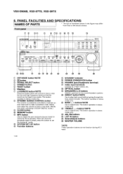
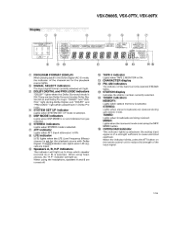
...stereo mode only. When the received broadcast signal is low to a low level. (Works only when operating in the figure may differ from that the sound can be heard more easily. This button operates in stereo mode only. This button operates in stereo mode only. EC) O • A [ a) t AIIII I - SYSTEM SET UP button Function buttons STANDBY indicator POWER STANDBY/ON button PHONES jack (Headphone terminal) Video input terminals Connect to adjust tone. Front panel 1T T® OD PIONISF_11. BASS -, + buttons*NOTE Use to a video camera, etc. TREBLE -, + buttons*NOTE Use to set...
...stereo mode only. When the received broadcast signal is low to a low level. (Works only when operating in the figure may differ from that the sound can be heard more easily. This button operates in stereo mode only. This button operates in stereo mode only. EC) O • A [ a) t AIIII I - SYSTEM SET UP button Function buttons STANDBY indicator POWER STANDBY/ON button PHONES jack (Headphone terminal) Video input terminals Connect to adjust tone. Front panel 1T T® OD PIONISF_11. BASS -, + buttons*NOTE Use to a video camera, etc. TREBLE -, + buttons*NOTE Use to set...
Service Manual
Page 80
... DISPLAY L C R O O O LS S Rs O O O LFE CD SIGNAL SELECT AC-3 RF DIGITAL ANALOG AUTO SP> ABH.P I TAPE 21 DOLBY > DIGITAL PRO LOGIC GO CO irk) Oki UM. 01.@71`I. SYSTEM SET UP DSP MODE JAZZ HALL DANCE THEATER-12 STEREO DIREC1> ON LOUD> ON TONE CONT. When the indicator blinks, press the ATT button on and indicates the type selected. C) ATT indicator Lights when ATT (input attenuator) is ON. ® LFE indicator [LFE] lights when the LFE (Low Frequency Effects) channel...
... DISPLAY L C R O O O LS S Rs O O O LFE CD SIGNAL SELECT AC-3 RF DIGITAL ANALOG AUTO SP> ABH.P I TAPE 21 DOLBY > DIGITAL PRO LOGIC GO CO irk) Oki UM. 01.@71`I. SYSTEM SET UP DSP MODE JAZZ HALL DANCE THEATER-12 STEREO DIREC1> ON LOUD> ON TONE CONT. When the indicator blinks, press the ATT button on and indicates the type selected. C) ATT indicator Lights when ATT (input attenuator) is ON. ® LFE indicator [LFE] lights when the LFE (Low Frequency Effects) channel...

Service Manual
Page 81
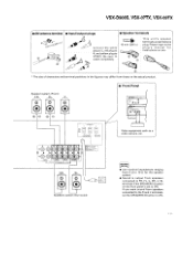
... power cord from the wall outlet. • For better reception of signals, use an FM external antenna. • When AM broadcast reception is poor Connect a 5 to 6 meter (15-18 feet) long vinyl-coated wire to achieve better reception. FM antenna pp 0 TV Sub woofer with monitor built-in a different way. VSX-D906S, VSX-07TX, VSX-09TX CONNECTING DEVICES When connecting or changing equipment, be connected in amplifier*1 L11 0 CD player Cassette deck...
... power cord from the wall outlet. • For better reception of signals, use an FM external antenna. • When AM broadcast reception is poor Connect a 5 to 6 meter (15-18 feet) long vinyl-coated wire to achieve better reception. FM antenna pp 0 TV Sub woofer with monitor built-in a different way. VSX-D906S, VSX-07TX, VSX-09TX CONNECTING DEVICES When connecting or changing equipment, be connected in amplifier*1 L11 0 CD player Cassette deck...
Service Manual
Page 82
...; Use nominal impedances ranging from 6 52 to 16 52 for . Please reger to the plug's manual for the speaker system. • Sound is set the SPEAKERS B button to ON. If you want sound from speakers connected to FR, FL, C, SR, or SL terminals if the SPEAKERS A button on the front panel is output from speakers connected to the R and L terminals, set to ON. 1 1 1 VSX-D906S, VSX-07TX, VSX-09TX ■ AM antenna terminal ■ Input/output plugs ■ Speaker...
...; Use nominal impedances ranging from 6 52 to 16 52 for . Please reger to the plug's manual for the speaker system. • Sound is set the SPEAKERS B button to ON. If you want sound from speakers connected to FR, FL, C, SR, or SL terminals if the SPEAKERS A button on the front panel is output from speakers connected to the R and L terminals, set to ON. 1 1 1 VSX-D906S, VSX-07TX, VSX-09TX ■ AM antenna terminal ■ Input/output plugs ■ Speaker...
Service Manual
Page 83
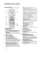
... Direct Access mode. [VCR operations] TV/VCR: Switches between TV/VCR. [CD Operations] DISC: Use to select function LD or DVD input signals. (i.e. O FUNCTION button Switches the function. § MULTI OPERATION button Use to set the multi operation. 03 POWER button Turns ON/OFF the power of the channel selected with the MULTI OPERATION but- The DSP mode does not function during while a Dolby Digital (AC-3) program source is selected or during ANALOG signal input. CH. SELECT button. C) LIST button Use to display the list screen when using the CD or tuner function. g MODE...
... Direct Access mode. [VCR operations] TV/VCR: Switches between TV/VCR. [CD Operations] DISC: Use to select function LD or DVD input signals. (i.e. O FUNCTION button Switches the function. § MULTI OPERATION button Use to set the multi operation. 03 POWER button Turns ON/OFF the power of the channel selected with the MULTI OPERATION but- The DSP mode does not function during while a Dolby Digital (AC-3) program source is selected or during ANALOG signal input. CH. SELECT button. C) LIST button Use to display the list screen when using the CD or tuner function. g MODE...
Service Manual
Page 84
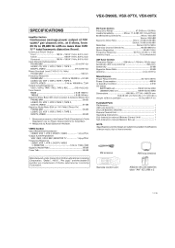
... dB (at 85 dBf) Stereo: 70 dB (at 6 ohms, from Dolby Laboratories Licensing Corporation. VSX-D906S, VSX-07TX, VSX-09TX SPECIFICATIONS Amplifier Section Continuous average power output of 100 watts* per channel, min., at 85 dBf) Distortion Stereo: 0.5 % (1kHz) Alternate Channel Selectivity 60 dB (400 kHz) Stereo Separation 40 dB (1 kHz) Frequency Response 30 Hz to 15 kHz (-±- 1) dB Antenna Input 75 0 unbalanced AM Tuner Section Frequency Range 530 kHz to 1,700...
... dB (at 85 dBf) Stereo: 70 dB (at 6 ohms, from Dolby Laboratories Licensing Corporation. VSX-D906S, VSX-07TX, VSX-09TX SPECIFICATIONS Amplifier Section Continuous average power output of 100 watts* per channel, min., at 85 dBf) Distortion Stereo: 0.5 % (1kHz) Alternate Channel Selectivity 60 dB (400 kHz) Stereo Separation 40 dB (1 kHz) Frequency Response 30 Hz to 15 kHz (-±- 1) dB Antenna Input 75 0 unbalanced AM Tuner Section Frequency Range 530 kHz to 1,700...


