Service Manual
Page 1
...-1760, U.S.A. Haven 1087, Keetberglaan 1, 9120 Melsele, Belgium PIONEER ELECTRONICS ASIACENTRE PTE. OD PIONEER® The Art of Entertainment Service Manual AUDIONIDEO STEREO RECEIVER VSX-D906S VSX-07TX VSX-09TX ORDER NO. PCB CONNECTION DIAGRAM 49 5. PANEL FACILITIES AND SPECIFICATIONS 108 PIONEER ELECTRONIC CORPORATION 4-1, Meguro 1-Chome, Meguro-ku, Tokyo 153, Japan PIONEER ELECTRONICS SERVICE, INC. LTD. 501 Orchard Road, #10...
...-1760, U.S.A. Haven 1087, Keetberglaan 1, 9120 Melsele, Belgium PIONEER ELECTRONICS ASIACENTRE PTE. OD PIONEER® The Art of Entertainment Service Manual AUDIONIDEO STEREO RECEIVER VSX-D906S VSX-07TX VSX-09TX ORDER NO. PCB CONNECTION DIAGRAM 49 5. PANEL FACILITIES AND SPECIFICATIONS 108 PIONEER ELECTRONIC CORPORATION 4-1, Meguro 1-Chome, Meguro-ku, Tokyo 153, Japan PIONEER ELECTRONICS SERVICE, INC. LTD. 501 Orchard Road, #10...
Service Manual
Page 58
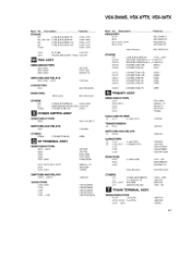
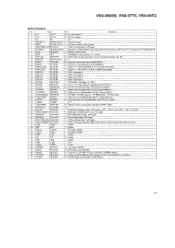
...IC102 (5A/125V) D101 -D104 51063 - 0405 AKP1053 RKR1003 VNF - 091 AEK7015 AEK7019 55688G 87 Description RESISTORS R204 R291 R271. VSX-D906S, VSX-07TX, VSX-09TX Mark No. R202 Parts No. C287 ASR 1035 CEAS222M25 CEAS470M50 CEAS472M I6 CEAS472M25 CKCYBIO2K2H Mark No. l µF/250V ) (10000pF... C281 - S838 V SCI008 CAPACITORS C83 I CKCYFIO3Z50 RESISTORS OTHERS 809 810 CN802 All Resistors RD1/4PUMEIJ CABLE HOLDER(4P) 51063-0405 REMOTE RECEIVER UNIT GPI U27X CONNECTOR(11P) KPE I A MTZJ5.6A S5688G COILS AND FILTERS A L121 (0 3mH/270V) ATF1006 TRANSFORMERS A T121 SWITCHES...
...IC102 (5A/125V) D101 -D104 51063 - 0405 AKP1053 RKR1003 VNF - 091 AEK7015 AEK7019 55688G 87 Description RESISTORS R204 R291 R271. VSX-D906S, VSX-07TX, VSX-09TX Mark No. R202 Parts No. C287 ASR 1035 CEAS222M25 CEAS470M50 CEAS472M I6 CEAS472M25 CKCYBIO2K2H Mark No. l µF/250V ) (10000pF... C281 - S838 V SCI008 CAPACITORS C83 I CKCYFIO3Z50 RESISTORS OTHERS 809 810 CN802 All Resistors RD1/4PUMEIJ CABLE HOLDER(4P) 51063-0405 REMOTE RECEIVER UNIT GPI U27X CONNECTOR(11P) KPE I A MTZJ5.6A S5688G COILS AND FILTERS A L121 (0 3mH/270V) ATF1006 TRANSFORMERS A T121 SWITCHES...
Service Manual
Page 67
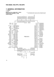
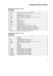
...s 5. ;I i_ .r.... _< j ,,, x iz0- ,i- in the schematic diagrams. • Block Diagram >w7- (7) O 0) co h cO u1-1- CO 0) CZ) .- 01 0 CO '0- 0) CO r- VSX-D906S, VSX-07TX, VSX-09TX 7. PE4/RMC PH3/A28 HPIN PE5 PH2/A29 FE_LED 1 1O EEPVCC -41 PE6/PWM PE7/TO/ADJ PH1/A30 PH0/A31 --700- zolzzzz < Z < < < < 2 I , > a0_...9632; PDG191A (FL-UCOM ASSY : IC801) • The information shown in the list is basic information and may • RECEIVER CONTROL µ-COM not correspond exactly to that shown in co r... IL co co r-- < CL a < < a< a< < > < o0 >c I- .xu., Et...
...s 5. ;I i_ .r.... _< j ,,, x iz0- ,i- in the schematic diagrams. • Block Diagram >w7- (7) O 0) co h cO u1-1- CO 0) CZ) .- 01 0 CO '0- 0) CO r- VSX-D906S, VSX-07TX, VSX-09TX 7. PE4/RMC PH3/A28 HPIN PE5 PH2/A29 FE_LED 1 1O EEPVCC -41 PE6/PWM PE7/TO/ADJ PH1/A30 PH0/A31 --700- zolzzzz < Z < < < < 2 I , > a0_...9632; PDG191A (FL-UCOM ASSY : IC801) • The information shown in the list is basic information and may • RECEIVER CONTROL µ-COM not correspond exactly to that shown in co r... IL co co r-- < CL a < < a< a< < > < o0 >c I- .xu., Et...
Service Manual
Page 68
... for extended IC BU4094 (1). 97 A/D input. 36 JOG 1/STEREO PA7/AN7 I JOG I : Port data input/TUNER: Stereo input (L: Receiving broadcasting in stereo). 37 GND AVSS GND. 38 RST RST I Fan temperature input. VSX-D906S, VSX-07TX, VSX-09TX • Pin Function No. Oscillator 8MHz. 40 XTAL XTAL Oscillator 8MHz. 41 GND VSS - GND. 42 TX...
... for extended IC BU4094 (1). 97 A/D input. 36 JOG 1/STEREO PA7/AN7 I JOG I : Port data input/TUNER: Stereo input (L: Receiving broadcasting in stereo). 37 GND AVSS GND. 38 RST RST I Fan temperature input. VSX-D906S, VSX-07TX, VSX-09TX • Pin Function No. Oscillator 8MHz. 40 XTAL XTAL Oscillator 8MHz. 41 GND VSS - GND. 42 TX...
Service Manual
Page 70
...LED lights up . LED lights up if LFE component is detected during decoding of M66311 (Set data to "L" when port output is TUNER. L . VSX-D906S, VSX-07TX, VSX-09TX • M66311FP (FL-UCOM ASSY : IC803) • LED DRIVER • Pin Function No. LED lights up when function is to be set... Vcc 4 DATA 5 OE 6 LATCH 7 RESET 8 CLOCK 9 GND 10 I ghts up . Reset input. Temporarily sets to "L" when the power switch is received. Clock line for communications with microcomputer. GND Fixed to "II". LED I ] 12 13 14 15 16 VCR1 IND. 17 VCR2 IND. 18 VIDEO IND. ...
...LED lights up . LED lights up if LFE component is detected during decoding of M66311 (Set data to "L" when port output is TUNER. L . VSX-D906S, VSX-07TX, VSX-09TX • M66311FP (FL-UCOM ASSY : IC803) • LED DRIVER • Pin Function No. LED lights up when function is to be set... Vcc 4 DATA 5 OE 6 LATCH 7 RESET 8 CLOCK 9 GND 10 I ghts up . Reset input. Temporarily sets to "L" when the power switch is received. Clock line for communications with microcomputer. GND Fixed to "II". LED I ] 12 13 14 15 16 VCR1 IND. 17 VCR2 IND. 18 VIDEO IND. ...
Service Manual
Page 79
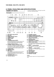
...Connect to raise the low and high frequency levels so that on the actual product. OPTICAL button SPEAKERS A, B buttons ON/OFF switches for receiving FM broadcasts. This button operates in stereo mode only. AM, FM buttons LIST IN button vii Select/Adjust buttons MASTER VOLUME *NOTE These ...set to a low level. (Works only when operating in the figure may differ from that the sound can be heard more easily. VSX-D906S, VSX-07TX, VSX-09TX 8. Front panel 1T T® OD PIONISF_11. BASS -, + buttons*NOTE Use to play back sound without going through the tone control circuits.
...Connect to raise the low and high frequency levels so that on the actual product. OPTICAL button SPEAKERS A, B buttons ON/OFF switches for receiving FM broadcasts. This button operates in stereo mode only. AM, FM buttons LIST IN button vii Select/Adjust buttons MASTER VOLUME *NOTE These ...set to a low level. (Works only when operating in the figure may differ from that the sound can be heard more easily. VSX-D906S, VSX-07TX, VSX-09TX 8. Front panel 1T T® OD PIONISF_11. BASS -, + buttons*NOTE Use to play back sound without going through the tone control circuits.
Service Manual
Page 80
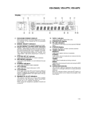
...cause electrical overload. When using headphones, the "H.P" indicator will light up whenever the analog input signal is ON. TUNED: Lights when broadcasts are turned off. VSX-D906S, VSX-07TX, VSX-09TX Display O CD © PROGRAM FC RMAT DISPLAY L C R O O O LS S Rs O O O LFE CD SIGNAL SELECT AC-3 ...indicator blinks, press the ATT button on and indicates the type selected. When using the headphone, speakers A and B are being received. The LFE indicator also lights when LFE signals are two Dolby Surround modes-Dolby Digital (AC-3) and Dolby Pro Logic. O TAPE...
...cause electrical overload. When using headphones, the "H.P" indicator will light up whenever the analog input signal is ON. TUNED: Lights when broadcasts are turned off. VSX-D906S, VSX-07TX, VSX-09TX Display O CD © PROGRAM FC RMAT DISPLAY L C R O O O LS S Rs O O O LFE CD SIGNAL SELECT AC-3 ...indicator blinks, press the ATT button on and indicates the type selected. When using the headphone, speakers A and B are being received. The LFE indicator also lights when LFE signals are two Dolby Surround modes-Dolby Digital (AC-3) and Dolby Pro Logic. O TAPE...
Service Manual
Page 83
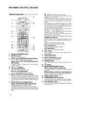
... button Use to turn OFF the power of other than RECEIVER (OP- g MODE CHECK button ® COMMANDER SET UP button Use to control and learn operations of all equipment connected to the main unit. 1 12 VSX-D906S, VSX-07TX, VSX-09TX Remote control unit RECEIVPEORNR/I FUNCTION Li" "" vn,... LIST MODE CIEEE MULTI COMSETMUP'S OPERATION SYSTEM OFF SEi UP PIONEEll 931 CI RECEIVER POWER button ® MUTING button Press to mute the volume....
... button Use to turn OFF the power of other than RECEIVER (OP- g MODE CHECK button ® COMMANDER SET UP button Use to control and learn operations of all equipment connected to the main unit. 1 12 VSX-D906S, VSX-07TX, VSX-09TX Remote control unit RECEIVPEORNR/I FUNCTION Li" "" vn,... LIST MODE CIEEE MULTI COMSETMUP'S OPERATION SYSTEM OFF SEi UP PIONEEll 931 CI RECEIVER POWER button ® MUTING button Press to mute the volume....


