Service Manual
Page 1
.... 501 Orchard Road, #10-00 Lane Crawford Place, Singapore 0923 © PIONEER ELECTRONIC CORPORATION 1997 T-FZK MAY 1997 Printed in Belgium OD PIONEER® The Art of Entertainment Service Manual AUDIONIDEO STEREO RECEIVER VSX-D906S VSX-07TX VSX-09TX ORDER NO. KU O AC120V KC O AC120V SD O - SCHEMATIC DIAGRAM 12 4. PCB CONNECTION DIAGRAM 49 5. ADJUSTMENT 93 7. PANEL FACILITIES...
.... 501 Orchard Road, #10-00 Lane Crawford Place, Singapore 0923 © PIONEER ELECTRONIC CORPORATION 1997 T-FZK MAY 1997 Printed in Belgium OD PIONEER® The Art of Entertainment Service Manual AUDIONIDEO STEREO RECEIVER VSX-D906S VSX-07TX VSX-09TX ORDER NO. KU O AC120V KC O AC120V SD O - SCHEMATIC DIAGRAM 12 4. PCB CONNECTION DIAGRAM 49 5. ADJUSTMENT 93 7. PANEL FACILITIES...
Service Manual
Page 2
...circuit boards and other reproductive harm (California Health & Safety Code, Section 25249.5). Electrical components having such features are issued from PIONEER. 2 Device under review and new instructions are identified by using replacement components rated for the casual do not inhale any ... SHOCK HAZARD AND MUST BE CORRECTED BEFORE RETURNING THE APPLIANCE TO THE CUSTOMER. 2. on the schematics and on the parts list in this Service Manual, may cause birth defects or other components which have special safety related characteristics. VSX-D906S, VSX-07TX, VSX-09TX 1.
...circuit boards and other reproductive harm (California Health & Safety Code, Section 25249.5). Electrical components having such features are issued from PIONEER. 2 Device under review and new instructions are identified by using replacement components rated for the casual do not inhale any ... SHOCK HAZARD AND MUST BE CORRECTED BEFORE RETURNING THE APPLIANCE TO THE CUSTOMER. 2. on the schematics and on the parts list in this Service Manual, may cause birth defects or other components which have special safety related characteristics. VSX-D906S, VSX-07TX, VSX-09TX 1.
Service Manual
Page 12
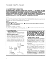
... DOLBY DIGITAL ASSY 12 FAN 0167012 J11 ," J35 -' 21 4141 { 215009 , ( 015410),, ,„ .52 i 7, 150 i , 909 , iip I 6-1007 (/) CONNECTION ASSY C,657 0T 4 19 1,42 2 OTA 9 t t (' J 0 ..', ,,-. SCHEMATIC DIAGRAM Note : When ordering service parts, be sure to refer to "EXPLODED VIEWS and PARTS LIST" or "PCB PARTS LIST" 3.1 OVERALL CONNECTION DIAGRAM JI7 )15009... 05 I-3- 10-5"54-70995 ' 2j" 09, KEY ASSY wi 51053-0005 FL-UCOM ASSY I D15A09 750 ) li!2)RMC ASSY ,-4405 ( 215A11 , 221 2'5404 200 9,18. VSX-D906S, VSX-07TX, VSX-09TX 3.
... DOLBY DIGITAL ASSY 12 FAN 0167012 J11 ," J35 -' 21 4141 { 215009 , ( 015410),, ,„ .52 i 7, 150 i , 909 , iip I 6-1007 (/) CONNECTION ASSY C,657 0T 4 19 1,42 2 OTA 9 t t (' J 0 ..', ,,-. SCHEMATIC DIAGRAM Note : When ordering service parts, be sure to refer to "EXPLODED VIEWS and PARTS LIST" or "PCB PARTS LIST" 3.1 OVERALL CONNECTION DIAGRAM JI7 )15009... 05 I-3- 10-5"54-70995 ' 2j" 09, KEY ASSY wi 51053-0005 FL-UCOM ASSY I D15A09 750 ) li!2)RMC ASSY ,-4405 ( 215A11 , 221 2'5404 200 9,18. VSX-D906S, VSX-07TX, VSX-09TX 3.
Service Manual
Page 49
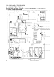
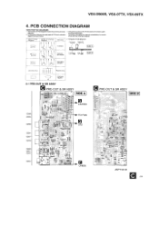
... parts of PCB diagrams Connector / Capacitor SIDE A st' p-t' BC E D G S B C E8 C E Y._ I ( ,-1. ) 143) ''--7-DG SO G S L. Part numbers in PCB diagrams match those in Schematic Diagrams B C EB Ct 0 C, ii ,,-- -1. Symbol in PCB Diagrams S. 0 0 B C E Symbol in the schematic diagrams. 2. L Transistor with the schematic diagram. VSX-D906S, VSX-07TX, VSX-09TX 4. CE 0 (-_, -3,, part Name Transistor 4. PCB CONNECTION DIAGRAM NOTE FOR PCB DIAGRAMS 1.
... parts of PCB diagrams Connector / Capacitor SIDE A st' p-t' BC E D G S B C E8 C E Y._ I ( ,-1. ) 143) ''--7-DG SO G S L. Part numbers in PCB diagrams match those in Schematic Diagrams B C EB Ct 0 C, ii ,,-- -1. Symbol in PCB Diagrams S. 0 0 B C E Symbol in the schematic diagrams. 2. L Transistor with the schematic diagram. VSX-D906S, VSX-07TX, VSX-09TX 4. CE 0 (-_, -3,, part Name Transistor 4. PCB CONNECTION DIAGRAM NOTE FOR PCB DIAGRAMS 1.
Service Manual
Page 67
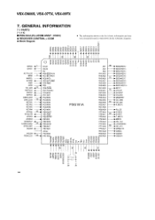
... information shown in the list is basic information and may • RECEIVER CONTROL µ-COM not correspond exactly to that shown in co r... in the schematic diagrams. • Block Diagram >w7- (7) O 0) co h cO u1-1- co co r-- < CL a < < a< a< < > < o0 >c I- .xu., Et EL X > I , > a0_ 0_ co CL CL aci 0 SEG9/KEY2 ► SEG8.../SC1 PF2/A45 PF1/A46 55 AC3CE PB7/SO1 PF0/A47 AVREF PD7/A48 VOLDN -4 PA0/AN0 PD6/A49 PEAK.LEV 30 • PA1/AN1N . VSX-D906S, VSX-07TX, VSX-09TX 7. IL
... information shown in the list is basic information and may • RECEIVER CONTROL µ-COM not correspond exactly to that shown in co r... in the schematic diagrams. • Block Diagram >w7- (7) O 0) co h cO u1-1- co co r-- < CL a < < a< a< < > < o0 >c I- .xu., Et EL X > I , > a0_ 0_ co CL CL aci 0 SEG9/KEY2 ► SEG8.../SC1 PF2/A45 PF1/A46 55 AC3CE PB7/SO1 PF0/A47 AVREF PD7/A48 VOLDN -4 PA0/AN0 PD6/A49 PEAK.LEV 30 • PA1/AN1N . VSX-D906S, VSX-07TX, VSX-09TX 7. IL
