Owner's Manual
Page 6
... 81 Checking your system settings 81 Resetting the system 82 Default system settings 82 10 Controlling the rest of your system (In case of SC-37) About the Remote Setup menu 83 Operating multiple receivers 84 Setting the remote to control other components . . . . 84 Selecting preset ... assignment of one of the input function buttons 86 Resetting the remote control settings 86 Confirming preset codes 86 Renaming input function names manually 86 Direct function 86 Multi Operation and System Off 87 Programming a multi-operation or a shutdown sequence 87 Using multi operations 88 ...
... 81 Checking your system settings 81 Resetting the system 82 Default system settings 82 10 Controlling the rest of your system (In case of SC-37) About the Remote Setup menu 83 Operating multiple receivers 84 Setting the remote to control other components . . . . 84 Selecting preset ... assignment of one of the input function buttons 86 Resetting the remote control settings 86 Confirming preset codes 86 Renaming input function names manually 86 Direct function 86 Multi Operation and System Off 87 Programming a multi-operation or a shutdown sequence 87 Using multi operations 88 ...
Owner's Manual
Page 7
...Flicker Reduction Setup 120 RF Remote Setup (SC-37 only 120 EXTENSION Setup (SC-35 only 120 Multi Channel Input Setup 120 11 The Advanced MCACC menu Making receiver settings from the Advanced MCACC menu 104 Automatic MCACC (Expert 104 Manual MCACC setup 106 Fine Channel Level 107... Fine Speaker Distance 107 Standing Wave 107 Acoustic Calibration EQ Adjust 108 Acoustic Calibration EQ Professional 108 Precision Distance (SC-37 only 110 Checking MCACC Data 110 Speaker Setting 111...
...Flicker Reduction Setup 120 RF Remote Setup (SC-37 only 120 EXTENSION Setup (SC-35 only 120 Multi Channel Input Setup 120 11 The Advanced MCACC menu Making receiver settings from the Advanced MCACC menu 104 Automatic MCACC (Expert 104 Manual MCACC setup 106 Fine Channel Level 107... Fine Speaker Distance 107 Standing Wave 107 Acoustic Calibration EQ Adjust 108 Acoustic Calibration EQ Professional 108 Precision Distance (SC-37 only 110 Checking MCACC Data 110 Speaker Setting 111...
Owner's Manual
Page 20
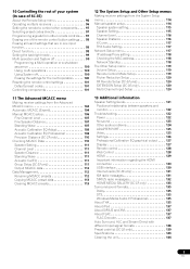
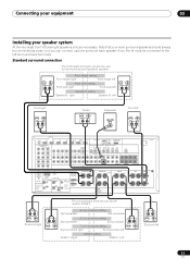
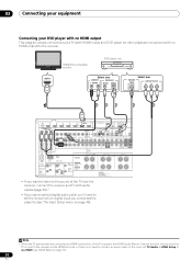
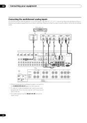
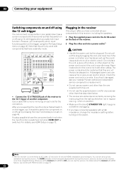
... 75 CONTROL IN IN 1 IR IN 2 OUT OUT 12 V 1 TRIGGER (OUTPUT 12 V 2 TOTAL 150 mA MAX) SELECTABLE SEE INSTRUCTION MANUAL SELECTABLE VOIR LE MODE D'EMPLOI CAUTION: SPEAKER IMPEDANCE 6 Ω - 16 Ω . Rear panel SC-37 HDMI BD IN IN 1 IN 2 IN 3 IN 4 OUT 1 (CONTROL) OUT 2 LAN (10/100) ASSIGNABLE 14 XM ADAPTER PORT... make up your equipment This receiver provides you can connect to be difficult. ATTENTION: ENCEINTE D'IMPEDANCE DE 6 Ω - 16 Ω . Important • Illustration shows the SC-37, however connections for the SC-35 are the same except where noted.
... 75 CONTROL IN IN 1 IR IN 2 OUT OUT 12 V 1 TRIGGER (OUTPUT 12 V 2 TOTAL 150 mA MAX) SELECTABLE SEE INSTRUCTION MANUAL SELECTABLE VOIR LE MODE D'EMPLOI CAUTION: SPEAKER IMPEDANCE 6 Ω - 16 Ω . Rear panel SC-37 HDMI BD IN IN 1 IN 2 IN 3 IN 4 OUT 1 (CONTROL) OUT 2 LAN (10/100) ASSIGNABLE 14 XM ADAPTER PORT... make up your equipment This receiver provides you can connect to be difficult. ATTENTION: ENCEINTE D'IMPEDANCE DE 6 Ω - 16 Ω . Important • Illustration shows the SC-37, however connections for the SC-35 are the same except where noted.
Owner's Manual
Page 24
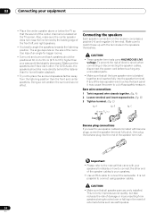
... cables. Important • Please refer to connect the subwoofer. Use less of the speaker cables to your speakers. • Use an RCA cable to the manual that all speakers are securely installed. Bare wire connections 1 Twist exposed wire strands together. (fig. Make sure the speakers don't face each other end of...
... cables. Important • Please refer to connect the subwoofer. Use less of the speaker cables to your speakers. • Use an RCA cable to the manual that all speakers are securely installed. Bare wire connections 1 Twist exposed wire strands together. (fig. Make sure the speakers don't face each other end of...
Owner's Manual
Page 25
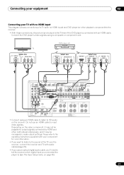
...) CU-RF100 AM LOOP FM UNBAL 75 CONTROL IN IN 1 IR IN 2 OUT OUT 12 V 1 TRIGGER (OUTPUT 12 V 2 TOTAL 150 mA MAX) SELECTABLE SEE INSTRUCTION MANUAL SELECTABLE VOIR LE MODE D'EMPLOI CAUTION: SPEAKER IMPEDANCE 6 Ω - 16 Ω .
...) CU-RF100 AM LOOP FM UNBAL 75 CONTROL IN IN 1 IR IN 2 OUT OUT 12 V 1 TRIGGER (OUTPUT 12 V 2 TOTAL 150 mA MAX) SELECTABLE SEE INSTRUCTION MANUAL SELECTABLE VOIR LE MODE D'EMPLOI CAUTION: SPEAKER IMPEDANCE 6 Ω - 16 Ω .
Owner's Manual
Page 26
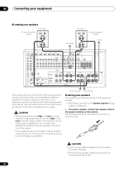
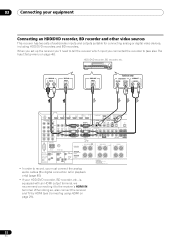
...AM LOOP FM UNBAL 75 CONTROL IN IN 1 IR IN 2 OUT OUT 12 V 1 TRIGGER (OUTPUT 12 V 2 TOTAL 150 mA MAX) SELECTABLE SEE INSTRUCTION MANUAL SELECTABLE VOIR LE MODE D'EMPLOI CAUTION: SPEAKER IMPEDANCE 6 Ω - 16 Ω . CAUTION • Don't connect different speakers from the same terminal in ... damage the amplifier. FRONT R CENTER L AC IN A Bi-amping is recommended. Surround right Surround left . 26 En See your speaker manual for more information. • If your speakers to the speaker terminal on the kind of your speakers have two metal plates that connect the...
...AM LOOP FM UNBAL 75 CONTROL IN IN 1 IR IN 2 OUT OUT 12 V 1 TRIGGER (OUTPUT 12 V 2 TOTAL 150 mA MAX) SELECTABLE SEE INSTRUCTION MANUAL SELECTABLE VOIR LE MODE D'EMPLOI CAUTION: SPEAKER IMPEDANCE 6 Ω - 16 Ω . CAUTION • Don't connect different speakers from the same terminal in ... damage the amplifier. FRONT R CENTER L AC IN A Bi-amping is recommended. Surround right Surround left . 26 En See your speaker manual for more information. • If your speakers to the speaker terminal on the kind of your speakers have two metal plates that connect the...
Owner's Manual
Page 29
... 2 Wiring SIGNAL GND FRONT HEIGHT/WIDE/ B R L SUBWOOFER PRE OUT SUBW SURROUND BACK SURROUND R L (Single) R L 12 V 1 TRIGGER (OUTPUT 12 V 2 TOTAL 150 mA MAX) SELECTABLE SEE INSTRUCTION MANUAL SELECTABLE VOIR LE MODE D'EMPLOI CAUTION: SPEAKER IMPEDANCE 6 Ω - 16 Ω . ATTENTION: ENCEINTE D'IMPEDANCE DE 6 Ω - 16 Ω . • When connecting to an HDMI/DVI...
... 2 Wiring SIGNAL GND FRONT HEIGHT/WIDE/ B R L SUBWOOFER PRE OUT SUBW SURROUND BACK SURROUND R L (Single) R L 12 V 1 TRIGGER (OUTPUT 12 V 2 TOTAL 150 mA MAX) SELECTABLE SEE INSTRUCTION MANUAL SELECTABLE VOIR LE MODE D'EMPLOI CAUTION: SPEAKER IMPEDANCE 6 Ω - 16 Ω . ATTENTION: ENCEINTE D'IMPEDANCE DE 6 Ω - 16 Ω . • When connecting to an HDMI/DVI...
Owner's Manual
Page 30
... 2 Wiring SIGNAL GND FRONT HEIGHT/WIDE/ B R L SUBWOOFER PRE OUT SUBWOOFER SURROUND BACK SURROUND R L (Single) R L 12 V 1 TRIGGER (OUTPUT 12 V 2 TOTAL 150 mA MAX) SELECTABLE SEE INSTRUCTION MANUAL SELECTABLE VOIR LE MODE D'EMPLOI CAUTION: SPEAKER IMPEDANCE 6 Ω - 16 Ω . 03 Connecting your equipment Connecting your DVD player with no HDMI output This diagram...
... 2 Wiring SIGNAL GND FRONT HEIGHT/WIDE/ B R L SUBWOOFER PRE OUT SUBWOOFER SURROUND BACK SURROUND R L (Single) R L 12 V 1 TRIGGER (OUTPUT 12 V 2 TOTAL 150 mA MAX) SELECTABLE SEE INSTRUCTION MANUAL SELECTABLE VOIR LE MODE D'EMPLOI CAUTION: SPEAKER IMPEDANCE 6 Ω - 16 Ω . 03 Connecting your equipment Connecting your DVD player with no HDMI output This diagram...
Owner's Manual
Page 31
... 2 Wiring SIGNAL GND FRONT HEIGHT/WIDE/ B R L SUBWOOFER PRE OUT SUBWOOFER SURROUND BACK SURROUND R L (Single) R L 12 V 1 TRIGGER (OUTPUT 12 V 2 TOTAL 150 mA MAX) SELECTABLE SEE INSTRUCTION MANUAL SELECTABLE VOIR LE MODE D'EMPLOI CAUTION: SPEAKER IMPEDANCE 6 Ω - 16 Ω .
... 2 Wiring SIGNAL GND FRONT HEIGHT/WIDE/ B R L SUBWOOFER PRE OUT SUBWOOFER SURROUND BACK SURROUND R L (Single) R L 12 V 1 TRIGGER (OUTPUT 12 V 2 TOTAL 150 mA MAX) SELECTABLE SEE INSTRUCTION MANUAL SELECTABLE VOIR LE MODE D'EMPLOI CAUTION: SPEAKER IMPEDANCE 6 Ω - 16 Ω .
Owner's Manual
Page 32
... 2 Wiring SIGNAL GND FRONT HEIGHT/WIDE/ B R L SUBWOOFER PRE OUT SUBWOOFER SURROUND BACK SURROUND R L (Single) R L 12 V 1 TRIGGER (OUTPUT 12 V 2 TOTAL 150 mA MAX) SELECTABLE SEE INSTRUCTION MANUAL SELECTABLE VOIR LE MODE D'EMPLOI CAUTION: SPEAKER IMPEDANCE 6 Ω - 16 Ω . ATTENTION: ENCEINTE D'IMPEDANCE DE 6 Ω - 16 Ω . • In order to record, you connected...
... 2 Wiring SIGNAL GND FRONT HEIGHT/WIDE/ B R L SUBWOOFER PRE OUT SUBWOOFER SURROUND BACK SURROUND R L (Single) R L 12 V 1 TRIGGER (OUTPUT 12 V 2 TOTAL 150 mA MAX) SELECTABLE SEE INSTRUCTION MANUAL SELECTABLE VOIR LE MODE D'EMPLOI CAUTION: SPEAKER IMPEDANCE 6 Ω - 16 Ω . ATTENTION: ENCEINTE D'IMPEDANCE DE 6 Ω - 16 Ω . • In order to record, you connected...
Owner's Manual
Page 33
... 2 Wiring SIGNAL GND FRONT HEIGHT/WIDE/ B R L SUBWOOFER PRE OUT SUBWOOFER SURROUND BACK SURROUND R L (Single) R L 12 V 1 TRIGGER (OUTPUT 12 V 2 TOTAL 150 mA MAX) SELECTABLE SEE INSTRUCTION MANUAL SELECTABLE VOIR LE MODE D'EMPLOI CAUTION: SPEAKER IMPEDANCE 6 Ω - 16 Ω .
... 2 Wiring SIGNAL GND FRONT HEIGHT/WIDE/ B R L SUBWOOFER PRE OUT SUBWOOFER SURROUND BACK SURROUND R L (Single) R L 12 V 1 TRIGGER (OUTPUT 12 V 2 TOTAL 150 mA MAX) SELECTABLE SEE INSTRUCTION MANUAL SELECTABLE VOIR LE MODE D'EMPLOI CAUTION: SPEAKER IMPEDANCE 6 Ω - 16 Ω .
Owner's Manual
Page 34
.../WIDE/ B R L SUBWOOFER PRE OUT SUBWOOFER R MULTI CH IN SURROUND BACK SURROUND R L (Single) R L FRONT R CENTER L 12 V 1 TRIGGER (OUTPUT 12 V 2 TOTAL 150 mA MAX) SELECTABLE SEE INSTRUCTION MANUAL SELECTABLE VOIR LE MODE D'EMPLOI CAUTION: SPEAKER IMPEDANCE 6 Ω - 16 Ω . Make sure that the player is a single surround back output, connect it to the...
.../WIDE/ B R L SUBWOOFER PRE OUT SUBWOOFER R MULTI CH IN SURROUND BACK SURROUND R L (Single) R L FRONT R CENTER L 12 V 1 TRIGGER (OUTPUT 12 V 2 TOTAL 150 mA MAX) SELECTABLE SEE INSTRUCTION MANUAL SELECTABLE VOIR LE MODE D'EMPLOI CAUTION: SPEAKER IMPEDANCE 6 Ω - 16 Ω . Make sure that the player is a single surround back output, connect it to the...
Owner's Manual
Page 35
... 2 Wiring SIGNAL GND FRONT HEIGHT/WIDE/ B R L SUBWOOFER PRE OUT SUBWOOFER SURROUND BACK SURROUND R L (Single) R L R 12 V 1 TRIGGER (OUTPUT 12 V 2 TOTAL 150 mA MAX) SELECTABLE SEE INSTRUCTION MANUAL SELECTABLE VOIR LE MODE D'EMPLOI CAUTION: SPEAKER IMPEDANCE 6 Ω - 16 Ω . Note that WMA9 Pro 96 kHz sources will be able to output WMA9 Pro...
... 2 Wiring SIGNAL GND FRONT HEIGHT/WIDE/ B R L SUBWOOFER PRE OUT SUBWOOFER SURROUND BACK SURROUND R L (Single) R L R 12 V 1 TRIGGER (OUTPUT 12 V 2 TOTAL 150 mA MAX) SELECTABLE SEE INSTRUCTION MANUAL SELECTABLE VOIR LE MODE D'EMPLOI CAUTION: SPEAKER IMPEDANCE 6 Ω - 16 Ω . Note that WMA9 Pro 96 kHz sources will be able to output WMA9 Pro...
Owner's Manual
Page 38
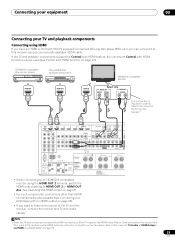
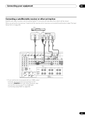
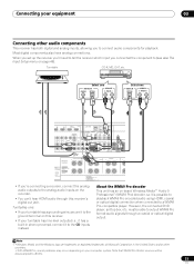
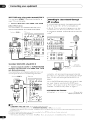
..., it is connected. • The video convert function does not work for the inputs and outputs. 2 To listen to set up the network manually. Connect the composite video and component video to the same types of jacks for ZONE 2. You should have a pair of speakers attached to the ... Connecting to the network through LAN interface By connecting this receiver to the network via the LAN terminal, you can listen to Internet radio stations.2 SC-37 only: When connected in this way, you can even play audio files stored on the components on the network, including your computer, using speaker...
..., it is connected. • The video convert function does not work for the inputs and outputs. 2 To listen to set up the network manually. Connect the composite video and component video to the same types of jacks for ZONE 2. You should have a pair of speakers attached to the ... Connecting to the network through LAN interface By connecting this receiver to the network via the LAN terminal, you can listen to Internet radio stations.2 SC-37 only: When connected in this way, you can even play audio files stored on the components on the network, including your computer, using speaker...
Owner's Manual
Page 41
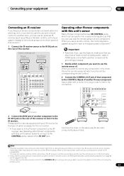
... FM UNBAL 75 CONTROL IN IN 1 IR IN 2 OUT OUT SPEAKERS Class 2 Wiring 12 V 1 TRIGGER (OUTPUT 12 V 2 TOTAL 150 mA MAX) SELECTABLE SEE INSTRUCTIO MANUAL SELECTABLE VOIR LE MODE D'EMPLOI IR receiver 2 Connect the IR IN jack of another component to the IR OUT jack on the rear of this...takes priority over the remote sensor on the front panel. 2 • If you want to link a Pioneer component to the IR receiver, see Setting the remote to control other components on page 84 (SC-37)/page 97 (SC-35). • If you have . Connecting your equipment 03 Connecting an IR receiver If you keep...
... FM UNBAL 75 CONTROL IN IN 1 IR IN 2 OUT OUT SPEAKERS Class 2 Wiring 12 V 1 TRIGGER (OUTPUT 12 V 2 TOTAL 150 mA MAX) SELECTABLE SEE INSTRUCTIO MANUAL SELECTABLE VOIR LE MODE D'EMPLOI IR receiver 2 Connect the IR IN jack of another component to the IR OUT jack on the rear of this...takes priority over the remote sensor on the front panel. 2 • If you want to link a Pioneer component to the IR receiver, see Setting the remote to control other components on page 84 (SC-37)/page 97 (SC-35). • If you have . Connecting your equipment 03 Connecting an IR receiver If you keep...
Owner's Manual
Page 42
... have a standby mode. A damaged power cord can cause a fire or give you can turn on this receiver once it damaged, ask your nearest Pioneer authorized independent service company for a replacement. • Do not use , e.g., when on vacation. • Make sure the blue STANDBY/... 2 OUT OUT SPEAKERS Class 2 Wiring SIGNAL GND FRONT HEIGHT/W R 12 V 1 TRIGGER (OUTPUT 12 V 2 TOTAL 150 mA MAX) SELECTABLE SEE INSTRUCTION MANUAL SELECTABLE VOIR LE MODE D'EMPLOI 12 V TRIGGER INPUT • Connect the 12 V TRIGGER jack of this could cause a short circuit or electric shock. Plugging...
... have a standby mode. A damaged power cord can cause a fire or give you can turn on this receiver once it damaged, ask your nearest Pioneer authorized independent service company for a replacement. • Do not use , e.g., when on vacation. • Make sure the blue STANDBY/... 2 OUT OUT SPEAKERS Class 2 Wiring SIGNAL GND FRONT HEIGHT/W R 12 V 1 TRIGGER (OUTPUT 12 V 2 TOTAL 150 mA MAX) SELECTABLE SEE INSTRUCTION MANUAL SELECTABLE VOIR LE MODE D'EMPLOI 12 V TRIGGER INPUT • Connect the 12 V TRIGGER jack of this could cause a short circuit or electric shock. Plugging...
Owner's Manual
Page 44
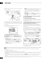
... will be as quiet as Too much ambient noise! Select the proper speaker system, then press RETURN to SMALL), otherwise leave it later in the Manual MCACC setup (page 106). 4 If you leave the GUI screen for now (you have a tripod, use it 's about ear level at your setup. If no...
... will be as quiet as Too much ambient noise! Select the proper speaker system, then press RETURN to SMALL), otherwise leave it later in the Manual MCACC setup (page 106). 4 If you leave the GUI screen for now (you have a tripod, use it 's about ear level at your setup. If no...
Owner's Manual
Page 45
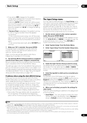
... the optimum receiver settings. A progress report is displayed on the back of the speakers and viewing environment, we recommend adjusting the settings manually. 45 En If selecting RETRY doesn't work, turn off the TV when doing the Auto MCACC Setup. If there doesn't seem to... to navigate through the screens and select menu items. Press RETURN to disconnect the microphone from the System Setup menu. 4.System Setup A/V RECEIVER a.Manual SP Setup b. Input Setup c. There are properly connected. 2 • Depending on page 114. • The subwoofer distance setting may be...
... the optimum receiver settings. A progress report is displayed on the back of the speakers and viewing environment, we recommend adjusting the settings manually. 45 En If selecting RETRY doesn't work, turn off the TV when doing the Auto MCACC Setup. If there doesn't seem to... to navigate through the screens and select menu items. Press RETURN to disconnect the microphone from the System Setup menu. 4.System Setup A/V RECEIVER a.Manual SP Setup b. Input Setup c. There are properly connected. 2 • Depending on page 114. • The subwoofer distance setting may be...
Owner's Manual
Page 47
... of the subwoofer can be set your DVD player or digital satellite receiver. For details, see Auto Surround, ALC and Stream Direct with the SC-37 and SC-35. It is possible to your system components and receiver. In this case, the output level of your component or display. Playing a source... playing a source (such as above . Note that may need to check the digital audio output settings on the DVD player you might need to manually switch the input signal type press SIGNAL SEL (page 62). 2 You may not be heard from the front left/right speakers in Other Setup....
... of the subwoofer can be set your DVD player or digital satellite receiver. For details, see Auto Surround, ALC and Stream Direct with the SC-37 and SC-35. It is possible to your system components and receiver. In this case, the output level of your component or display. Playing a source... playing a source (such as above . Note that may need to check the digital audio output settings on the DVD player you might need to manually switch the input signal type press SIGNAL SEL (page 62). 2 You may not be heard from the front left/right speakers in Other Setup....
Owner's Manual
Page 52
... a station you want , see Saving station presets below . Press and hold TUNE / for about a second. Tuning directly to a station 1 SC-37 only: Set the remote control operation selector switch to SOURCE. 2 Press TUNER to select the tuner. 3 Use BAND to change the frequency one step at... FM radio, press AUTO/ALC/ DIRECT for recall later-see Tuning directly to FM and AM radio broadcasts using the automatic (search) and manual (step) tuning functions. If you already know the frequency of the radio station. Repeat to recall the station preset. 52 En High speed...
... a station you want , see Saving station presets below . Press and hold TUNE / for about a second. Tuning directly to a station 1 SC-37 only: Set the remote control operation selector switch to SOURCE. 2 Press TUNER to select the tuner. 3 Use BAND to change the frequency one step at... FM radio, press AUTO/ALC/ DIRECT for recall later-see Tuning directly to FM and AM radio broadcasts using the automatic (search) and manual (step) tuning functions. If you already know the frequency of the radio station. Repeat to recall the station preset. 52 En High speed...


