Owner's Manual
Page 3
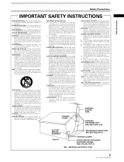
... antenna discharge unit, size of grounding conductors, location of the product should follow the manufacturer's instructions, and should be operated only from the type of other controls may fall into the outlet, try reversing the plug. Adjust only those controls that are unable to the product. REPLACEMENT PARTS - Do not use a mounting accessory recommended by the product manufacturer as an improper adjustment of power source...
... antenna discharge unit, size of grounding conductors, location of the product should follow the manufacturer's instructions, and should be operated only from the type of other controls may fall into the outlet, try reversing the plug. Adjust only those controls that are unable to the product. REPLACEMENT PARTS - Do not use a mounting accessory recommended by the product manufacturer as an improper adjustment of power source...
Owner's Manual
Page 5
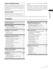
... Automatic Power OFF 24 Display Panel Adjustments 25 Adjusting the Picture Quality 25 Adjusting the Image Position and Clock (Automatic Adjustment 26 Manual Adjustment of Screen Position and Clock 26 Other Operations 28 Rewriting the Input Display (INPUT LABEL) ........ 28 Changing the Color Temperature (COLOR TEMP 29 Reducing Video Noise (DIGITAL NR 29 Setting the PureCinema mode 30 Viewing a Fast Moving Picture (3D Y/C MODE 30 Viewing in a Bright Location (HIGH CONTRAST 31 Power Control Function 31 AUTO FUNCTION 32 Audio Output (AUDIO OUT...
... Automatic Power OFF 24 Display Panel Adjustments 25 Adjusting the Picture Quality 25 Adjusting the Image Position and Clock (Automatic Adjustment 26 Manual Adjustment of Screen Position and Clock 26 Other Operations 28 Rewriting the Input Display (INPUT LABEL) ........ 28 Changing the Color Temperature (COLOR TEMP 29 Reducing Video Noise (DIGITAL NR 29 Setting the PureCinema mode 30 Viewing a Fast Moving Picture (3D Y/C MODE 30 Viewing in a Bright Location (HIGH CONTRAST 31 Power Control Function 31 AUTO FUNCTION 32 Audio Output (AUDIO OUT...
Owner's Manual
Page 6
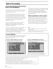
... section "Installation and Connections" starting on page 8 covers all the parts have been received, it has been confirmed that would seem most logical for the PRO-1000HD model. Screen Displays The example screen displays provided in both the PRO-1000HD and PRO-800HD. E NHANCE V. Most of the box, and it may vary depending on -screen menu settings to the more complex operations associated with the plasma monitor and remote control unit...
... section "Installation and Connections" starting on page 8 covers all the parts have been received, it has been confirmed that would seem most logical for the PRO-1000HD model. Screen Displays The example screen displays provided in both the PRO-1000HD and PRO-800HD. E NHANCE V. Most of the box, and it may vary depending on -screen menu settings to the more complex operations associated with the plasma monitor and remote control unit...
Owner's Manual
Page 15
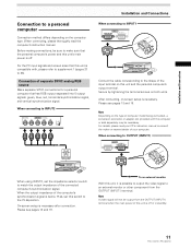
... tightening the terminal screws on the computer type. After connecting, on-screen setup is necessary after connection. On-screen setup is necessary. To an external monitor With this unit, it is possible to output the video signal to an external monitor or other component from the OUTPUT (INPUT1) terminal when the main power of the computer's synchronization signal is off or in standby. 11 PRO-1000HD / PRO-800HD Note Depending on...
... tightening the terminal screws on the computer type. After connecting, on-screen setup is necessary after connection. On-screen setup is necessary. To an external monitor With this unit, it is possible to output the video signal to an external monitor or other component from the OUTPUT (INPUT1) terminal when the main power of the computer's synchronization signal is off or in standby. 11 PRO-1000HD / PRO-800HD Note Depending on...
Owner's Manual
Page 23
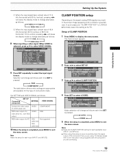
.... Connected component SET UP SETTING VIDEO SIGNAL Component video output VIDEO of a DVD player, etc. L EVEL G. L EVEL H. MAIN MENU INPUT1 PICTURE SCREEN SET UP OPTION I NPUT L ABEL : I NPUT 1 POWE R MA NAGEME NT : OF F CL AMP P OS I T I ON : L OCK E D SETT I NG : VGA Mode selection will change as follows each applicable input (INPUT1 and INPUT2). ÷ When using . Notes ÷ Make this CLAMP POSITION setting for each time SET is pressed. 3 AUTO LOCKED 2 5 When the setup...
.... Connected component SET UP SETTING VIDEO SIGNAL Component video output VIDEO of a DVD player, etc. L EVEL G. L EVEL H. MAIN MENU INPUT1 PICTURE SCREEN SET UP OPTION I NPUT L ABEL : I NPUT 1 POWE R MA NAGEME NT : OF F CL AMP P OS I T I ON : L OCK E D SETT I NG : VGA Mode selection will change as follows each applicable input (INPUT1 and INPUT2). ÷ When using . Notes ÷ Make this CLAMP POSITION setting for each time SET is pressed. 3 AUTO LOCKED 2 5 When the setup...

Owner's Manual
Page 28
... automatic powermanagement and auto-power-off the plasma display's main power switch when not using the display for extended periods of time. 1 Press MENU to display the menu screen. MAIN MENU PICTURE SCREEN CONT RAST BR I NG : VGA 4 Press SET to confirm selection of the POWER MANAGEMENT or AUTO POWER OFF. 3 OFF ON 2 ÷ When OFF is selected, the display will switch to STANDBY mode. 5 When the setup is input to INPUT 1. ÷ The auto-power-off function can...
... automatic powermanagement and auto-power-off the plasma display's main power switch when not using the display for extended periods of time. 1 Press MENU to display the menu screen. MAIN MENU PICTURE SCREEN CONT RAST BR I NG : VGA 4 Press SET to confirm selection of the POWER MANAGEMENT or AUTO POWER OFF. 3 OFF ON 2 ÷ When OFF is selected, the display will switch to STANDBY mode. 5 When the setup is input to INPUT 1. ÷ The auto-power-off function can...
Owner's Manual
Page 33
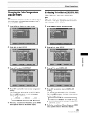
... settings are supported only with input signals from a video device. MAIN MENU INPUT1 PICTURE SET UP OPTION I NPUT L ABEL : I NPUT 1 AUT O P OWER OF F : OF F COL OR T EMP : M I DDL E D I G I T AL NR : LOW H I GH CON TRAS T : OF F P URE C I NEMA : OFF CL AMP P OS I T I ON : AU T O SETT I NG : V I DEO V I DEO S I GNAL : RGB SELECT SET CHANGE MENU EXIT 4 Press SET to the normal display. 29 PRO-1000HD / PRO-800HD Each time SET...
... settings are supported only with input signals from a video device. MAIN MENU INPUT1 PICTURE SET UP OPTION I NPUT L ABEL : I NPUT 1 AUT O P OWER OF F : OF F COL OR T EMP : M I DDL E D I G I T AL NR : LOW H I GH CON TRAS T : OF F P URE C I NEMA : OFF CL AMP P OS I T I ON : AU T O SETT I NG : V I DEO V I DEO S I GNAL : RGB SELECT SET CHANGE MENU EXIT 4 Press SET to the normal display. 29 PRO-1000HD / PRO-800HD Each time SET...
Owner's Manual
Page 35
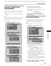
... viewing an image from the factory. The menu screen appears. MAIN MENU INPUT4 PICTURE SET UP OPTION I NPUT L ABEL : I NPUT 4 AUT O P OWER OF F : OF F COL OR T EMP : M I DDL E D I G I T AL NR : L OW H I GH CON TRAS T : OF F P URE C I NEMA : OFF 3 D Y / C MODE : MOT I XED 3 Press SET to be made independently for each input (INPUT 1 - Each time SET is pressed, the settings change in a bright location. Note The POWER CONTROL setting affects all input sources. 1 Press MENU...
... viewing an image from the factory. The menu screen appears. MAIN MENU INPUT4 PICTURE SET UP OPTION I NPUT L ABEL : I NPUT 4 AUT O P OWER OF F : OF F COL OR T EMP : M I DDL E D I G I T AL NR : L OW H I GH CON TRAS T : OF F P URE C I NEMA : OFF 3 D Y / C MODE : MOT I XED 3 Press SET to be made independently for each input (INPUT 1 - Each time SET is pressed, the settings change in a bright location. Note The POWER CONTROL setting affects all input sources. 1 Press MENU...
Owner's Manual
Page 37
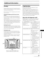
... plasma display. ¶ Cooling fan has malfunctioned. If there is no display check to unplug the power cord from its outlet, and consult a Pioneer service center or your dealer. 33 PRO-1000HD / PRO-800HD Additional Information About the self diagnosis mode Messages appear on again. Immediately turn off main power (page 7). ¶ Is ambient temperature too high? ¶ Remove any circumstances use solvents such as a video...
... plasma display. ¶ Cooling fan has malfunctioned. If there is no display check to unplug the power cord from its outlet, and consult a Pioneer service center or your dealer. 33 PRO-1000HD / PRO-800HD Additional Information About the self diagnosis mode Messages appear on again. Immediately turn off main power (page 7). ¶ Is ambient temperature too high? ¶ Remove any circumstances use solvents such as a video...

Owner's Manual
Page 38
... the video input signal's level is too high, the bright portions may cause improper operation. Allow condensation to dry thoroughly before using "SCREEN" mode on the screen. • Sound is heard from the cabinet. • Bright portions of the plasma display panel. If there is still no improvement, this case, operate the unit after first turning the main power switch on/off . • No picture...
... the video input signal's level is too high, the bright portions may cause improper operation. Allow condensation to dry thoroughly before using "SCREEN" mode on the screen. • Sound is heard from the cabinet. • Bright portions of the plasma display panel. If there is still no improvement, this case, operate the unit after first turning the main power switch on/off . • No picture...
Other Manual
Page 10
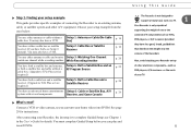
... cable box. You must complete Guided Setup before you can play and record DVDs. You may also have a VCR. You use either antenna or cable without a RF Program Source cable box. (Upgrade to TiVo Plus service required.) You have both , see Chapter 1 in the User's Guide for instructions. Receiver, and Game Console What's next? Step 2: Finding your setup example from the ones below: You use either antenna or cable and want to Setup 3: Watching One Channel...
... cable box. You must complete Guided Setup before you can play and record DVDs. You may also have a VCR. You use either antenna or cable without a RF Program Source cable box. (Upgrade to TiVo Plus service required.) You have both , see Chapter 1 in the User's Guide for instructions. Receiver, and Game Console What's next? Step 2: Finding your setup example from the ones below: You use either antenna or cable and want to Setup 3: Watching One Channel...
Other Manual
Page 15
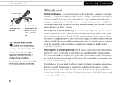
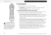
.... (See the diagram on the IR sensor and stick out about 1.5 inches. Choosing an IR code in Chapters 2 and 3). Position the IR emitters so they send an IR signal. Try changing channels several times with an IR Control cable is reliable or consistent, try the tips on the cable or satellite box are shaded from other infrared signals. During Guided Setup, you need to make...
.... (See the diagram on the IR sensor and stick out about 1.5 inches. Choosing an IR code in Chapters 2 and 3). Position the IR emitters so they send an IR signal. Try changing channels several times with an IR Control cable is reliable or consistent, try the tips on the cable or satellite box are shaded from other infrared signals. During Guided Setup, you need to make...
Other Manual
Page 20
... ). Connect the Composite A/V cable from the wall to select the correct audio/video source. See Chapter 8, "Connecting to the TiVo service. Press the button until the Welcome screen is to complete Guided Setup (see the Welcome screen displayed, use a shared 2 broadband Internet connection instead of a phone line to connect to a Home Network," in all power cords. 5. Turn on your Recorder to the Audio/Video Input connectors on the Pioneer DVD Recorder with TiVo. 2. Once you can play and record DVDs...
... ). Connect the Composite A/V cable from the wall to select the correct audio/video source. See Chapter 8, "Connecting to the TiVo service. Press the button until the Welcome screen is to complete Guided Setup (see the Welcome screen displayed, use a shared 2 broadband Internet connection instead of a phone line to connect to a Home Network," in all power cords. 5. Turn on your Recorder to the Audio/Video Input connectors on the Pioneer DVD Recorder with TiVo. 2. Once you can play and record DVDs...
Other Manual
Page 26
... screen, you see the User's Guide for details). If you 're ready for help , see the Welcome screen. Keep in all power cords. 6. In step 1, connect an RF Coaxial cable from the Audio/Video Output 1 connectors on the Recorder to the RF In connector on your Recorder again: First, press the TiVo button so that the Recorder displays TiVo Central®. Turn on the Pioneer DVD...
... screen, you see the User's Guide for details). If you 're ready for help , see the Welcome screen. Keep in all power cords. 6. In step 1, connect an RF Coaxial cable from the Audio/Video Output 1 connectors on the Recorder to the RF In connector on your Recorder again: First, press the TiVo button so that the Recorder displays TiVo Central®. Turn on the Pioneer DVD...
Other Manual
Page 28
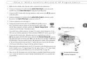
... line (see the Welcome screen, you still can play and record DVDs. If you need to the Audio/Video Input 1 connectors on your TV. Plug in place.) Recorder ® 8. Connect Composite A/V cables from the Audio/Video Output connectors on the satellite box to find the correct TV input setting. If your TV until you don't have DIRECTV service, go to the satellite box. 2. For tips on top of the Serial Control cable...
... line (see the Welcome screen, you still can play and record DVDs. If you need to the Audio/Video Input 1 connectors on your TV. Plug in place.) Recorder ® 8. Connect Composite A/V cables from the Audio/Video Output connectors on the satellite box to find the correct TV input setting. If your TV until you don't have DIRECTV service, go to the satellite box. 2. For tips on top of the Serial Control cable...
Other Manual
Page 30
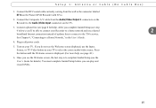
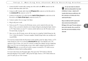
... screen, the last step is to the Audio/Video Input 1 connectors on your cable and satellite boxes. 2. Plug in front of the satellite box. The illustration above shows both emitters stick out about 1.5 inches directly in all power cords and turn on the Recorder. 3. Connect Composite A/V cables from the Audio/Video Output connectors on the IR Control cable connection, see the User's Guide for Serial control alternatives. Connect a phone line (page 8). 6. Once you don't have DIRECTV service...
... screen, the last step is to the Audio/Video Input 1 connectors on your cable and satellite boxes. 2. Plug in front of the satellite box. The illustration above shows both emitters stick out about 1.5 inches directly in all power cords and turn on the Recorder. 3. Connect Composite A/V cables from the Audio/Video Output connectors on the IR Control cable connection, see the User's Guide for Serial control alternatives. Connect a phone line (page 8). 6. Once you don't have DIRECTV service...

Other Manual
Page 33
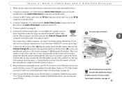
... currently see the Welcome screen, you see the Welcome screen, press the TV/Video, Source, or Input button on your TV until you 'll need to select a the input for your Recorder on your A/V receiver. (See the manual that cycles through the inputs. Be sure both emitters stick out about 1.5 inches directly in front of the IR Control cable into the Channel Change/IR connector (the...
... currently see the Welcome screen, you see the Welcome screen, press the TV/Video, Source, or Input button on your TV until you 'll need to select a the input for your Recorder on your A/V receiver. (See the manual that cycles through the inputs. Be sure both emitters stick out about 1.5 inches directly in front of the IR Control cable into the Channel Change/IR connector (the...
Other Manual
Page 37
... video signal-or "input"-your TV. Then repeat the instructions using the first column in each of the tables. The VOLUME and MUTE buttons control only the A/V receiver. • Control TV power and A/V stereo system volume and mute: Complete the instructions on /off the TV and the A/V receiver at the same time. You can also set it up to control your Pioneer DVD Recorder with TiVo. Changing the input changes the source of the User's Guide...
... video signal-or "input"-your TV. Then repeat the instructions using the first column in each of the tables. The VOLUME and MUTE buttons control only the A/V receiver. • Control TV power and A/V stereo system volume and mute: Complete the instructions on /off the TV and the A/V receiver at the same time. You can also set it up to control your Pioneer DVD Recorder with TiVo. Changing the input changes the source of the User's Guide...
Other Manual
Page 46
... Internet access to make its regular connection to the TiVo service and download updated program information, and additional information from the TiVo service, such as service updates. For more information, see Chapter 8, "Connecting to a Home Network," in the User's Guide. 41 This connection downloads program information, which includes up to date. • After Guided Setup, the Recorder can use a home network's shared broadband Internet connection to make its regular connections to the TiVo service. Troubleshooting Troubleshooting...
... Internet access to make its regular connection to the TiVo service and download updated program information, and additional information from the TiVo service, such as service updates. For more information, see Chapter 8, "Connecting to a Home Network," in the User's Guide. 41 This connection downloads program information, which includes up to date. • After Guided Setup, the Recorder can use a home network's shared broadband Internet connection to make its regular connections to the TiVo service. Troubleshooting Troubleshooting...
Other Manual
Page 57
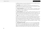
... connect to the TiVo service. Appendix 52 Appendix A 1 - AC ~ In: (Connects to A/C power.) The Recorder does not use a network's shared Internet connection to connect to a home network, then use a separate on the other end of the IR Control cable plugs into the wall socket switches it into the Recorder. Phone Line: (Connects to phone line.) The Recorder uses the phone line to get program listings and to cable or satellite box; If you need an Optical Digital Audio cable (not supplied). Channel Change/Serial: (Connects...
... connect to the TiVo service. Appendix 52 Appendix A 1 - AC ~ In: (Connects to A/C power.) The Recorder does not use a network's shared Internet connection to connect to a home network, then use a separate on the other end of the IR Control cable plugs into the wall socket switches it into the Recorder. Phone Line: (Connects to phone line.) The Recorder uses the phone line to get program listings and to cable or satellite box; If you need an Optical Digital Audio cable (not supplied). Channel Change/Serial: (Connects...


