Owner's Manual
Page 5
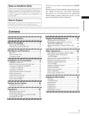
...Before using your dealer install and set up the product. Contents Safety Precautions i Before Proceeding 2 How to deliver this PIONEER product. Thank you will find it is installed by mistake in installation or mounting, misuse, modification or a natural ... This Manual 2 Checking Supplied Accessories 3 Part Names and Functions 4 Main Unit 4 Remote Control Unit 5 Connection Panel 6 Installation and Connections 8 Installation of Terms 39 1 PRO-1000HD / PRO-800HD PIONEER cannot assume liabilities for damage caused by qualified personnel with enough skill and competence.
...Before using your dealer install and set up the product. Contents Safety Precautions i Before Proceeding 2 How to deliver this PIONEER product. Thank you will find it is installed by mistake in installation or mounting, misuse, modification or a natural ... This Manual 2 Checking Supplied Accessories 3 Part Names and Functions 4 Main Unit 4 Remote Control Unit 5 Connection Panel 6 Installation and Connections 8 Installation of Terms 39 1 PRO-1000HD / PRO-800HD PIONEER cannot assume liabilities for damage caused by qualified personnel with enough skill and competence.
Owner's Manual
Page 6
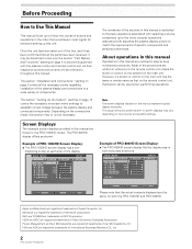
... the more complex operations associated with the plasma monitor and remote control unit, as shown: Example of PRO-1000HD Screen Display: ÷ The PRO-1000HD screen display has a non- L EVEL G. Note The screen displays depicted in this manual represent typical display examples. The PRO-800HD display differs as their respective buttons and controls will be...
... the more complex operations associated with the plasma monitor and remote control unit, as shown: Example of PRO-1000HD Screen Display: ÷ The PRO-1000HD screen display has a non- L EVEL G. Note The screen displays depicted in this manual represent typical display examples. The PRO-800HD display differs as their respective buttons and controls will be...

Owner's Manual
Page 7
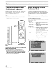
... MENU PICTURE SCREEN CONT RAST BR I ON : 0 ADJUST MENU SET EXIT SET 5 Press 5/∞/2/3 to adjust the value. ÷ Operating Instructions ÷ Warranty 3 PRO-1000HD / PRO-800HD L E V E L B. Please familiarize yourself with this process before continuing on with the rest of the screen. E NHANCE V. ENHANCE :0 :0 : +60 : +.... 1 Press MENU to select SCREEN. Before Proceeding Before Proceeding The following accessories were supplied. 1 Power cord 2 Remote control unit 3 AA (R6) batteries (x 2) VIDEO S-VIDEO SELECT SET ENTER MENU EXIT 3 Press 5/∞ to select the ...
... MENU PICTURE SCREEN CONT RAST BR I ON : 0 ADJUST MENU SET EXIT SET 5 Press 5/∞/2/3 to adjust the value. ÷ Operating Instructions ÷ Warranty 3 PRO-1000HD / PRO-800HD L E V E L B. Please familiarize yourself with this process before continuing on with the rest of the screen. E NHANCE V. ENHANCE :0 :0 : +60 : +.... 1 Press MENU to select SCREEN. Before Proceeding Before Proceeding The following accessories were supplied. 1 Power cord 2 Remote control unit 3 AA (R6) batteries (x 2) VIDEO S-VIDEO SELECT SET ENTER MENU EXIT 3 Press 5/∞ to select the ...
Owner's Manual
Page 8
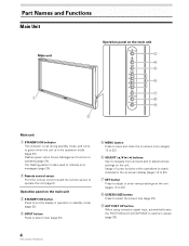
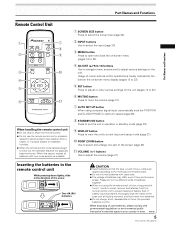
Usage of cursor buttons within operations is also used to indicate error messages (page 35). 2 Remote control sensor Point the remote control toward the remote sensor to operate the unit (page 6). The flashing pattern is clearly indicated in the on-screen display (pages 18 to 32). 7 SET ... 22). 9 AUTO SET UP button When using computer signal input, automatically sets the POSITION and CLOCK/PHASE to optimum values (page 26). 4 PRO-1000HD / PRO-800HD Operation panel on the main unit 3 STANDBY/ON button Press to put the display in the operation mode (page 20). Part Names and Functions Main...
Usage of cursor buttons within operations is also used to indicate error messages (page 35). 2 Remote control sensor Point the remote control toward the remote sensor to operate the unit (page 6). The flashing pattern is clearly indicated in the on-screen display (pages 18 to 32). 7 SET ... 22). 9 AUTO SET UP button When using computer signal input, automatically sets the POSITION and CLOCK/PHASE to optimum values (page 26). 4 PRO-1000HD / PRO-800HD Operation panel on the main unit 3 STANDBY/ON button Press to put the display in the operation mode (page 20). Part Names and Functions Main...
Owner's Manual
Page 9
... to mute the volume (page 21). 7 AUTO SET UP button When using the remote control unit for a long period of the screen (page 23). - Part Names and Functions Part Names and Functions Remote Control Unit 1 7 8 2 S-VIDEO VIDEO 9 3 0 4 5 6 - H048 En 5 PRO-1000HD / PRO-800HD Two AA (R6) batteries CAUTION ¶ Insert batteries so that apply in...
... to mute the volume (page 21). 7 AUTO SET UP button When using the remote control unit for a long period of the screen (page 23). - Part Names and Functions Part Names and Functions Remote Control Unit 1 7 8 2 S-VIDEO VIDEO 9 3 0 4 5 6 - H048 En 5 PRO-1000HD / PRO-800HD Two AA (R6) batteries CAUTION ¶ Insert batteries so that apply in...
Owner's Manual
Page 10
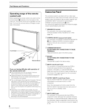
... deck or other component. The strength of infrared rays discharged from the screen will differ according to the picture displayed. 6 PRO-1000HD / PRO-800HD Connection Panel The connection panel is provided with a CONTROL IN/OUT connector for connecting to an external monitor or other component ...on each item. 1 SPEAKER (R) terminal For connection of PIONEER components that component's reception of the remote control's signal, or prevent it at the remote sensor (Î) located on the front panel of the main unit. The remote control unit is operable up to a position further away from...
... deck or other component. The strength of infrared rays discharged from the screen will differ according to the picture displayed. 6 PRO-1000HD / PRO-800HD Connection Panel The connection panel is provided with a CONTROL IN/OUT connector for connecting to an external monitor or other component ...on each item. 1 SPEAKER (R) terminal For connection of PIONEER components that component's reception of the remote control's signal, or prevent it at the remote sensor (Î) located on the front panel of the main unit. The remote control unit is operable up to a position further away from...
Owner's Manual
Page 19
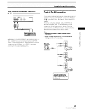
... when making connections. ÷ Please complete all component connections before making control cord connections. When the connection is made , remote control operation of connected PIONEER components that component will no resistance). 15 PRO-1000HD / PRO-800HD Installation and Connections Control Cord Connection When control cord connections are monaural cables with mini plugs (no longer receive...
... when making connections. ÷ Please complete all component connections before making control cord connections. When the connection is made , remote control operation of connected PIONEER components that component will no resistance). 15 PRO-1000HD / PRO-800HD Installation and Connections Control Cord Connection When control cord connections are monaural cables with mini plugs (no longer receive...

Owner's Manual
Page 24
...remote control unit or the main unit to select connected components. Before you begin, make sure you have: • Made connections between this unit in the operation or standby mode and how to select the input. The STANDBY/ON indicator turns green. 20 PRO-1000HD / PRO-800HD... 77. 1 kH z f V : 85. 0 Hz 115 2X864 2,5 3 S-VIDEO VIDEO 2,5 3 FULL I NPUT1 CAUT I O N OUT OF R ANG E f H : 75. 7 kH z f V :120. 0 Hz ---- 4 Main Unit Operating Panel Remote Control Unit 1 Switch the main power switch on the main unit to the on position to turn off. • If the input computer signal is...
...remote control unit or the main unit to select connected components. Before you begin, make sure you have: • Made connections between this unit in the operation or standby mode and how to select the input. The STANDBY/ON indicator turns green. 20 PRO-1000HD / PRO-800HD... 77. 1 kH z f V : 85. 0 Hz 115 2X864 2,5 3 S-VIDEO VIDEO 2,5 3 FULL I NPUT1 CAUT I O N OUT OF R ANG E f H : 75. 7 kH z f V :120. 0 Hz ---- 4 Main Unit Operating Panel Remote Control Unit 1 Switch the main power switch on the main unit to the on position to turn off. • If the input computer signal is...

Owner's Manual
Page 25
.... Press VOLUME + or VOLUME - Use VOLUME + or VOLUME - V OLU ME :5 To mute the sound Press DISPLAY on the remote control unit. Press MUTING again to adjust the volume at a desired level. 21 PRO-1000HD / PRO-800HD to restore the sound. Muting is automatically canceled about 3 seconds. The currently selected input, screen size and refresh...
.... Press VOLUME + or VOLUME - Use VOLUME + or VOLUME - V OLU ME :5 To mute the sound Press DISPLAY on the remote control unit. Press MUTING again to adjust the volume at a desired level. 21 PRO-1000HD / PRO-800HD to restore the sound. Muting is automatically canceled about 3 seconds. The currently selected input, screen size and refresh...
Owner's Manual
Page 27
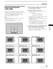
... Press SET to FULL. 1 Press the remote control unit's POINT ZOOM. AREA 1 display range AREA 1 x 4.0 x 2.0 x 1.5 x 3.0 AREA 2 display range AREA 2 x 4.0 x 2.0 x 1.5 AREA 3 display range x 3.0 x 3.0 AREA 3 x 4.0 x 2.0 x 1.5 AREA 4 display range AREA 5 display range AREA 6 display range AREA 4 x 4.0 x 2.0 x 1.5 x 3.0 AREA 7 display range AREA 5 x 4.0 x 2.0 x 1.5 AREA 8 display range x 3.0 x 3.0 AREA 6 x 4.0 x 2.0 x 1.5 AREA 9 display range AREA 7 x 4.0 x 2.0 x 1.5 x 3.0 AREA 8 x 4.0 x 2.0 x 1.5 x 3.0 x 3.0 AREA 9 x 4.0 x 2.0 x 1.5 23 PRO-1000HD / PRO-800HD
... Press SET to FULL. 1 Press the remote control unit's POINT ZOOM. AREA 1 display range AREA 1 x 4.0 x 2.0 x 1.5 x 3.0 AREA 2 display range AREA 2 x 4.0 x 2.0 x 1.5 AREA 3 display range x 3.0 x 3.0 AREA 3 x 4.0 x 2.0 x 1.5 AREA 4 display range AREA 5 display range AREA 6 display range AREA 4 x 4.0 x 2.0 x 1.5 x 3.0 AREA 7 display range AREA 5 x 4.0 x 2.0 x 1.5 AREA 8 display range x 3.0 x 3.0 AREA 6 x 4.0 x 2.0 x 1.5 AREA 9 display range AREA 7 x 4.0 x 2.0 x 1.5 x 3.0 AREA 8 x 4.0 x 2.0 x 1.5 x 3.0 x 3.0 AREA 9 x 4.0 x 2.0 x 1.5 23 PRO-1000HD / PRO-800HD

Owner's Manual
Page 28
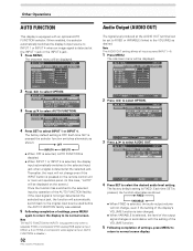
... OS I T I ON : AU T O SETT I NG : VGA SELECT SET ENTER MENU EXIT 24 PRO-1000HD / PRO-800HD 3 Press 5/∞ to select either operate the computer, or press INPUT on the main unit operating panel or remote control unit. ÷ To return to normal operation from AUTO POWER OFF mode: Press STANDBY/ON...display will be set individually for each input (INPUT 1-4). Except when input signal is G on the main unit operating panel or remote control unit. Operations Automatic Power OFF This display is equipped with automatic powermanagement and auto-power-off the plasma display's main power ...
... OS I T I ON : AU T O SETT I NG : VGA SELECT SET ENTER MENU EXIT 24 PRO-1000HD / PRO-800HD 3 Press 5/∞ to select either operate the computer, or press INPUT on the main unit operating panel or remote control unit. ÷ To return to normal operation from AUTO POWER OFF mode: Press STANDBY/ON...display will be set individually for each input (INPUT 1-4). Except when input signal is G on the main unit operating panel or remote control unit. Operations Automatic Power OFF This display is equipped with automatic powermanagement and auto-power-off the plasma display's main power ...
Owner's Manual
Page 30
... H.POSITION Adjust the picture's position to optimum values. CLOCK/PHASE CLOCK Adjust letter breakup or noise on either the main unit operating panel or the remote control unit will adjust the screen position and clock to the left or right. L EVEL G. ENHANCE :0 :0 : +60 : +60 : +60 :0...VIDEO VIDEO AUTO SET UP Main Unit Operating Panel Remote Control Unit Press AUTO SET UP on the screen. MAIN MENU PICTURE SCREEN CONT RAST BR I ON : CL OCK / PHASE : SET UP 0/ 0 0/ 0 RE S ET INPUT1 OPTION 26 PRO-1000HD / PRO-800HD SELECT SET ENTER MENU EXIT MAIN MENU PICTURE SCREEN...
... H.POSITION Adjust the picture's position to optimum values. CLOCK/PHASE CLOCK Adjust letter breakup or noise on either the main unit operating panel or the remote control unit will adjust the screen position and clock to the left or right. L EVEL G. ENHANCE :0 :0 : +60 : +60 : +60 :0...VIDEO VIDEO AUTO SET UP Main Unit Operating Panel Remote Control Unit Press AUTO SET UP on the screen. MAIN MENU PICTURE SCREEN CONT RAST BR I ON : CL OCK / PHASE : SET UP 0/ 0 0/ 0 RE S ET INPUT1 OPTION 26 PRO-1000HD / PRO-800HD SELECT SET ENTER MENU EXIT MAIN MENU PICTURE SCREEN...
Owner's Manual
Page 36
... not change even if the INPUT button is pressed on the remote control unit or main unit operation panel. (In this case, "AUTO" will be displayed on SYNC or component video signal is input, AUTO FUNCTION is disable.) 32 PRO-1000HD / PRO-800HD Audio Output (AUDIO OUT) The signal level produced at the INPUT...
... not change even if the INPUT button is pressed on the remote control unit or main unit operation panel. (In this case, "AUTO" will be displayed on SYNC or component video signal is input, AUTO FUNCTION is disable.) 32 PRO-1000HD / PRO-800HD Audio Output (AUDIO OUT) The signal level produced at the INPUT...
Owner's Manual
Page 37
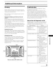
... displayed, refer to the table below . The problem may be sure to unplug the power cord from its outlet and consult a Pioneer service center or your dealer. After message confirmation, check the condition of dust will extend the life and performance of this unit's ...vacuum cleaner to its outlet, and consult a Pioneer service center or your dealer. 33 PRO-1000HD / PRO-800HD Additional Information Immediately turn off power, remove power plug from the display or remote control unit. Cleaning the display panel body and remote control Do not under any objects blocking the cooling...
... displayed, refer to the table below . The problem may be sure to unplug the power cord from its outlet and consult a Pioneer service center or your dealer. After message confirmation, check the condition of dust will extend the life and performance of this unit's ...vacuum cleaner to its outlet, and consult a Pioneer service center or your dealer. 33 PRO-1000HD / PRO-800HD Additional Information Immediately turn off power, remove power plug from the display or remote control unit. Cleaning the display panel body and remote control Do not under any objects blocking the cooling...

Owner's Manual
Page 38
..., static electricity, etc., may result in sound being used ? (page 32) • Is the selected screen size correct? Not a malfunction. 34 PRO-1000HD / PRO-800HD Not a malfunction. • Fan is set to ON? (page 24). • Condensation has formed on the menu screen (pages 26, 27). ...• Fan isn't moving • Fan speed changes. Additional Information General problems Problem • No power • Unit cannot be operated. • Remote control does not operate. • INPUT is not changed. • Picture is cut off. • Strange color, light color, or dark, or color...
..., static electricity, etc., may result in sound being used ? (page 32) • Is the selected screen size correct? Not a malfunction. 34 PRO-1000HD / PRO-800HD Not a malfunction. • Fan is set to ON? (page 24). • Condensation has formed on the menu screen (pages 26, 27). ...• Fan isn't moving • Fan speed changes. Additional Information General problems Problem • No power • Unit cannot be operated. • Remote control does not operate. • INPUT is not changed. • Picture is cut off. • Strange color, light color, or dark, or color...
Owner's Manual
Page 40
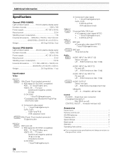
.../positive and negative polarity/ 75 Ω or 2.2 kΩ (impedance switch) G ON SYNC ... 1 Vp-p/75 Ω/negative sync. 36 PRO-1000HD / PRO-800HD 2 Component video signal Y ... 1 Vp-p/75 Ω/negative sync. CB/PB, CR/PR ... 0.525 Vp-p/75 Ω (75% satulation ... ...... 1111 (W) x 692 (H) x 104 (D) mm 43-3/4 (W) x 27-1/4 (H) x 4 (D) in . monaural mini jack (x2) Accessories Power cord 1 Remote control unit 1 AA (R6) batteries 2 Cleaning cloth 1 Speed clamps 2 Bead bands 2 Warranty 1 Operating Instructions 1 ÷ Due to improvements, specifications and design...
.../positive and negative polarity/ 75 Ω or 2.2 kΩ (impedance switch) G ON SYNC ... 1 Vp-p/75 Ω/negative sync. 36 PRO-1000HD / PRO-800HD 2 Component video signal Y ... 1 Vp-p/75 Ω/negative sync. CB/PB, CR/PR ... 0.525 Vp-p/75 Ω (75% satulation ... ...... 1111 (W) x 692 (H) x 104 (D) mm 43-3/4 (W) x 27-1/4 (H) x 4 (D) in . monaural mini jack (x2) Accessories Power cord 1 Remote control unit 1 AA (R6) batteries 2 Cleaning cloth 1 Speed clamps 2 Bead bands 2 Warranty 1 Operating Instructions 1 ÷ Due to improvements, specifications and design...
Other Manual
Page 4
... Box and a Satellite Receiver 24 Setup 6: Cable or Satellite Box, A/V Receiver, and Game Console 26 Connecting a VCR or a Video Camera 29 Chapter 4: Setting Up the Remote Control 31 Introduction 32 Instructions: Power, Volume, Mute, TV Input 33 Managing Multiple Recorders and...
... Box and a Satellite Receiver 24 Setup 6: Cable or Satellite Box, A/V Receiver, and Game Console 26 Connecting a VCR or a Video Camera 29 Chapter 4: Setting Up the Remote Control 31 Introduction 32 Instructions: Power, Volume, Mute, TV Input 33 Managing Multiple Recorders and...
Other Manual
Page 11
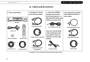
... DVD op Men Live TV Guide Info Menu Select Window Vol Mute Chan Page Record Return Play V CR Plus + Slow Clear 1 Stop Enter 2 3 4 5 6 7 8 9 V Pow T 0 V Inpu t Remote Control Composite A/V cables Serial (Data) Control cable* S-Video cable (not supplied) If you have a DIRECTV 4. These are the basics: Recorder 2.
... DVD op Men Live TV Guide Info Menu Select Window Vol Mute Chan Page Record Return Play V CR Plus + Slow Clear 1 Stop Enter 2 3 4 5 6 7 8 9 V Pow T 0 V Inpu t Remote Control Composite A/V cables Serial (Data) Control cable* S-Video cable (not supplied) If you have a DIRECTV 4. These are the basics: Recorder 2.
Other Manual
Page 14
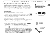
... to try to connect a Home Control cable to the satellite receiver's phone jack.) Plug the other end into the Home Control jack on your Recorder's remote control only.
... to try to connect a Home Control cable to the satellite receiver's phone jack.) Plug the other end into the Home Control jack on your Recorder's remote control only.
Other Manual
Page 15
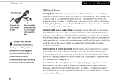
... Getting Started IR (Infrared) Control Finding the IR sensor. If you see below). Test whether an IR cover might help if changing channels with the remote control. If channels change at all. Chapter 1 IR Control cable This purple end plugs into your cable or satellite box. To locate the IR sensor...
... Getting Started IR (Infrared) Control Finding the IR sensor. If you see below). Test whether an IR cover might help if changing channels with the remote control. If channels change at all. Chapter 1 IR Control cable This purple end plugs into your cable or satellite box. To locate the IR sensor...


