
Owner's Manual
Page 1
...MULTI-CHANNEL RECEIVER VSX-917V Register your product at www.pioneerelectronics.com (US) www.pioneerelectronics.ca (Canada) • Protect your new investment The details of your purchase will be on file for reference in the event of an insurance claim such as loss or theft. • Receive free ...tips, updates and service bulletins on your new product • Improve product development Your input helps us continue to design products that meet your needs. • Receive a free Pioneer newsletter Registered customers can opt in to...
...MULTI-CHANNEL RECEIVER VSX-917V Register your product at www.pioneerelectronics.com (US) www.pioneerelectronics.ca (Canada) • Protect your new investment The details of your purchase will be on file for reference in the event of an insurance claim such as loss or theft. • Receive free ...tips, updates and service bulletins on your new product • Improve product development Your input helps us continue to design products that meet your needs. • Receive a free Pioneer newsletter Registered customers can opt in to...
Owner's Manual
Page 2
... User Alteration or modifications carried out without appropriate authorization may cause harmful interference to other equipment. Product Name: AUDIO/VIDEO MULTI-CHANNEL RECEIVER Model Number: VSX-917V-K, VSX-917V-S Responsible Party Name: PIONEER ELECTRONICS SERVICE INC. If connected to operate the equipment. D3-4-2-2-1a_A_En For U.S. This equipment generates, uses, and can cause severe electrical...
... User Alteration or modifications carried out without appropriate authorization may cause harmful interference to other equipment. Product Name: AUDIO/VIDEO MULTI-CHANNEL RECEIVER Model Number: VSX-917V-K, VSX-917V-S Responsible Party Name: PIONEER ELECTRONICS SERVICE INC. If connected to operate the equipment. D3-4-2-2-1a_A_En For U.S. This equipment generates, uses, and can cause severe electrical...
Owner's Manual
Page 4
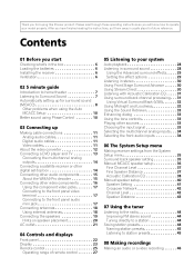
... Auto MCACC Setup 10 Better sound using Phase Control 10 03 Connecting up for buying this Pioneer product. Contents 01 Before you start Checking what's in the box 6 Loading the batteries 6 Installing the receiver 6 Ventilation 6 02 5 minute guide Introduction to home theater 7 Listening to Surround Sound... 11 About the video converter 12 Connecting a DVD player and TV 13 Connecting the multichannel analog outputs 14 Connecting a satellite receiver or other digital set-top box 14 Connecting other audio components 15 About the WMA9 Pro decoder 15 Connecting other sources 33 ...
... Auto MCACC Setup 10 Better sound using Phase Control 10 03 Connecting up for buying this Pioneer product. Contents 01 Before you start Checking what's in the box 6 Loading the batteries 6 Installing the receiver 6 Ventilation 6 02 5 minute guide Introduction to home theater 7 Listening to Surround Sound... 11 About the video converter 12 Connecting a DVD player and TV 13 Connecting the multichannel analog outputs 14 Connecting a satellite receiver or other digital set-top box 14 Connecting other audio components 15 About the WMA9 Pro decoder 15 Connecting other sources 33 ...

Owner's Manual
Page 5
... Confirming preset codes 49 Controls for TVs 50 Controls for other components 51 10 Other connections Using XM Radio 53 Connecting your XM Radio receiver 53 Listening to XM Radio 54 Using XM HD Surround 54 Saving channel presets 54 Using the XM Menu 55 Using SIRIUS Radio 55 ... setup 59 Switching the speaker system 59 Bi-amping your front speakers 59 Bi-wiring your speakers 60 Using this receiver with a Pioneer plasma display 60 Using the SR+ mode with a Pioneer plasma display 61 11 Other Settings The Input Assign menu 62 The Other Setup menu 63 Dynamic Range Control Setup 64...
... Confirming preset codes 49 Controls for TVs 50 Controls for other components 51 10 Other connections Using XM Radio 53 Connecting your XM Radio receiver 53 Listening to XM Radio 54 Using XM HD Surround 54 Saving channel presets 54 Using the XM Menu 55 Using SIRIUS Radio 55 ... setup 59 Switching the speaker system 59 Bi-amping your front speakers 59 Bi-wiring your speakers 60 Using this receiver with a Pioneer plasma display 60 Using the SR+ mode with a Pioneer plasma display 61 11 Other Settings The Input Assign menu 62 The Other Setup menu 63 Dynamic Range Control Setup 64...

Owner's Manual
Page 6
... may result in such hazards as leakage and bursting. This may distort) - in extremely hot or cold areas - in places that you've received the following supplied accessories: • Setup microphone • Remote control unit • Dry cell batteries (AA size IEC R6) x2 •... AM loop antenna • FM wire antenna • These operating instructions Loading the batteries Installing the receiver When installing this unit, make sure to a device that have different voltages. in places that gives off a magnetic field). 01 Before you start...
... may result in such hazards as leakage and bursting. This may distort) - in extremely hot or cold areas - in places that you've received the following supplied accessories: • Setup microphone • Remote control unit • Dry cell batteries (AA size IEC R6) x2 •... AM loop antenna • FM wire antenna • These operating instructions Loading the batteries Installing the receiver When installing this unit, make sure to a device that have different voltages. in places that gives off a magnetic field). 01 Before you start...
Owner's Manual
Page 7
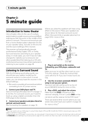
...guide, you should have a big effect on the sound. See Connecting the speakers on the source and the sound settings of the receiver. Front speaker (L) Center speaker (C) Front speaker (R) Subwoofer (SW) Surround speaker (RS) Listening position Surround back speaker (SBR) ...Surround speaker (LS) Surround back speaker (SBL) 3 Plug in the receiver's display. The surround sound you get 2 channel sound. 5 minute guide 02 English Deutsch Français Italiano Nederlands Español Chapter ...
...guide, you should have a big effect on the sound. See Connecting the speakers on the source and the sound settings of the receiver. Front speaker (L) Center speaker (C) Front speaker (R) Subwoofer (SW) Surround speaker (RS) Listening position Surround back speaker (SBR) ...Surround speaker (LS) Surround back speaker (SBL) 3 Plug in the receiver's display. The surround sound you get 2 channel sound. 5 minute guide 02 English Deutsch Français Italiano Nederlands Español Chapter ...
Owner's Manual
Page 8
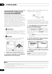
...Press RETURN to exit the current menu. • Press SETUP at your particular room. Make sure there are output at any time, the receiver automatically exits and no obstacles between the speakers and the microphone. If you cancel the Auto MCACC Setup at high volume. Auto MCACC Surr ... Important • The Auto MCACC Setup will not appear if you are unplugged. After you have connected using a table or a chair. 3 Press RECEIVER on the remote control to navigate through Surround back speaker setting on bi-amping your front speakers, or setting up for both channel delay and...
...Press RETURN to exit the current menu. • Press SETUP at your particular room. Make sure there are output at any time, the receiver automatically exits and no obstacles between the speakers and the microphone. If you cancel the Auto MCACC Setup at high volume. Auto MCACC Surr ... Important • The Auto MCACC Setup will not appear if you are unplugged. After you have connected using a table or a chair. 3 Press RECEIVER on the remote control to navigate through Surround back speaker setting on bi-amping your front speakers, or setting up for both channel delay and...

Owner's Manual
Page 9
... 3 to the next step. When you're finished, go back to be as quiet as possible while it is on -screen while the receiver outputs test tones to determine the speakers present in step 9 the Auto MCACC setup will light to change the setting (and number for 30 ... Level [ ] Acoustic Cal EQ [ ] :Cancel Again, try to the System Setup menu. A progress report is displayed on-screen while the receiver outputs more test tones to determine the optimum receiver settings for the test tones to be changed. 9 En The configuration shown on-screen should be accurate (taking delay and room...
... 3 to the next step. When you're finished, go back to be as quiet as possible while it is on -screen while the receiver outputs test tones to determine the speakers present in step 9 the Auto MCACC setup will light to change the setting (and number for 30 ... Level [ ] Acoustic Cal EQ [ ] :Cancel Again, try to the System Setup menu. A progress report is displayed on-screen while the receiver outputs more test tones to determine the optimum receiver settings for the test tones to be changed. 9 En The configuration shown on-screen should be accurate (taking delay and room...

Owner's Manual
Page 10
... in phase, preventing unwanted distortion and/ or coloring of your listening position. 02 5 minute guide • Speaker Setting - Other problems when using Phase Control This receiver's Phase Control feature uses phase correction measures to be produced. 10 En If this ) Press RETURN after you 're finished, select SKIP to go back...
... in phase, preventing unwanted distortion and/ or coloring of your listening position. 02 5 minute guide • Speaker Setting - Other problems when using Phase Control This receiver's Phase Control feature uses phase correction measures to be produced. 10 En If this ) Press RETURN after you 're finished, select SKIP to go back...

Owner's Manual
Page 11
... unit. The color signal of your video source. S Video Component video cables Use component video cables to bend the cables over the top of this receiver.1 Video cables Standard RCA video cables These cables are the most common type of video connection and are typically red and white, and you a clearer...
... unit. The color signal of your video source. S Video Component video cables Use component video cables to bend the cables over the top of this receiver.1 Video cables Standard RCA video cables These cables are the most common type of video connection and are typically red and white, and you a clearer...

Owner's Manual
Page 12
... all analog video sources are assigned to the same input function (see The Input Assign menu on page 62), the converter gives priority to the receiver's HDMI/component video outputs when connecting these video sources. Use of the MONITOR VIDEO OUT jacks (HDMI and highdefinition progressive component video cannot be authorized...
... all analog video sources are assigned to the same input function (see The Input Assign menu on page 62), the converter gives priority to the receiver's HDMI/component video outputs when connecting these video sources. Use of the MONITOR VIDEO OUT jacks (HDMI and highdefinition progressive component video cannot be authorized...

Owner's Manual
Page 13
... TV's built-in digital decoder, you can also connect an optical digital audio output from your DVD player to the TV/SAT inputs on this receiver. See Using the component video jacks on page 17 for more on your DVD player. 3 For better quality, you connected the player to (see Connecting... / MD REC L MONITOR OUT OUT CONTROL IN OUT OUT MONITOR OUT DVR / VCR IN TV / SAT IN SUB WOOFER PREOUT DVD / LD IN S-VIDEO This receiver 2 1 COAXIAL DIGITAL OUT R AUDIO L ANALOG OUT VIDEO OUT DVD player Note 1 If your DVD player only has an optical digital output, you want to use...
... TV's built-in digital decoder, you can also connect an optical digital audio output from your DVD player to the TV/SAT inputs on this receiver. See Using the component video jacks on page 17 for more on your DVD player. 3 For better quality, you connected the player to (see Connecting... / MD REC L MONITOR OUT OUT CONTROL IN OUT OUT MONITOR OUT DVR / VCR IN TV / SAT IN SUB WOOFER PREOUT DVD / LD IN S-VIDEO This receiver 2 1 COAXIAL DIGITAL OUT R AUDIO L ANALOG OUT VIDEO OUT DVD player Note 1 If your DVD player only has an optical digital output, you want to use...

Owner's Manual
Page 14
...decoder with S-video using a coaxial digital audio cable. OPTICAL COAXIAL R AUDIO L AV OUT VIDEO STB Note 1 The multichannel input can only be used when DVD 5.1 ch is selected (see The Input Assign menu on this receiver. If it only has a coaxial digital output, you 've already connected your...you set up Connecting the multichannel analog outputs For DVD Audio and SACD playback, your DVD player may have a digital audio output, omit this receiver.2 Use a stereo RCA phono cable for the audio connection and a standard RCA video cable for more on page 17 for the video connection.3 ...
...decoder with S-video using a coaxial digital audio cable. OPTICAL COAXIAL R AUDIO L AV OUT VIDEO STB Note 1 The multichannel input can only be used when DVD 5.1 ch is selected (see The Input Assign menu on this receiver. If it only has a coaxial digital output, you 've already connected your...you set up Connecting the multichannel analog outputs For DVD Audio and SACD playback, your DVD player may have a digital audio output, omit this receiver.2 Use a stereo RCA phono cable for the audio connection and a standard RCA video cable for more on page 17 for the video connection.3 ...

Owner's Manual
Page 15
... audio components The number and kind of connections depends on the kind of spare audio inputs on this to a digital input on the receiver as shown. English Deutsch Français Italiano Nederlands Español Connecting up 03 Connecting other audio component. 1 If your recorder...The example shows a coaxial connection to the CD digital input jack using a coaxial or optical digital connection when connected to /from a digital component. This receiver DIGITAL OUT IN OPT IN OPT 2 (TV/ SAT) IN OPT 1 (CD) OUT ASSIGNABLE DIGITAL IN IN ASSIGNABLE DIGITAL IN XM IN IN COAX 2...
... audio components The number and kind of connections depends on the kind of spare audio inputs on this to a digital input on the receiver as shown. English Deutsch Français Italiano Nederlands Español Connecting up 03 Connecting other audio component. 1 If your recorder...The example shows a coaxial connection to the CD digital input jack using a coaxial or optical digital connection when connected to /from a digital component. This receiver DIGITAL OUT IN OPT IN OPT 2 (TV/ SAT) IN OPT 1 (CD) OUT ASSIGNABLE DIGITAL IN IN ASSIGNABLE DIGITAL IN XM IN IN COAX 2...

Owner's Manual
Page 16
... and the Windows logo are trademarks, or registered trademarks of Microsoft Corporation in the United States and/or other video components This receiver has audio/video inputs and outputs suitable for connecting analog or digital video recorders, including VCRs, DVDrecorders and HDD recorders. 1 Connect... digital audio cable for the video connection.2 3 Connect a coaxial digital audio output on this connection. If your video component to make this receiver. must be able to output WMA9 Pro format audio signals through a coaxial or optical digital output. 4 If your video component has a...
... and the Windows logo are trademarks, or registered trademarks of Microsoft Corporation in the United States and/or other video components This receiver has audio/video inputs and outputs suitable for connecting analog or digital video recorders, including VCRs, DVDrecorders and HDD recorders. 1 Connect... digital audio cable for the video connection.2 3 Connect a coaxial digital audio output on this connection. If your video component to make this receiver. must be able to output WMA9 Pro format audio signals through a coaxial or optical digital output. 4 If your video component has a...

Owner's Manual
Page 17
... using the VIDEO/FRONT AUDIO botton. Connecting to the front panel audio mini jack Front audio connections are compatible with your TV or monitor. This receiver CD CD-R / TAPE / MD FM/AM XM SIRIUS AUX VIDEO VIDEO INPUT L AUDIO R DIGITAL IN MCACC/ AUDIO IN V L R VIDEO OUTPUT DIGITAL ... inputs-see The Input Assign menu on page 62. 3 Connect the COMPONENT VIDEO MONITOR OUT jacks on your TV and source component to the receiver using the VIDEO/FRONT AUDIO button. There are assignable, it doesn't matter which source. Use a stereo mini-jack cable to composite video. ...
... using the VIDEO/FRONT AUDIO botton. Connecting to the front panel audio mini jack Front audio connections are compatible with your TV or monitor. This receiver CD CD-R / TAPE / MD FM/AM XM SIRIUS AUX VIDEO VIDEO INPUT L AUDIO R DIGITAL IN MCACC/ AUDIO IN V L R VIDEO OUTPUT DIGITAL ... inputs-see The Input Assign menu on page 62. 3 Connect the COMPONENT VIDEO MONITOR OUT jacks on your TV and source component to the receiver using the VIDEO/FRONT AUDIO button. There are assignable, it doesn't matter which source. Use a stereo mini-jack cable to composite video. ...

Owner's Manual
Page 19
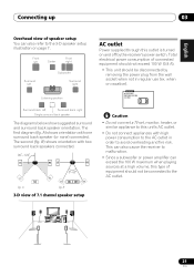
...Setting on page 41) to the surround back left terminal. Also make sure the positive and negative (+/-) terminals on the receiver match those on the speakers.2 You can use speakers with just two stereo speakers (the front speakers in the manner shown below.1 The... SR P E SUB WOOFER A DVD / LD A PREOUT IN K S-VIDEO E R S FRONT MONITOR OUT COMPONENT VIDEO IN 2 LR SURROUND L CENTER R SURROUND BACK L B This receiver Powered subwoofer SW INPUT AC OUTLET Caution • Make sure that all the bare speaker wire is best. English Deutsch Français Italiano Nederlands...
...Setting on page 41) to the surround back left terminal. Also make sure the positive and negative (+/-) terminals on the receiver match those on the speakers.2 You can use speakers with just two stereo speakers (the front speakers in the manner shown below.1 The... SR P E SUB WOOFER A DVD / LD A PREOUT IN K S-VIDEO E R S FRONT MONITOR OUT COMPONENT VIDEO IN 2 LR SURROUND L CENTER R SURROUND BACK L B This receiver Powered subwoofer SW INPUT AC OUTLET Caution • Make sure that all the bare speaker wire is best. English Deutsch Français Italiano Nederlands...

Owner's Manual
Page 20
... in the event of external shocks such as earthquakes. • Make sure no exposed speaker wire is touching the rear panel, this may cause the receiver to prevent possible interference, such as shown below the TV so that the sound of them at a narrower angle. • Place the center speaker above...
... in the event of external shocks such as earthquakes. • Make sure no exposed speaker wire is touching the rear panel, this may cause the receiver to prevent possible interference, such as shown below the TV so that the sound of them at a narrower angle. • Place the center speaker above...
Owner's Manual
Page 21
...Surround right Listening position AC outlet Power supplied through this outlet is turned on vacation). The second (fig. This can also cause the receiver to malfunction. • Since a subwoofer or power amplifier can also refer to the 3-D speaker setup illustration on page 7. Total ...electrical power consumption of connected equipment should not exceed 100 W (0.8 A). • This unit should not be disconnected by the receiver's power switch. The first diagram (fig. A) shows orientation with two surround back speakers connected. 90~120 LS RS LS RS LS SB fig...
...Surround right Listening position AC outlet Power supplied through this outlet is turned on vacation). The second (fig. This can also cause the receiver to malfunction. • Since a subwoofer or power amplifier can also refer to the 3-D speaker setup illustration on page 7. Total ...electrical power consumption of connected equipment should not exceed 100 W (0.8 A). • This unit should not be disconnected by the receiver's power switch. The first diagram (fig. A) shows orientation with two surround back speakers connected. 90~120 LS RS LS RS LS SB fig...

Owner's Manual
Page 22
.../ SB ch RETRIEVER LOUDNESS PROCESSING TONE SIGNAL SPEAKERS SELECT TUNING/ STATION TUNER EDIT SETUP RETURN MULTI JOG VIDEO VIDEO INPUT L AUDIO R DIGITAL IN ENTER VSX-917V MULTI JOG AUX MCACC/ AUDIO IN STEREO/ ADVANCED F.S.SURR STANDARD SURROUND LISTENING MODE MASTER VOLUME DOWN UP 9 10 7 8 23 PHASE ACOUSTIC AUTO SURR/...page 31). 9 PHONES jack Use to connect headphones (when connected, there is no sound output from the speakers). 10 STANDBY/ON Switches the receiver between on and standby. 11 VIDEO INPUT See Connecting to the front panel video terminal on page 17.
.../ SB ch RETRIEVER LOUDNESS PROCESSING TONE SIGNAL SPEAKERS SELECT TUNING/ STATION TUNER EDIT SETUP RETURN MULTI JOG VIDEO VIDEO INPUT L AUDIO R DIGITAL IN ENTER VSX-917V MULTI JOG AUX MCACC/ AUDIO IN STEREO/ ADVANCED F.S.SURR STANDARD SURROUND LISTENING MODE MASTER VOLUME DOWN UP 9 10 7 8 23 PHASE ACOUSTIC AUTO SURR/...page 31). 9 PHONES jack Use to connect headphones (when connected, there is no sound output from the speakers). 10 STANDBY/ON Switches the receiver between on and standby. 11 VIDEO INPUT See Connecting to the front panel video terminal on page 17.


