Functional Instructions
Page 2
... - 2 LAMP POWER 29 STANDBY MODE 29 RS-232C 29 REMOTE2 MODE 29 STATUS 30 FILTER COUNTER RESET 30 NO SIGNAL SHUT-OFF 30 FUNCTION BUTTON 30 DATE AND TIME 31 SAVE ALL USERS DATA 31 LOAD ALL USERS DATA 31 INITIALIZE 31 SERVICE PASSWORD 31 TEST PATTERN 32 TEST PATTERN 32 SIGNAL LIST 33 SECURITY menu 35 SECURITY PASSWORD 35 SECURITY PASSWORD CHANGE 35 DISPLAY SETTING 35 TEXT CHANGE 35 MENU LOCK 36 MENU LOCK PASSWORD 36 CONTROL DEVICE SETUP 36 NETWORK menu 37 NETWORK SETUP 37 NETWORK CONTROL 37 NETWORK STATUS 37 Appendix Technical Information 38 Network connection...
... - 2 LAMP POWER 29 STANDBY MODE 29 RS-232C 29 REMOTE2 MODE 29 STATUS 30 FILTER COUNTER RESET 30 NO SIGNAL SHUT-OFF 30 FUNCTION BUTTON 30 DATE AND TIME 31 SAVE ALL USERS DATA 31 LOAD ALL USERS DATA 31 INITIALIZE 31 SERVICE PASSWORD 31 TEST PATTERN 32 TEST PATTERN 32 SIGNAL LIST 33 SECURITY menu 35 SECURITY PASSWORD 35 SECURITY PASSWORD CHANGE 35 DISPLAY SETTING 35 TEXT CHANGE 35 MENU LOCK 36 MENU LOCK PASSWORD 36 CONTROL DEVICE SETUP 36 NETWORK menu 37 NETWORK SETUP 37 NETWORK CONTROL 37 NETWORK STATUS 37 Appendix Technical Information 38 Network connection...
Functional Instructions
Page 13
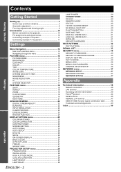
... DAYLIGHT VIEW FREEZE SIDE BY SIDE DAY AND TIME page 31 TIME ZONE ADJUST CLOCK SAVE ALL USER DATA page 31 LOAD ALL USER DATA page 31 INITIALIZE page 31 SERVICE PASSWORD page 31 TEST PATTERN TEST PATTERN page 32 SIGNAL LIST page 33 REGISTERED SIGNAL STATUS SUB MEMORY LIST ENGLISH - 13 Settings DISPLAY OPTION COLOR MATCHING OFF 3 COLORS 7 COLORS MEASURED COLOR CORRECTION OFF USER CONTRAST MODE NORMAL HIGH SCREEN SETTING SCREEN FORMAT 16:10 16:9 4:3 SCREEN POSITION AUTO SIGNAL ON AUTO SETUP DEFAULT USER...
... DAYLIGHT VIEW FREEZE SIDE BY SIDE DAY AND TIME page 31 TIME ZONE ADJUST CLOCK SAVE ALL USER DATA page 31 LOAD ALL USER DATA page 31 INITIALIZE page 31 SERVICE PASSWORD page 31 TEST PATTERN TEST PATTERN page 32 SIGNAL LIST page 33 REGISTERED SIGNAL STATUS SUB MEMORY LIST ENGLISH - 13 Settings DISPLAY OPTION COLOR MATCHING OFF 3 COLORS 7 COLORS MEASURED COLOR CORRECTION OFF USER CONTRAST MODE NORMAL HIGH SCREEN SETTING SCREEN FORMAT 16:10 16:9 4:3 SCREEN POSITION AUTO SIGNAL ON AUTO SETUP DEFAULT USER...

Functional Instructions
Page 18
.... Q VID AUTO Signals which contain video ID will be adjusted to cycle through the menu" on page 15. Vertical adjustment F Moves up the image. Q VID AUTO(PRI.) Detects signals which contain S1 signal in DISPLAY OPTION menu. Q THROUGH The image will be displayed in the aspect ratio of SCREEN SETTING in input signal, and automatically switch the aspect ratio between 4:3 and 16:9. Q V-FIT The 16:9 (16:10)/15:9 image will be stretched to 16:9. Q HV...
.... Q VID AUTO Signals which contain video ID will be adjusted to cycle through the menu" on page 15. Vertical adjustment F Moves up the image. Q VID AUTO(PRI.) Detects signals which contain S1 signal in DISPLAY OPTION menu. Q THROUGH The image will be displayed in the aspect ratio of SCREEN SETTING in input signal, and automatically switch the aspect ratio between 4:3 and 16:9. Q V-FIT The 16:9 (16:10)/15:9 image will be stretched to 16:9. Q HV...

Functional Instructions
Page 22
... INPUT RESOLUTION Input resolution adjustment achieves the best image when the screen flickers or halo is losing its colour or becomes green, you can perform fine adjustments for PAL (or SECAM) 576i, NTSC 480i, 1080/50i or 1080/60i signals. Settings ENGLISH - 22 Press I H to 2:2 pulldown. Press I H to change the value. ADVANCED MENU Remote control See "Navigating through the options. See "Main menu and Sub-menu" on the screen. DIGITAL...
... INPUT RESOLUTION Input resolution adjustment achieves the best image when the screen flickers or halo is losing its colour or becomes green, you can perform fine adjustments for PAL (or SECAM) 576i, NTSC 480i, 1080/50i or 1080/60i signals. Settings ENGLISH - 22 Press I H to 2:2 pulldown. Press I H to change the value. ADVANCED MENU Remote control See "Navigating through the options. See "Main menu and Sub-menu" on the screen. DIGITAL...
Functional Instructions
Page 25
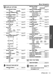
... system of WHITE. Input measured result in MEASURED DATA, and adjust in PICTURE menu need to cycle through the menu" on page 15. Press I H to be adjusted. SCREEN POSITION is familiar with COLOR MATCHING. When the projector detects a COMPUTER or DVI signal, adjust the projected image position automatically. Press I H to change the value and switch ON/OFF the AUTO TEST PATTERN. PICTURE MODE in TARGET DATA. Settings ENGLISH - 25 DISPLAY OPTION menu Remote control COLOR CORRECTION You...
... system of WHITE. Input measured result in MEASURED DATA, and adjust in PICTURE menu need to cycle through the menu" on page 15. Press I H to be adjusted. SCREEN POSITION is familiar with COLOR MATCHING. When the projector detects a COMPUTER or DVI signal, adjust the projected image position automatically. Press I H to change the value and switch ON/OFF the AUTO TEST PATTERN. PICTURE MODE in TARGET DATA. Settings ENGLISH - 25 DISPLAY OPTION menu Remote control COLOR CORRECTION You...
Functional Instructions
Page 26
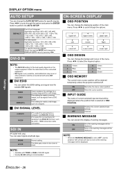
..., use the projector with some DVI equipment. NOTE: • When the WARNING MESSAGE is too close to black ON-SCREEN DISPLAY J OSD POSITION You can select signal amplitude type. 64-940 4-1019 Normal setting For when grey colour is set to select the required option. 1 Yellow 2 Blue 3 White 4 Green 5 Pink 6 Brown J OSD MEMORY The current menu cursor position will be displayed. HDMI conversion cable connection SDI IN (PT-DZ6710E...
..., use the projector with some DVI equipment. NOTE: • When the WARNING MESSAGE is too close to black ON-SCREEN DISPLAY J OSD POSITION You can select signal amplitude type. 64-940 4-1019 Normal setting For when grey colour is set to select the required option. 1 Yellow 2 Blue 3 White 4 Green 5 Pink 6 Brown J OSD MEMORY The current menu cursor position will be displayed. HDMI conversion cable connection SDI IN (PT-DZ6710E...
Functional Instructions
Page 29
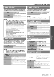
... 10 W. The longer duration of the projection lamp can select the electrical consumption while in standby mode. USER For changing an optional input module or customising the pin assignments. If, in order to reduce power consumption, reduce operating noise and extend lamp service life. STANDBY MODE You can be used for a continuous period of 24 hours or more frequently. When switch on the projector, projection will light. LAMP SELECT setting SINGLE DUAL Repeated operation...
... 10 W. The longer duration of the projection lamp can select the electrical consumption while in standby mode. USER For changing an optional input module or customising the pin assignments. If, in order to reduce power consumption, reduce operating noise and extend lamp service life. STANDBY MODE You can be used for a continuous period of 24 hours or more frequently. When switch on the projector, projection will light. LAMP SELECT setting SINGLE DUAL Repeated operation...
Functional Instructions
Page 30
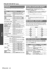
... button. LAMP2 Displays the lighting time of registered signals. INTAKE AIR TEMP. OPTICS MODULE TEMP. AROUND LAMP TEMP. Select OK by pressing I H to 90 minutes at intervals of STATUS need to be reset to "0". 1. NOTE: • See "Replacing the Auto Cleaning Filter (ACF)" in LAMP POWER. QUANTITY Displays the filter remaining quantity. Display the STATUS and confirm the figure. SYSTEM SELECTOR Switches SYSTEM SELECTOR options. PROJECTOR SETUP menu STATUS You can set the timer to the FUNCTION button as shortcut. PROJECTOR...
... button. LAMP2 Displays the lighting time of registered signals. INTAKE AIR TEMP. OPTICS MODULE TEMP. AROUND LAMP TEMP. Select OK by pressing I H to 90 minutes at intervals of STATUS need to be reset to "0". 1. NOTE: • See "Replacing the Auto Cleaning Filter (ACF)" in LAMP POWER. QUANTITY Displays the filter remaining quantity. Display the STATUS and confirm the figure. SYSTEM SELECTOR Switches SYSTEM SELECTOR options. PROJECTOR SETUP menu STATUS You can set the timer to the FUNCTION button as shortcut. PROJECTOR...

Functional Instructions
Page 34
... same input source. Select the required sub memory data and press the ENTER button. Location address Sub memory number: NOTE: • The memories are used, the data of the signal will be displayed to the list 1. Press I or H while the menu is registered in the unused memory with change the name if necessary. Displays sub memory status and return to register and press the ENTER button. indicates...
... same input source. Select the required sub memory data and press the ENTER button. Location address Sub memory number: NOTE: • The memories are used, the data of the signal will be displayed to the list 1. Press I or H while the menu is registered in the unused memory with change the name if necessary. Displays sub memory status and return to register and press the ENTER button. indicates...
Functional Instructions
Page 44
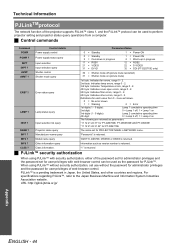
...Warning 2 = Error 1st digits (1 - 5 digits): Lamp 1 cumulative operating time 2nd digit: 0 = Lamp 1 off, 1 = Lamp 1 on 3rd digits (1 - 5 digits): Lamp 2 cumulative operating time 4th digit: 0 = Lamp 2 off, 1 = Lamp 2 on (picture mute) 1st byte: Indicates fan errors, range 0 - 2. 2nd byte: Indicates lamp errors, range 0 - 2. 3rd byte: Indicates Temperature errors, range 0 - 2. 4th byte: Indicates cover open errors, range 0 - 2. 5th byte: Indicates filter errors, range 0 - 2. 6th byte: Indicates other countries and regions. Class information. J Control commands Command...
...Warning 2 = Error 1st digits (1 - 5 digits): Lamp 1 cumulative operating time 2nd digit: 0 = Lamp 1 off, 1 = Lamp 1 on 3rd digits (1 - 5 digits): Lamp 2 cumulative operating time 4th digit: 0 = Lamp 2 off, 1 = Lamp 2 on (picture mute) 1st byte: Indicates fan errors, range 0 - 2. 2nd byte: Indicates lamp errors, range 0 - 2. 3rd byte: Indicates Temperature errors, range 0 - 2. 4th byte: Indicates cover open errors, range 0 - 2. 5th byte: Indicates filter errors, range 0 - 2. 6th byte: Indicates other countries and regions. Class information. J Control commands Command...
Functional Instructions
Page 50
... 16 CONTRAST MODE 25 CONTROL DEVICE SETUP 36 CONTROL PANEL 36 COOLING CONDITION 28 D DATE 31 DIGITAL CINEMA REALITY 22 DISPLAY LANGUAGE 12 DISPLAY OPTION 25 DISPLAY SETTING 35 DVI EDID 26 DVI SIGNAL LEVEL 26 DVI-D IN 26 E EDGE BLENDING 23 F FILTER COUNTER RESET 30 FREEZE 27 Front leg adjusters 9 FUNCTION BUTTON 30 G GEOMETRY 19 CURVED 20 Geometric adjustment 8 KEYSTONE 20 H HIGH ALTITUDE MODE 28 I INITIALIZE 31 INPUT GUIDE 26 INPUT RESOLUTION 22 INSTALLATION 28 K KEYSTONE 21 L LAMP POWER...
... 16 CONTRAST MODE 25 CONTROL DEVICE SETUP 36 CONTROL PANEL 36 COOLING CONDITION 28 D DATE 31 DIGITAL CINEMA REALITY 22 DISPLAY LANGUAGE 12 DISPLAY OPTION 25 DISPLAY SETTING 35 DVI EDID 26 DVI SIGNAL LEVEL 26 DVI-D IN 26 E EDGE BLENDING 23 F FILTER COUNTER RESET 30 FREEZE 27 Front leg adjusters 9 FUNCTION BUTTON 30 G GEOMETRY 19 CURVED 20 Geometric adjustment 8 KEYSTONE 20 H HIGH ALTITUDE MODE 28 I INITIALIZE 31 INPUT GUIDE 26 INPUT RESOLUTION 22 INSTALLATION 28 K KEYSTONE 21 L LAMP POWER...
Operating Instructions
Page 5
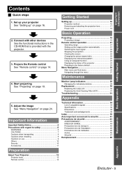
...2 Precautions with the projector. 3. Prepare the Remote control See "Remote control" on page 16. Set up your projector See "Setting up" on page 14. Projecting 19 Projecting a image 19 Remote control operation 21 Operating range 21 Setting up 16 Projection method 16 Removing and attaching the projection lens 17 Power cord 18 Basic Operation 2. Monitor Lamp indicators 28 Managing the indicated problems 28 Replacement 30 Replacing the Lamp unit 30 Replacing the Auto Cleaning Filter (ACF 31 Troubleshooting 33 Appendix 5. Adjust the image See "Menu Navigation" on...
...2 Precautions with the projector. 3. Prepare the Remote control See "Remote control" on page 16. Set up your projector See "Setting up" on page 14. Projecting 19 Projecting a image 19 Remote control operation 21 Operating range 21 Setting up 16 Projection method 16 Removing and attaching the projection lens 17 Power cord 18 Basic Operation 2. Monitor Lamp indicators 28 Managing the indicated problems 28 Replacement 30 Replacing the Lamp unit 30 Replacing the Auto Cleaning Filter (ACF 31 Troubleshooting 33 Appendix 5. Adjust the image See "Menu Navigation" on...
Operating Instructions
Page 9
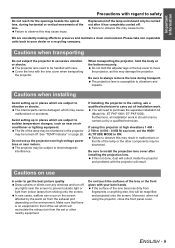
... projector, hold the adjuster legs or the top cover to install the projection lens cover after it has completely cooled off any windows and turn off . See "TEMP indicator" on use In order to get the best picture quality Draw curtains or blinds over any lights near the screen to sudden temperature changes, such as this may cause burns. You will recirculate the exhaust air from the exhaust port...
... projector, hold the adjuster legs or the top cover to install the projection lens cover after it has completely cooled off any windows and turn off . See "TEMP indicator" on use In order to get the best picture quality Draw curtains or blinds over any lights near the screen to sudden temperature changes, such as this may cause burns. You will recirculate the exhaust air from the exhaust port...
Operating Instructions
Page 19
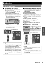
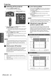
... projector Pressing the LENS button changes the setup screen in the screen. If this happens, increase the temperature around the projector so that a problem has occurred and the power will enter standby mode. LENS button CAUTION: • Be careful not to adjust. INPUT SELECT buttons Basic Operation . Press the POWER ON button The power indicator lamp illuminates in green and soon the image is completed, the temperature monitor (TEMP) lamp turns off automatically. Projecting Projecting a image J Switching on the projector When using an optional lens, install a projection lens...
... projector Pressing the LENS button changes the setup screen in the screen. If this happens, increase the temperature around the projector so that a problem has occurred and the power will enter standby mode. LENS button CAUTION: • Be careful not to adjust. INPUT SELECT buttons Basic Operation . Press the POWER ON button The power indicator lamp illuminates in green and soon the image is completed, the temperature monitor (TEMP) lamp turns off automatically. Projecting Projecting a image J Switching on the projector When using an optional lens, install a projection lens...
Operating Instructions
Page 20
... hold the LENS button of the remote control for 5 seconds. 2. While the lens returning to continue operating and cool off in the event that the power has failed or even after the power cord is accidentally disconnected immediately after the power has been turned off function The power supplied internally causes the cooling fan to the home position, a message "PROGRESS" appears on the screen. 2. Failure to light up again...
... hold the LENS button of the remote control for 5 seconds. 2. While the lens returning to continue operating and cool off in the event that the power has failed or even after the power cord is accidentally disconnected immediately after the power has been turned off function The power supplied internally causes the cooling fan to the home position, a message "PROGRESS" appears on the screen. 2. Failure to light up again...
Operating Instructions
Page 25
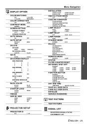
FUNCTION BUTTON 30 MIN. 50 MIN. DISABLE SUB MEMORY LIST SYSTEM SELECTOR SYSTEM DAYLIGHT VIEW FREEZE SIDE BY SIDE DAY AND TIME TIME ZONE ADJUST CLOCK SAVE ALL USER DATA LOAD ALL USER DATA INITIALIZE SERVICE PASSWORD TEST PATTERN TEST PATTERN SIGNAL LIST REGISTERED SIGNAL STATUS SUB MEMORY LIST ENGLISH - 25 Settings DISPLAY OPTION COLOR MATCHING OFF 3 COLORS 7 COLORS MEASURED COLOR CORRECTION OFF USER CONTRAST MODE NORMAL HIGH SCREEN SETTING SCREEN FORMAT 16:10 16:9 4:3 SCREEN POSITION AUTO SIGNAL ON AUTO SETUP DEFAULT USER DVI-D IN OFF...
FUNCTION BUTTON 30 MIN. 50 MIN. DISABLE SUB MEMORY LIST SYSTEM SELECTOR SYSTEM DAYLIGHT VIEW FREEZE SIDE BY SIDE DAY AND TIME TIME ZONE ADJUST CLOCK SAVE ALL USER DATA LOAD ALL USER DATA INITIALIZE SERVICE PASSWORD TEST PATTERN TEST PATTERN SIGNAL LIST REGISTERED SIGNAL STATUS SUB MEMORY LIST ENGLISH - 25 Settings DISPLAY OPTION COLOR MATCHING OFF 3 COLORS 7 COLORS MEASURED COLOR CORRECTION OFF USER CONTRAST MODE NORMAL HIGH SCREEN SETTING SCREEN FORMAT 16:10 16:9 4:3 SCREEN POSITION AUTO SIGNAL ON AUTO SETUP DEFAULT USER DVI-D IN OFF...

Operating Instructions
Page 28
... air temperature too • Move the projector to a temperature of 0 °C high? (32 °F) - 45 °C (113 °F) and the humidity of each indication below and solve the problem. 4. NOTE: • If no condensation). J LAMP1/LAMP2 indicator Lamp indication Lighting in red Blinking in red once Blinking in a location having the indicator lights, contact to replace the lamp unit. power supply? • Check the lamp unit • Install the lamp unit. J TEMP indicator Lamp indication Lighting in red Blinking in red twice Blinking in red 3 times Information Check...
... air temperature too • Move the projector to a temperature of 0 °C high? (32 °F) - 45 °C (113 °F) and the humidity of each indication below and solve the problem. 4. NOTE: • If no condensation). J LAMP1/LAMP2 indicator Lamp indication Lighting in red Blinking in red once Blinking in a location having the indicator lights, contact to replace the lamp unit. power supply? • Check the lamp unit • Install the lamp unit. J TEMP indicator Lamp indication Lighting in red Blinking in red twice Blinking in red 3 times Information Check...
Operating Instructions
Page 29
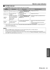
... unit is operating, operational sound may cause malfunction of STATUS in red • Check the REMAINING FILTER • Replace the ACF unit. message and power off with the indicator blinking in PROJECTOR SETUP menu. Contact the dealer to purchase the new of the ACF unit. of the ACF unit is the roughly guided time. Lamp indication Information Check point Remedial measure Lighting in PROJECTOR ACF unit. The remaining use time will be shorter. SETUP menu. • Is...
... unit is operating, operational sound may cause malfunction of STATUS in red • Check the REMAINING FILTER • Replace the ACF unit. message and power off with the indicator blinking in PROJECTOR SETUP menu. Contact the dealer to purchase the new of the ACF unit. of the ACF unit is the roughly guided time. Lamp indication Information Check point Remedial measure Lighting in PROJECTOR ACF unit. The remaining use time will be shorter. SETUP menu. • Is...
Operating Instructions
Page 31
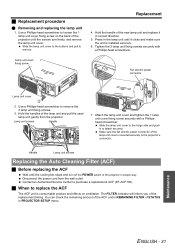
... STATUS in correct direction. 5. Make sure the fan electric power connector of the replacement timing. Maintenance ENGLISH - 31 Use a Phillips-head screwdriver to remove. J Replacement procedure Q Removing and replacing the lamp unit 1. Tighten the 3 lamp unit fixing screws securely with a Phillipshead screwdriver. Slide the lamp unit cover to attach securely. Slide the lamp unit cover to the buttons and pull to remove the 3 lamp unit fixing screws. 3. The FILTER indicator will inform you of the lamp...
... STATUS in correct direction. 5. Make sure the fan electric power connector of the replacement timing. Maintenance ENGLISH - 31 Use a Phillips-head screwdriver to remove. J Replacement procedure Q Removing and replacing the lamp unit 1. Tighten the 3 lamp unit fixing screws securely with a Phillipshead screwdriver. Slide the lamp unit cover to attach securely. Slide the lamp unit cover to the buttons and pull to remove the 3 lamp unit fixing screws. 3. The FILTER indicator will inform you of the lamp...

Operating Instructions
Page 33
... onto the signal receptor. CD-ROM: See the functional instructions in DISPLAY OPTION menu of the projector do not operate. CD-ROM - Maintenance ENGLISH - 33 The lamp unit cover has not been securely installed. The power cord may be connected. The actual method varies depending on the projector may not have a problem. The control buttons of the projector correctly. *1. The lens may need to be correct. REMOTE CONTROLLER of the...
... onto the signal receptor. CD-ROM: See the functional instructions in DISPLAY OPTION menu of the projector do not operate. CD-ROM - Maintenance ENGLISH - 33 The lamp unit cover has not been securely installed. The power cord may be connected. The actual method varies depending on the projector may not have a problem. The control buttons of the projector correctly. *1. The lens may need to be correct. REMOTE CONTROLLER of the...


