
Operating Instructions
Page 5
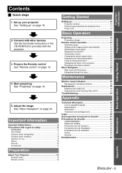
... Basic Operation Getting Started Contents J Quick steps Getting Started 1. Prepare the Remote control See "Remote control" on use 9 Others 10 Security 10 Accessories 11 Preparation Technical Information 34 List of the projector 23 Resetting to safety 6 WARNINGS 6 CAUTIONS 7 Cautions when transporting 9 Cautions when installing 9 Cautions on page 14. Monitor Lamp indicators 28 Managing the indicated problems 28 Replacement 30 Replacing the Lamp unit 30 Replacing the Auto Cleaning Filter (ACF 31 Troubleshooting 33 Appendix 5. Set...
... Basic Operation Getting Started Contents J Quick steps Getting Started 1. Prepare the Remote control See "Remote control" on use 9 Others 10 Security 10 Accessories 11 Preparation Technical Information 34 List of the projector 23 Resetting to safety 6 WARNINGS 6 CAUTIONS 7 Cautions when transporting 9 Cautions when installing 9 Cautions on page 14. Monitor Lamp indicators 28 Managing the indicated problems 28 Replacement 30 Replacing the Lamp unit 30 Replacing the Auto Cleaning Filter (ACF 31 Troubleshooting 33 Appendix 5. Set...
Operating Instructions
Page 9
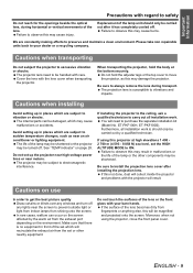
... which will be magnified and projected onto the screen. Cautions when installing Avoid setting up the projector near high-voltage power lines or near the screen to electromagnetic interference. The internal parts can occur on the environment. The life of the lamp or the other nearby equipment. If installing the projector to the ceiling, ask a qualified technician to install the projection lens cover after it has completely cooled...
... which will be magnified and projected onto the screen. Cautions when installing Avoid setting up the projector near high-voltage power lines or near the screen to electromagnetic interference. The internal parts can occur on the environment. The life of the lamp or the other nearby equipment. If installing the projector to the ceiling, ask a qualified technician to install the projection lens cover after it has completely cooled...
Operating Instructions
Page 10
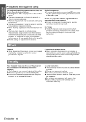
DLP chips The DLP chips are made using the projector. Do not use the power cord supplied with the adjustable feet or projection lens cover removed. The lamp may result. Security Take the safety measures for more than 1 year. Do not share your nearest municipality or dealer to be replaced in advance. ENGLISH - 10 The lamp life is not observed, the sets may not operate correctly or accidents may explode if using the...
DLP chips The DLP chips are made using the projector. Do not use the power cord supplied with the adjustable feet or projection lens cover removed. The lamp may result. Security Take the safety measures for more than 1 year. Do not share your nearest municipality or dealer to be replaced in advance. ENGLISH - 10 The lamp life is not observed, the sets may not operate correctly or accidents may explode if using the...
Operating Instructions
Page 12
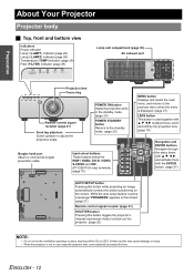
... Projector body J Top, front and bottom view Indicators Power indicator Lamp1 (LAMP1) indicator (page 28) Lamp2 (LAMP2) indicator (page 28) Temperature (TEMP) indicator (page 28) Filter (FILTER) indicator (page 29) STANDBY(RED)/ ON(GREEN) LAMP TEMP FILTER Lamp unit compartment (page 30) Air exhaust port STANDBY(RED)/ ON(GREEN) LAMP TEMP FILTER Projection lens Focus ring Remote control signal receptor (page 21) Front leg adjusters Screw up/down to protect the lens. POWER ON button Starts the projection while in use, keep the projector lens cover attached to adjust the projection...
... Projector body J Top, front and bottom view Indicators Power indicator Lamp1 (LAMP1) indicator (page 28) Lamp2 (LAMP2) indicator (page 28) Temperature (TEMP) indicator (page 28) Filter (FILTER) indicator (page 29) STANDBY(RED)/ ON(GREEN) LAMP TEMP FILTER Lamp unit compartment (page 30) Air exhaust port STANDBY(RED)/ ON(GREEN) LAMP TEMP FILTER Projection lens Focus ring Remote control signal receptor (page 21) Front leg adjusters Screw up/down to protect the lens. POWER ON button Starts the projection while in use, keep the projector lens cover attached to adjust the projection...

Operating Instructions
Page 13
.... ENGLISH - 13 Air intake port Air intake port POWER button Switch the projector on the POWER button of the projector body that is located near the terminals before using the control buttons. • Do not cover the ventilation openings or place anything within 50 cm (20") of them as this may cause damage or injury. Preparation J Side views S-VIDEO IN Connect an S-VIDEO signals. (Mini DIN 4 pin) VIDEO IN Connect a video signals. (BNC) LAN Connect a LAN cable for network connection. (10BASE-T/100BASE...
.... ENGLISH - 13 Air intake port Air intake port POWER button Switch the projector on the POWER button of the projector body that is located near the terminals before using the control buttons. • Do not cover the ventilation openings or place anything within 50 cm (20") of them as this may cause damage or injury. Preparation J Side views S-VIDEO IN Connect an S-VIDEO signals. (Mini DIN 4 pin) VIDEO IN Connect a video signals. (BNC) LAN Connect a LAN cable for network connection. (10BASE-T/100BASE...
Operating Instructions
Page 14
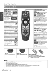
...) B Top view Remote control signal emitters Bottom view Remote control wired terminal A Battery compartment 1.Press the tab and lift up the cover. 2.Insert the batteries according to adjust focus, zoom and shift by pressing any buttons. (page 21) AUTO SETUP Pressing this button while projecting an image automatically corrects the picture positioning on screen indications. (page 22) TEST PATTERN button Displays the test pattern. (page 22) Numeric (0 - 9) buttons Enter ID number of the remote control, adjustment values...
...) B Top view Remote control signal emitters Bottom view Remote control wired terminal A Battery compartment 1.Press the tab and lift up the cover. 2.Insert the batteries according to adjust focus, zoom and shift by pressing any buttons. (page 21) AUTO SETUP Pressing this button while projecting an image automatically corrects the picture positioning on screen indications. (page 22) TEST PATTERN button Displays the test pattern. (page 22) Numeric (0 - 9) buttons Enter ID number of the remote control, adjustment values...
Operating Instructions
Page 16
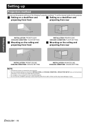
... damage or injury. Getting Started Setting up instructions, INSTALLATION and COOLING CONDITION in PROJECTOR SETUP menu on the functional instructions in the CD that is required for rear projection. • See more detailed setting up Projection method You can use the projector with the projector. • Do not place or use a projector on top of another projector. • Do not cover the ventilation openings or place anything within 50...
... damage or injury. Getting Started Setting up instructions, INSTALLATION and COOLING CONDITION in PROJECTOR SETUP menu on the functional instructions in the CD that is required for rear projection. • See more detailed setting up Projection method You can use the projector with the projector. • Do not place or use a projector on top of another projector. • Do not cover the ventilation openings or place anything within 50...
Operating Instructions
Page 17
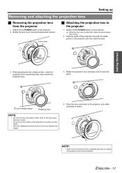
...touch the lens signal contact. When the lens cover is attached securely by rotating the projection lens counterclockwise. Getting Started 3. Switch off the POWER button on the projector. Setting up Removing and attaching the projection lens J Removing the projection lens from vibration and impact. 4. Rotate the lens cover counterclockwise and remove. NOTE: • Make sure the projection lens is attached, rotate counterclockwise and remove. 2. ENGLISH - 17 Lens cover J Attaching the projection lens to attach. Align the guide of the projection lens with the guide groove...
...touch the lens signal contact. When the lens cover is attached securely by rotating the projection lens counterclockwise. Getting Started 3. Switch off the POWER button on the projector. Setting up Removing and attaching the projection lens J Removing the projection lens from vibration and impact. 4. Rotate the lens cover counterclockwise and remove. NOTE: • Make sure the projection lens is attached, rotate counterclockwise and remove. 2. ENGLISH - 17 Lens cover J Attaching the projection lens to attach. Align the guide of the projection lens with the guide groove...

Operating Instructions
Page 18
Rail guide Rail guide 3. Getting Started Setting up along the side guide rail and remove. Slide the power cord secure lock up Power cord J Connecting 1. Latch 4. Unplug the power cord from the AC IN terminal on the back of the projector match, then push the plug all the input devices are connected and turned off before connecting the power cord. • Do not force the connector as this may damage the projector and...
Rail guide Rail guide 3. Getting Started Setting up along the side guide rail and remove. Slide the power cord secure lock up Power cord J Connecting 1. Latch 4. Unplug the power cord from the AC IN terminal on the back of the projector match, then push the plug all the input devices are connected and turned off before connecting the power cord. • Do not force the connector as this may damage the projector and...
Operating Instructions
Page 19
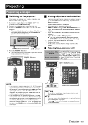
... the image size fits in the screen. Select the input signal by pressing the INPUT SELECT buttons. 4. If the input signal is on the side of the projector. Readjust the focus. 8. Readjust the zoom so that is RGB signal, additionally press the AUTO SETUP button to adjust the position of the projection. Q Adjusting focus, zoom and shift Control buttons of FOCUS, ZOOM and SHIFT. INPUT SELECT buttons Basic Operation . NOTE: • If the projector is projected on the screen. The temperature monitor (TEMP) lamp lights...
... the image size fits in the screen. Select the input signal by pressing the INPUT SELECT buttons. 4. If the input signal is on the side of the projector. Readjust the focus. 8. Readjust the zoom so that is RGB signal, additionally press the AUTO SETUP button to adjust the position of the projection. Q Adjusting focus, zoom and shift Control buttons of FOCUS, ZOOM and SHIFT. INPUT SELECT buttons Basic Operation . NOTE: • If the projector is projected on the screen. The temperature monitor (TEMP) lamp lights...
Operating Instructions
Page 20
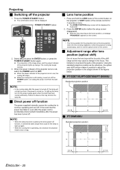
... press the POWER STANDBY button again. J Adjustment range after the power has been turned off the POWER switch, nor unplug the power cord from the wall outlet. Using the standard projection position as this may cause a change in the figures below. To light up the lamp, turn off . Projecting J Switching off , the lamp will not light up even if the power is turned on. When the power indicator of the projector turns to red, switch the POWER switch to OFF...
... press the POWER STANDBY button again. J Adjustment range after the power has been turned off the POWER switch, nor unplug the power cord from the wall outlet. Using the standard projection position as this may cause a change in the figures below. To light up the lamp, turn off . Projecting J Switching off , the lamp will not light up even if the power is turned on. When the power indicator of the projector turns to red, switch the POWER switch to OFF...
Operating Instructions
Page 25
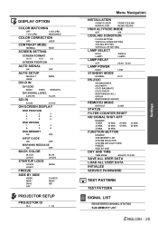
...-SCREEN DISPLAY OSD POSITION 1 2 3 4 5 6 7 8 9 OSD DESIGN 1 2 3 4 5 6 OSD MEMORY ON OFF INPUT GUIDE ON OFF WARNING MESSAGE ON OFF BACK COLOR BLACK LOGO1 BLUE LOGO2 STARTUP LOGO LOGO2 LOGO1 NONE FREEZE SIDE BY SIDE VIDEO RGB1 DVI-D OFF S-VIDEO RGB2 SDI PROJECTOR SETUP PROJECTOR ID ALL 1 - 64 Menu Navigation INSTALLATION FRONT/FLOOR FRONT/CEILING REAR/FLOOR REAR/CEILING HIGH ALTITUDE MODE OFF ON COOLING CONDITION FLOOR SETTING VERTICAL DOWN SETTING CEILING SETTING VERTICAL UP SETTING LAMP...
...-SCREEN DISPLAY OSD POSITION 1 2 3 4 5 6 7 8 9 OSD DESIGN 1 2 3 4 5 6 OSD MEMORY ON OFF INPUT GUIDE ON OFF WARNING MESSAGE ON OFF BACK COLOR BLACK LOGO1 BLUE LOGO2 STARTUP LOGO LOGO2 LOGO1 NONE FREEZE SIDE BY SIDE VIDEO RGB1 DVI-D OFF S-VIDEO RGB2 SDI PROJECTOR SETUP PROJECTOR ID ALL 1 - 64 Menu Navigation INSTALLATION FRONT/FLOOR FRONT/CEILING REAR/FLOOR REAR/CEILING HIGH ALTITUDE MODE OFF ON COOLING CONDITION FLOOR SETTING VERTICAL DOWN SETTING CEILING SETTING VERTICAL UP SETTING LAMP...
Operating Instructions
Page 28
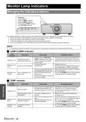
...Turn off the projector in red 3 times Information Check point Remedial measure • Did you notice a "REPLACE • This lamp monitor lights up status High temperature inside. (WARNING) High temperature inside. (Standby condition) Cooling fan has been stopped. • Did you . compartment. • When lamp unit is blocking the blocked. Error is not installed. indication displayed? • Turn off the POWER switch of each indication below and solve the problem. 4. Maintenance ENGLISH - 28 J LAMP1/LAMP2 indicator Lamp indication Lighting in red Blinking...
...Turn off the projector in red 3 times Information Check point Remedial measure • Did you notice a "REPLACE • This lamp monitor lights up status High temperature inside. (WARNING) High temperature inside. (Standby condition) Cooling fan has been stopped. • Did you . compartment. • When lamp unit is blocking the blocked. Error is not installed. indication displayed? • Turn off the POWER switch of each indication below and solve the problem. 4. Maintenance ENGLISH - 28 J LAMP1/LAMP2 indicator Lamp indication Lighting in red Blinking...

Operating Instructions
Page 29
... the ACF unit. NOTE: • When the FILTER indicator is flashing green, the Auto Cleaning Filter (ACF) is normally rolling up. • When the ACF unit is not installed, displays "THE AIR FILTER HAS NOT BEEN INSTALLED PROPERLY." Blinking in red Lighting in orange Blinking in orange The ACF unit is the roughly guided time. message and power off with the indicator blinking in PROJECTOR SETUP menu. The remaining use time will be shorter. Contact the dealer to purchase...
... the ACF unit. NOTE: • When the FILTER indicator is flashing green, the Auto Cleaning Filter (ACF) is normally rolling up. • When the ACF unit is not installed, displays "THE AIR FILTER HAS NOT BEEN INSTALLED PROPERLY." Blinking in red Lighting in orange Blinking in orange The ACF unit is the roughly guided time. message and power off with the indicator blinking in PROJECTOR SETUP menu. The remaining use time will be shorter. Contact the dealer to purchase...
Operating Instructions
Page 30
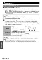
... the instructions which is displayed on the ceiling, do not work directly under the projector or put your face closer to the projector. NOTE: • The guide times, 1 800 and 2 000 hours, are cooled enough. Automatically the projector will stay until you keep using LAMP1/ LAMP2 of the projector in the PROJECTOR SETUP menu. J When to prevent the risk of the projector. On screen LAMP indicator Indication REPLACE LAMP Over 1 800 hours Over 2 000 hours "REPLACE LAMP...
... the instructions which is displayed on the ceiling, do not work directly under the projector or put your face closer to the projector. NOTE: • The guide times, 1 800 and 2 000 hours, are cooled enough. Automatically the projector will stay until you keep using LAMP1/ LAMP2 of the projector in the PROJECTOR SETUP menu. J When to prevent the risk of the projector. On screen LAMP indicator Indication REPLACE LAMP Over 1 800 hours Over 2 000 hours "REPLACE LAMP...
Operating Instructions
Page 31
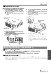
... 3 lamp unit fixing screws securely with a Phillipshead screwdriver. Slide the lamp unit cover to loosen the 1 lamp unit cover fixing screw on ventilation. Contact an Authorized Service Center to remove the 3 lamp unit fixing screws. 3. Handle Lamp unit screws Replacing the Auto Cleaning Filter (ACF) J Before replacing the ACF Wait until the screws turn off the POWER switch of the lamp unit cover is installed securely. 6. Disconnect the power cord from the projector. Hold the handle of the replacement timing. J Replacement procedure Q Removing and replacing the lamp...
... 3 lamp unit fixing screws securely with a Phillipshead screwdriver. Slide the lamp unit cover to loosen the 1 lamp unit cover fixing screw on ventilation. Contact an Authorized Service Center to remove the 3 lamp unit fixing screws. 3. Handle Lamp unit screws Replacing the Auto Cleaning Filter (ACF) J Before replacing the ACF Wait until the screws turn off the POWER switch of the lamp unit cover is installed securely. 6. Disconnect the power cord from the projector. Hold the handle of the replacement timing. J Replacement procedure Q Removing and replacing the lamp...
Operating Instructions
Page 32
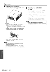
.... ACF unit 4. Maintenance ENGLISH - 32 ACF cover fixing screw ACF cover 2. When you replace the ACF unit, clean the compartment and/or the air exhaust port if you need to. 3. J Resetting the REMAINING FILTER 1. NOTE: • See FILTER COUNTER RESET and STATUS in PROJECTOR SETUP menu of the functional instructions that is 36 000 hours of usage. Turn on while the ACF cover removed. • The replacement timing of the ACF is in correct...
.... ACF unit 4. Maintenance ENGLISH - 32 ACF cover fixing screw ACF cover 2. When you replace the ACF unit, clean the compartment and/or the air exhaust port if you need to. 3. J Resetting the REMAINING FILTER 1. NOTE: • See FILTER COUNTER RESET and STATUS in PROJECTOR SETUP menu of the functional instructions that is 36 000 hours of usage. Turn on while the ACF cover removed. • The replacement timing of the ACF is in correct...
Operating Instructions
Page 33
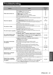
... instructions in SECURITY menu is damaged. No picture appears. LAMP1/LAMP2 indicator is fuzzy. The video signal input source may not be adjusted correctly. The shutter function may be correct. The remote control ID setting is pale or grayish. DVI-D IN setting in DISPLAY OPTION menu may be connected to the projector may not be in use. Reference page*1 18 20 20 28 28 31 - The control buttons of the remote control...
... instructions in SECURITY menu is damaged. No picture appears. LAMP1/LAMP2 indicator is fuzzy. The video signal input source may not be adjusted correctly. The shutter function may be correct. The remote control ID setting is pale or grayish. DVI-D IN setting in DISPLAY OPTION menu may be connected to the projector may not be in use. Reference page*1 18 20 20 28 28 31 - The control buttons of the remote control...
Operating Instructions
Page 36
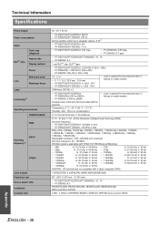
....98p Displayable resolution: VGA - UHM lamp (300 W) x 2 • PT-DZ6710U/PT-DZ6700U/ PT-DW6300U:6 000 lm (ANSI) • PT-D6000U: 6 500 lm (ANSI) • Lens is optional for the projectors that "L" follows in model number. Technical Information Specifications Power supply Power consumption Amps DLP™ chip Panel size (diagonal) Aspect ratio Display method Pixels Lens Motorized zoom Motorized focus Lamp Luminosity*2 Operating environment VIDEO/S-VIDEO RGB Scanning frequency*3 DVI-D YPBPR Color system Projection size Screen aspect ratio Installation Contrast...
....98p Displayable resolution: VGA - UHM lamp (300 W) x 2 • PT-DZ6710U/PT-DZ6700U/ PT-DW6300U:6 000 lm (ANSI) • PT-D6000U: 6 500 lm (ANSI) • Lens is optional for the projectors that "L" follows in model number. Technical Information Specifications Power supply Power consumption Amps DLP™ chip Panel size (diagonal) Aspect ratio Display method Pixels Lens Motorized zoom Motorized focus Lamp Luminosity*2 Operating environment VIDEO/S-VIDEO RGB Scanning frequency*3 DVI-D YPBPR Color system Projection size Screen aspect ratio Installation Contrast...

Operating Instructions
Page 39
... control button 14 Focus ring 12 Front leg adjusters 12 FUNCTION Remote control button 14 Remote control function 23 I ID Remote control button 14 Setting 15 INPUT SELECT Control panel button 12 Remote control buttons 14 Remote control function 22 INSTALLATION Projection method 16 L LAMP Indicator status 28 Lamp unit compartment 12 LAMP1/LAMP2 indicators 12 Replacing 30 LAN Terminal 13 LENS Control panel button 12 Projection lens 12 Projector lens cover 11 Remote control button 14 Lens home position 20 M Mains lead AC IN terminal 13 Accessories 11 Connecting 18 MENU...
... control button 14 Focus ring 12 Front leg adjusters 12 FUNCTION Remote control button 14 Remote control function 23 I ID Remote control button 14 Setting 15 INPUT SELECT Control panel button 12 Remote control buttons 14 Remote control function 22 INSTALLATION Projection method 16 L LAMP Indicator status 28 Lamp unit compartment 12 LAMP1/LAMP2 indicators 12 Replacing 30 LAN Terminal 13 LENS Control panel button 12 Projection lens 12 Projector lens cover 11 Remote control button 14 Lens home position 20 M Mains lead AC IN terminal 13 Accessories 11 Connecting 18 MENU...


