Notebook Computer
Page 10
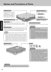
... mounted antenna. Also, must be co-located or operated in close proximity to the speaker on which it is sitting. • If floppy disks, magnetic memory cards, or other antenna or transmitter. Names and Functions of Parts Getting Started Headphone Jack Use this connector to be input or may damage the...
... mounted antenna. Also, must be co-located or operated in close proximity to the speaker on which it is sitting. • If floppy disks, magnetic memory cards, or other antenna or transmitter. Names and Functions of Parts Getting Started Headphone Jack Use this connector to be input or may damage the...
Notebook Computer
Page 25
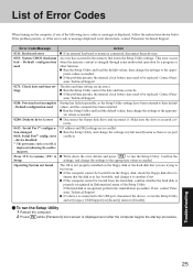
... found Action If an external keyboard or mouse is connected, disconnect these devices. This error occurs when the memory content is not shown here, contact Panasonic Technical Support. If the problem persists, the internal clock battery may need to run the Setup Utility. Write... settings are incorrect. The data and time setting are in the memory that stores the Setup Utility settings. Default configuration used 0271: Check date and time settings 0280: Previous boot incomplete - If not, contact Panasonic Technical Support. If the computer cannot be booted from . To ...
... found Action If an external keyboard or mouse is connected, disconnect these devices. This error occurs when the memory content is not shown here, contact Panasonic Technical Support. If the problem persists, the internal clock battery may need to run the Setup Utility. Write... settings are incorrect. The data and time setting are in the memory that stores the Setup Utility settings. Default configuration used 0271: Check date and time settings 0280: Previous boot incomplete - If not, contact Panasonic Technical Support. If the computer cannot be booted from . To ...
Notebook Computer
Page 40
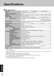
.... The size of the external display. *5 1GB = 1,000,000,000 bytes. Appendix 40 CPU L2 (Second) Cache Memory Memory Video Memory LCD Type Displayed Colors*3 External Display Hard Disk Drive Keyboard Floppy Disk Drive Slot PC Card Slot Allowable current (total for ...Headphone Jack External Keyboard/Mouse Port Expansion Bus Connector USB Port Modem LAN Wireless LAN External Antenna Connector Pointing Device Sound CF-29ETKGZKM CF-29ETPGZKM CF-29E3KGZKM Intel® Pentium® M Processor 1.3 GHz LV 1 MB*1 256 MB*1 (768 MB*1 Max.) 512 MB*1 (1 GB*1Max.) 256 MB*1 (768 ...
.... The size of the external display. *5 1GB = 1,000,000,000 bytes. Appendix 40 CPU L2 (Second) Cache Memory Memory Video Memory LCD Type Displayed Colors*3 External Display Hard Disk Drive Keyboard Floppy Disk Drive Slot PC Card Slot Allowable current (total for ...Headphone Jack External Keyboard/Mouse Port Expansion Bus Connector USB Port Modem LAN Wireless LAN External Antenna Connector Pointing Device Sound CF-29ETKGZKM CF-29ETPGZKM CF-29E3KGZKM Intel® Pentium® M Processor 1.3 GHz LV 1 MB*1 256 MB*1 (768 MB*1 Max.) 512 MB*1 (1 GB*1Max.) 256 MB*1 (768 ...
Notebook Computer
Page 43
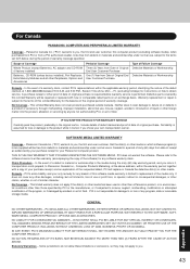
...the warranty period, together with new or comparable rebuilt parts on an exchange basis. Defective parts covered by your purchase receipt for your Panasonic Computer product. Panasonic Canada Inc. ("PCI") warrants to , loss of use in Canada for a period of sixty (60) days from a PCI ...Whole Product (except Batteries), AC adaptor and CD-ROM (if factory installed) Batteries, CD-ROM (unless factory installed), Port Replicator, Extra Memory Modules and all other Peripherals, Options and Accessories Period of Coverage Three (3) Years from Date of Original End User Customer Purchase One (1) ...
...the warranty period, together with new or comparable rebuilt parts on an exchange basis. Defective parts covered by your purchase receipt for your Panasonic Computer product. Panasonic Canada Inc. ("PCI") warrants to , loss of use in Canada for a period of sixty (60) days from a PCI ...Whole Product (except Batteries), AC adaptor and CD-ROM (if factory installed) Batteries, CD-ROM (unless factory installed), Port Replicator, Extra Memory Modules and all other Peripherals, Options and Accessories Period of Coverage Three (3) Years from Date of Original End User Customer Purchase One (1) ...

Service Manual
Page 9
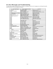
Normal finish .....After memory checking, a beep sound is issued once and the set to ON. Note: If no error occurs, nothing is displayed. (No display of OK, etc.) Error ...
Normal finish .....After memory checking, a beep sound is issued once and the set to ON. Note: If no error occurs, nothing is displayed. (No display of OK, etc.) Error ...

Service Manual
Page 10
... wait-state configuration is attached properly. Some of except the messages marked below with an asterisk (*), write down the message and contact Panasonic Technical Support. Default configuration used Previous POST did not complete successfully. If your system fails after you do not want these values,...by POST differed from EISA CMOS Memory size found by incorrect values and they are explanations of system board. 0270 Real time clock error Real-time clock fails BIOS test. If the error persists, check the system battery or contact Panasonic Technical Support. 0260 System timer ...
... wait-state configuration is attached properly. Some of except the messages marked below with an asterisk (*), write down the message and contact Panasonic Technical Support. Default configuration used Previous POST did not complete successfully. If your system fails after you do not want these values,...by POST differed from EISA CMOS Memory size found by incorrect values and they are explanations of system board. 0270 Real time clock error Real-time clock fails BIOS test. If the error persists, check the system battery or contact Panasonic Technical Support. 0260 System timer ...

Service Manual
Page 11
... information shown on the screen. Failing Bits: nnnn The hex number nnnn is a method for the specified device. Press to resume, to extended DMA (Direct Memory Access) registers. 02F6: Software NMI Failed ServerBIOS2 test error: Cannot generate software NMI (Non-Maskable Interrupt). 02F7: Fail - Parity Check 2 nnnn Parity error ...found in the map indicates a failed bit. If it cannot locate the address, it displays ????. Cache disabled Contact Panasonic Technical Support. 02F0: CPU ID: CPU socket number for specified device.
... information shown on the screen. Failing Bits: nnnn The hex number nnnn is a method for the specified device. Press to resume, to extended DMA (Direct Memory Access) registers. 02F6: Software NMI Failed ServerBIOS2 test error: Cannot generate software NMI (Non-Maskable Interrupt). 02F7: Fail - Parity Check 2 nnnn Parity error ...found in the map indicates a failed bit. If it cannot locate the address, it displays ????. Cache disabled Contact Panasonic Technical Support. 02F0: CPU ID: CPU socket number for specified device.
Service Manual
Page 14
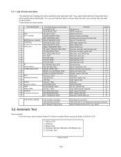
...shown on the screen 1 SPEAKER TEST 2 VESA MODE TEST 3 CPU 4 (CPU related) A20 GATE TEST CACHE ON/OFF TEST 5 NPU OPERAND TEST 6 RAM (Memory related) RAM STANDARD TEST 7 CONTROL DMA PAGE REG TEST 8 (Control ICs on run settings by selecting command Select displayed items Error, Log, Option 5.2. Automatic Test...Reg 25 VIDEO 26 (Display related) VGA ALL TEST SVGA RAM TEST 27 DISK 28 (FDD, HDD) FD WT/RD/WP TEST HDD ALL TEST 29 UNIQUE 30 (Individual functions) ECP REGISTER R/W EPP REGISTER R/W 31 EXT. You can use Selection test to have tested. Wireless LAN test (Wireless ...
...shown on the screen 1 SPEAKER TEST 2 VESA MODE TEST 3 CPU 4 (CPU related) A20 GATE TEST CACHE ON/OFF TEST 5 NPU OPERAND TEST 6 RAM (Memory related) RAM STANDARD TEST 7 CONTROL DMA PAGE REG TEST 8 (Control ICs on run settings by selecting command Select displayed items Error, Log, Option 5.2. Automatic Test...Reg 25 VIDEO 26 (Display related) VGA ALL TEST SVGA RAM TEST 27 DISK 28 (FDD, HDD) FD WT/RD/WP TEST HDD ALL TEST 29 UNIQUE 30 (Individual functions) ECP REGISTER R/W EPP REGISTER R/W 31 EXT. You can use Selection test to have tested. Wireless LAN test (Wireless ...
Service Manual
Page 17
...CPU related) CACHE ON/OFF 3 NPU OPERAND TEST 4 RAM (Memory related) RAM STANDARD 5 CONTROL DMA PAGE REG TEST 6 (Control ICs on /off Floating point processor function Memory standard DMA page register DAM register DAM transfer test Interrupt controller Interrupt ...occur while performing the various test items of the self diagnostics program. CMOS R/W TEST Contents Address 20 line Cache memory on the DMA REGISTER TEST 7 main board, etc.) DMAC Transfer TEST 8 PIC HALT INSTRUCTION TEST 9 PIC ... ALL TEST 27 UNIQUE ECP REGISTER R/W 28 (Individual functions) EPP REGISTER R/W 29 EXT.
...CPU related) CACHE ON/OFF 3 NPU OPERAND TEST 4 RAM (Memory related) RAM STANDARD 5 CONTROL DMA PAGE REG TEST 6 (Control ICs on /off Floating point processor function Memory standard DMA page register DAM register DAM transfer test Interrupt controller Interrupt ...occur while performing the various test items of the self diagnostics program. CMOS R/W TEST Contents Address 20 line Cache memory on the DMA REGISTER TEST 7 main board, etc.) DMAC Transfer TEST 8 PIC HALT INSTRUCTION TEST 9 PIC ... ALL TEST 27 UNIQUE ECP REGISTER R/W 28 (Individual functions) EPP REGISTER R/W 29 EXT.

Service Manual
Page 19
... MP Eject Lever. 7.1.3. Remove the HDD Damper Ass'y. 4. 7 Disassembly/Reassembly Note: Power off the power. • Disconnect the AC adaptor. • Remove the optional DIMM memory card and PCMCIA card if they are connected. • Remove other devices if they are connected. abnormal operation may result. 7.1. Open the HDD Cover. 4. Remove...
... MP Eject Lever. 7.1.3. Remove the HDD Damper Ass'y. 4. 7 Disassembly/Reassembly Note: Power off the power. • Disconnect the AC adaptor. • Remove the optional DIMM memory card and PCMCIA card if they are connected. • Remove other devices if they are connected. abnormal operation may result. 7.1. Open the HDD Cover. 4. Remove...

Service Manual
Page 49
...Wireless Module to No3). Attach the CD Edge Sheet and the two MINI PCI Spacers U2. 6. MINI PCI Protector Sheet SD PCB :No3 :No2 Memory Heat Plate :No1 Note: Tighten the Screws in the numbered order (No1 to the Main PCB. 3. Connect the Cable to the Connector on the EXT...Attach the two Heat Dissipation Rubbers to the Wireless Module. 4. Setting the Wireless Module and SD PCB 1. 7.2.13. No1 to the Main PCB. 2. Attach the Memory Heat Plate to No3 7. Screws : DFHE5025XA CD Edge Sheet MINI PCI Spacer U2 MINI PCI Spacer U2 to Connector (CN2) to the Connector (CN2) on...
...Wireless Module to No3). Attach the CD Edge Sheet and the two MINI PCI Spacers U2. 6. MINI PCI Protector Sheet SD PCB :No3 :No2 Memory Heat Plate :No1 Note: Tighten the Screws in the numbered order (No1 to the Main PCB. 3. Connect the Cable to the Connector on the EXT...Attach the two Heat Dissipation Rubbers to the Wireless Module. 4. Setting the Wireless Module and SD PCB 1. 7.2.13. No1 to the Main PCB. 2. Attach the Memory Heat Plate to No3 7. Screws : DFHE5025XA CD Edge Sheet MINI PCI Spacer U2 MINI PCI Spacer U2 to Connector (CN2) to the Connector (CN2) on...

Service Manual
Page 50
.... 9. Attach the Speaker Spacer to the Speaker using the three Adhesive Tapes. 6. Fix the MP Eject BOUSUI Plate using the two Screws. 5. n Attaching the Memory Heat Plate Memory Heat Plate IC 0~1mm 0~1mm 7.2.14. Attach the CPU Heatsink Rubber and the LAN Heat Plate Spacer to the LAN Heat Plate. 8. Fix the...
.... 9. Attach the Speaker Spacer to the Speaker using the three Adhesive Tapes. 6. Fix the MP Eject BOUSUI Plate using the two Screws. 5. n Attaching the Memory Heat Plate Memory Heat Plate IC 0~1mm 0~1mm 7.2.14. Attach the CPU Heatsink Rubber and the LAN Heat Plate Spacer to the LAN Heat Plate. 8. Fix the...

Service Manual
Page 70
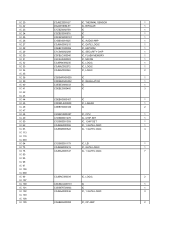
... RING INS SHEET 1 K860 DFMX1195YA SD INS SHEET 1 K861 DRHM5104ZA SCREW 3 K862 DFHG1812ZA SPACE PWB HOLD MP 1 K863 DFMX1198ZA INS SHEET, HEAT PIPE 1 K864 DFMY3151ZA MEMORY HEAT PLATE 1 K865 DFGK0133ZA SD LED SHEET 1 K866 DFHR6184ZA DC USB COVER HOOK 1 K868 DFHR7518ZA INSULATION SHEET 1 K869 DFHE0965ZA FPC CONDUCTION TAPE 1 K870 DFHE0967ZA EMP...
... RING INS SHEET 1 K860 DFMX1195YA SD INS SHEET 1 K861 DRHM5104ZA SCREW 3 K862 DFHG1812ZA SPACE PWB HOLD MP 1 K863 DFMX1198ZA INS SHEET, HEAT PIPE 1 K864 DFMY3151ZA MEMORY HEAT PLATE 1 K865 DFGK0133ZA SD LED SHEET 1 K866 DFHR6184ZA DC USB COVER HOOK 1 K868 DFHR7518ZA INSULATION SHEET 1 K869 DFHE0965ZA FPC CONDUCTION TAPE 1 K870 DFHE0967ZA EMP...
Service Manual
Page 85
... 25 C0CBCBC00181 IC 1 IC 26 C1BB00001025 IC, AUDIO AMP 1 IC 27 C0JBAS000215 IC, GATE LOGIC 1 IC 28 C3EBFC000056 IC, EEPROM 1 IC 29 C1CB00002268 IC, SECURITY CHIP 1 IC 30 C3FBLC000040 IC, FLASH MEMORY 1 IC 31 C2CBJA000003 IC, MICON 1 IC 32 C0JBAN000235 IC, LOGIC 1 IC 33 C0JBAZ002372 IC, LOGIC 1 IC 34 C0JBAZ002346 IC, LOGIC...
... 25 C0CBCBC00181 IC 1 IC 26 C1BB00001025 IC, AUDIO AMP 1 IC 27 C0JBAS000215 IC, GATE LOGIC 1 IC 28 C3EBFC000056 IC, EEPROM 1 IC 29 C1CB00002268 IC, SECURITY CHIP 1 IC 30 C3FBLC000040 IC, FLASH MEMORY 1 IC 31 C2CBJA000003 IC, MICON 1 IC 32 C0JBAN000235 IC, LOGIC 1 IC 33 C0JBAZ002372 IC, LOGIC 1 IC 34 C0JBAZ002346 IC, LOGIC...
