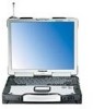
Notebook Computer
Page 10
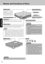
... RAM Module Slot ( "RAM Module") Speaker To adjust the volume: Fn + F5 / Fn + F6 Speaker on which it is sitting. • If floppy disks, magnetic memory cards, or other antenna or transmitter. Optional Port Replicator contains TNC connector for "Mute" under "Microphone Balance" of operation. For more information, read the manual...
... RAM Module Slot ( "RAM Module") Speaker To adjust the volume: Fn + F5 / Fn + F6 Speaker on which it is sitting. • If floppy disks, magnetic memory cards, or other antenna or transmitter. Optional Port Replicator contains TNC connector for "Mute" under "Microphone Balance" of operation. For more information, read the manual...
Notebook Computer
Page 25
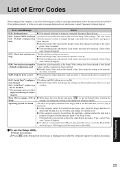
... and time correctly. Run the Setup Utility and change the settings in the memory that the disk is secured correctly. If the hard disk is no port conflicts. If a device is not shown here, contact Panasonic Technical Support. If the problem persists, or if the error code or message... has failed repeatedly, so the Setup Utility settings have been returned to run the Setup Utility 1 Restart the computer. 2 Press F2 while [Panasonic] boot screen is displayed soon after the computer begins the startup procedure. Run the Setup Utility and load the default values, then change the settings...
... and time correctly. Run the Setup Utility and change the settings in the memory that the disk is secured correctly. If the hard disk is no port conflicts. If a device is not shown here, contact Panasonic Technical Support. If the problem persists, or if the error code or message... has failed repeatedly, so the Setup Utility settings have been returned to run the Setup Utility 1 Restart the computer. 2 Press F2 while [Panasonic] boot screen is displayed soon after the computer begins the startup procedure. Run the Setup Utility and load the default values, then change the settings...
Notebook Computer
Page 40
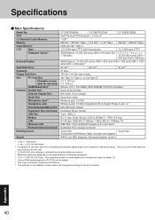
... function. *4 Maximum resolution depends on the specifications of the main memory is allotted automatically depending on the computer's operating status. CPU L2 (Second) Cache Memory Memory Video Memory LCD Type Displayed Colors*3 External Display Hard Disk Drive Keyboard Floppy ... External Keyboard/Mouse Port Expansion Bus Connector USB Port Modem LAN Wireless LAN External Antenna Connector Pointing Device Sound CF-29ETKGZKM CF-29ETPGZKM CF-29E3KGZKM Intel® Pentium® M Processor 1.3 GHz LV 1 MB*1 256 MB*1 (768 MB*1 Max.) 512 MB*1 (1 GB*1Max.) 256 MB*1 ...
... function. *4 Maximum resolution depends on the specifications of the main memory is allotted automatically depending on the computer's operating status. CPU L2 (Second) Cache Memory Memory Video Memory LCD Type Displayed Colors*3 External Display Hard Disk Drive Keyboard Floppy ... External Keyboard/Mouse Port Expansion Bus Connector USB Port Modem LAN Wireless LAN External Antenna Connector Pointing Device Sound CF-29ETKGZKM CF-29ETPGZKM CF-29E3KGZKM Intel® Pentium® M Processor 1.3 GHz LV 1 MB*1 256 MB*1 (768 MB*1 Max.) 512 MB*1 (1 GB*1Max.) 256 MB*1 ...
Notebook Computer
Page 43
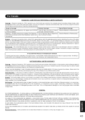
...factory installed) Batteries, CD-ROM (unless factory installed), Port Replicator, Extra Memory Modules and all other claims, whether or not of similar character. Fri. (excluding holidays) for your Panasonic Computer product. Panasonic Canada Inc. ("PCI") warrants to the terms of this software media ...OR FROM THE USE OF THE COMPUTER PRODUCT, INCLUDING, WITHOUT LIMITATION, LOSS OF DATA, BUSINESS, PROFIT OR GOODWILL. For Canada PANASONIC COMPUTER AND PERIPHERALS LIMITED WARRANTY Coverage - Please refer to replacement of the defect claimed, at the above address, within the ...
...factory installed) Batteries, CD-ROM (unless factory installed), Port Replicator, Extra Memory Modules and all other claims, whether or not of similar character. Fri. (excluding holidays) for your Panasonic Computer product. Panasonic Canada Inc. ("PCI") warrants to the terms of this software media ...OR FROM THE USE OF THE COMPUTER PRODUCT, INCLUDING, WITHOUT LIMITATION, LOSS OF DATA, BUSINESS, PROFIT OR GOODWILL. For Canada PANASONIC COMPUTER AND PERIPHERALS LIMITED WARRANTY Coverage - Please refer to replacement of the defect claimed, at the above address, within the ...

Service Manual
Page 9
... OK, etc.) Error Diagnosis by checking beep sound or error code. The condition of the main body is placed into automatic stop. Normal finish .....After memory checking, a beep sound is issued once and the set is diagnosed by Checking Beep Signal Sound The beep sound is as follows: (Length of bar...
... OK, etc.) Error Diagnosis by checking beep sound or error code. The condition of the main body is placed into automatic stop. Normal finish .....After memory checking, a beep sound is issued once and the set is diagnosed by Checking Beep Signal Sound The beep sound is as follows: (Length of bar...

Service Manual
Page 10
...Keyboard locked - Default configuration used Previous POST did not complete successfully. If the error persists, check the system battery or contact Panasonic Technical Support. 0260 System timer error The timer test failed. Default configuration used System CMOS has been corrupted or modified incorrectly, ... is booted. 0281 Memory Size found by POST differed from EISA CMOS. 3-1 This error is cleared the next time the system is dead - Run Setup. List of except the messages marked below with an asterisk (*), write down the message and contact Panasonic Technical Support. If...
...Keyboard locked - Default configuration used Previous POST did not complete successfully. If the error persists, check the system battery or contact Panasonic Technical Support. 0260 System timer error The timer test failed. Default configuration used System CMOS has been corrupted or modified incorrectly, ... is booted. 0281 Memory Size found by POST differed from EISA CMOS. 3-1 This error is cleared the next time the system is dead - Run Setup. List of except the messages marked below with an asterisk (*), write down the message and contact Panasonic Technical Support. If...

Service Manual
Page 11
...Enter Setup and see if fixed disk and drive A: are properly identified. 02D0 System cache error - BIOS attempts to extended DMA (Direct Memory Access) registers. 02F6: Software NMI Failed ServerBIOS2 test error: Cannot generate software NMI (Non-Maskable Interrupt). 02F7: Fail - Parity is a...error found in binary data. Each 1 (one) in System, Extended or Shadow memory. Invalid System Configuration Data Problem with NVRAM (CMOS) data. I/O device IRQ conflict I /O bus. Cache disabled Contact Panasonic Technical Support. 02F0: CPU ID: CPU socket number for the specified device. device ...
...Enter Setup and see if fixed disk and drive A: are properly identified. 02D0 System cache error - BIOS attempts to extended DMA (Direct Memory Access) registers. 02F6: Software NMI Failed ServerBIOS2 test error: Cannot generate software NMI (Non-Maskable Interrupt). 02F7: Fail - Parity is a...error found in binary data. Each 1 (one) in System, Extended or Shadow memory. Invalid System Configuration Data Problem with NVRAM (CMOS) data. I/O device IRQ conflict I /O bus. Cache disabled Contact Panasonic Technical Support. 02F0: CPU ID: CPU socket number for the specified device. device ...
Service Manual
Page 14
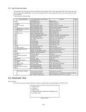
... Reg 25 VIDEO 26 (Display related) VGA ALL TEST SVGA RAM TEST 27 DISK 28 (FDD, HDD) FD WT/RD/WP TEST HDD ALL TEST 29 UNIQUE 30 (Individual functions) ECP REGISTER R/W EPP REGISTER R/W 31 EXT. Modem test 4. Quit menu screen 5-2 If you want to choose items from the menu...Test items shown on the screen 1 SPEAKER TEST 2 VESA MODE TEST 3 CPU 4 (CPU related) A20 GATE TEST CACHE ON/OFF TEST 5 NPU OPERAND TEST 6 RAM (Memory related) RAM STANDARD TEST 7 CONTROL DMA PAGE REG TEST 8 (Control ICs on FD 1. Automatic Test Test execution From the menu screen shown below . List of...
... Reg 25 VIDEO 26 (Display related) VGA ALL TEST SVGA RAM TEST 27 DISK 28 (FDD, HDD) FD WT/RD/WP TEST HDD ALL TEST 29 UNIQUE 30 (Individual functions) ECP REGISTER R/W EPP REGISTER R/W 31 EXT. Modem test 4. Quit menu screen 5-2 If you want to choose items from the menu...Test items shown on the screen 1 SPEAKER TEST 2 VESA MODE TEST 3 CPU 4 (CPU related) A20 GATE TEST CACHE ON/OFF TEST 5 NPU OPERAND TEST 6 RAM (Memory related) RAM STANDARD TEST 7 CONTROL DMA PAGE REG TEST 8 (Control ICs on FD 1. Automatic Test Test execution From the menu screen shown below . List of...
Service Manual
Page 17
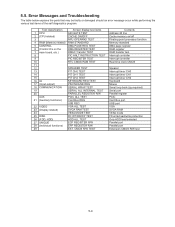
...mode FD write/read/write protection Only HDD lead selected Parallel port Parallel port Extension CMOS R/W test 5-4 CMOS R/W TEST Contents Address 20 line Cache memory on the DMA REGISTER TEST 7 main board, etc.) DMAC Transfer TEST 8 PIC HALT INSTRUCTION TEST 9 PIC REGISTER TEST 10 RTC CMOS RAM ... DISK FD WT/RD/WP TEST 26 (FDD, HDD) HDD ALL TEST 27 UNIQUE ECP REGISTER R/W 28 (Individual functions) EPP REGISTER R/W 29 EXT. Error Messages and Troubleshooting The table below explains the parts that may be faulty or damaged should an error message occur while performing the...
...mode FD write/read/write protection Only HDD lead selected Parallel port Parallel port Extension CMOS R/W test 5-4 CMOS R/W TEST Contents Address 20 line Cache memory on the DMA REGISTER TEST 7 main board, etc.) DMAC Transfer TEST 8 PIC HALT INSTRUCTION TEST 9 PIC REGISTER TEST 10 RTC CMOS RAM ... DISK FD WT/RD/WP TEST 26 (FDD, HDD) HDD ALL TEST 27 UNIQUE ECP REGISTER R/W 28 (Individual functions) EPP REGISTER R/W 29 EXT. Error Messages and Troubleshooting The table below explains the parts that may be faulty or damaged should an error message occur while performing the...

Service Manual
Page 19
.... Use new parts. 7.1.2. Use the MP Eject Lever. 7.1.3. 7 Disassembly/Reassembly Note: Power off the power. • Disconnect the AC adaptor. • Remove the optional DIMM memory card and PCMCIA card if they are connected. • Remove other devices if they are connected. Release the two Tabs, and remove the HDD U Case...
.... Use new parts. 7.1.2. Use the MP Eject Lever. 7.1.3. 7 Disassembly/Reassembly Note: Power off the power. • Disconnect the AC adaptor. • Remove the optional DIMM memory card and PCMCIA card if they are connected. • Remove other devices if they are connected. Release the two Tabs, and remove the HDD U Case...

Service Manual
Page 49
... Edge Sheet and the two MINI PCI Spacers U2. 6. Fix the SD PCB using the three Screws. MINI PCI Protector Sheet SD PCB :No3 :No2 Memory Heat Plate :No1 Note: Tighten the Screws in the numbered order (No1 to Connector (CN952) Wireless Module Heat Dissipation Rubbers Connector CN2 EXT Antenna PCB... PCB. Connect the Cable to the Connector on the EXT Antenna PCB. 5. Connect the Cable to the Connector (CN2) on the Main PCB. 8. Attach the Memory Heat Plate to the Main PCB. 2.
... Edge Sheet and the two MINI PCI Spacers U2. 6. Fix the SD PCB using the three Screws. MINI PCI Protector Sheet SD PCB :No3 :No2 Memory Heat Plate :No1 Note: Tighten the Screws in the numbered order (No1 to Connector (CN952) Wireless Module Heat Dissipation Rubbers Connector CN2 EXT Antenna PCB... PCB. Connect the Cable to the Connector on the EXT Antenna PCB. 5. Connect the Cable to the Connector (CN2) on the Main PCB. 8. Attach the Memory Heat Plate to the Main PCB. 2.

Service Manual
Page 50
... Spacer to the LAN Heat Plate. Attach the Radiation Rubber, Coil Cooling Sheet and the LCD Lamp Sheet to the LAN Heat Plate. 8. n Attaching the Memory Heat Plate Memory Heat Plate IC 0~1mm 0~1mm 7.2.14. Fix the three Speaker Angles to the Speaker using the three Adhesive Tapes. 6.
... Spacer to the LAN Heat Plate. Attach the Radiation Rubber, Coil Cooling Sheet and the LCD Lamp Sheet to the LAN Heat Plate. 8. n Attaching the Memory Heat Plate Memory Heat Plate IC 0~1mm 0~1mm 7.2.14. Fix the three Speaker Angles to the Speaker using the three Adhesive Tapes. 6.

Service Manual
Page 70
... RING INS SHEET 1 K860 DFMX1195YA SD INS SHEET 1 K861 DRHM5104ZA SCREW 3 K862 DFHG1812ZA SPACE PWB HOLD MP 1 K863 DFMX1198ZA INS SHEET, HEAT PIPE 1 K864 DFMY3151ZA MEMORY HEAT PLATE 1 K865 DFGK0133ZA SD LED SHEET 1 K866 DFHR6184ZA DC USB COVER HOOK 1 K868 DFHR7518ZA INSULATION SHEET 1 K869 DFHE0965ZA FPC CONDUCTION TAPE 1 K870 DFHE0967ZA EMP...
... RING INS SHEET 1 K860 DFMX1195YA SD INS SHEET 1 K861 DRHM5104ZA SCREW 3 K862 DFHG1812ZA SPACE PWB HOLD MP 1 K863 DFMX1198ZA INS SHEET, HEAT PIPE 1 K864 DFMY3151ZA MEMORY HEAT PLATE 1 K865 DFGK0133ZA SD LED SHEET 1 K866 DFHR6184ZA DC USB COVER HOOK 1 K868 DFHR7518ZA INSULATION SHEET 1 K869 DFHE0965ZA FPC CONDUCTION TAPE 1 K870 DFHE0967ZA EMP...
Service Manual
Page 85
... 25 C0CBCBC00181 IC 1 IC 26 C1BB00001025 IC, AUDIO AMP 1 IC 27 C0JBAS000215 IC, GATE LOGIC 1 IC 28 C3EBFC000056 IC, EEPROM 1 IC 29 C1CB00002268 IC, SECURITY CHIP 1 IC 30 C3FBLC000040 IC, FLASH MEMORY 1 IC 31 C2CBJA000003 IC, MICON 1 IC 32 C0JBAN000235 IC, LOGIC 1 IC 33 C0JBAZ002372 IC, LOGIC 1 IC 34 C0JBAZ002346 IC, LOGIC...
... 25 C0CBCBC00181 IC 1 IC 26 C1BB00001025 IC, AUDIO AMP 1 IC 27 C0JBAS000215 IC, GATE LOGIC 1 IC 28 C3EBFC000056 IC, EEPROM 1 IC 29 C1CB00002268 IC, SECURITY CHIP 1 IC 30 C3FBLC000040 IC, FLASH MEMORY 1 IC 31 C2CBJA000003 IC, MICON 1 IC 32 C0JBAN000235 IC, LOGIC 1 IC 33 C0JBAZ002372 IC, LOGIC 1 IC 34 C0JBAZ002346 IC, LOGIC...
