User Guide
Page 2
... Award® is a registered trademark of AMD Corporation. Alternatively, please try the following help resources for FAQ, technical guide, BIOS updates, driver updates, and other countries. Revision History Revision V1.0 Revision History First release for PCB 1.X Date March 2007 Technical Support If a problem ...Technologies Ltd. Netware® is a registered trademark of M ICRO-STAR INTERNATIONAL. Copyright Notice The material in this document, but no solution can be obtained from the user's manual, please contact your system and no guarantee is given as to make changes...
... Award® is a registered trademark of AMD Corporation. Alternatively, please try the following help resources for FAQ, technical guide, BIOS updates, driver updates, and other countries. Revision History Revision V1.0 Revision History First release for PCB 1.X Date March 2007 Technical Support If a problem ...Technologies Ltd. Netware® is a registered trademark of M ICRO-STAR INTERNATIONAL. Copyright Notice The material in this document, but no solution can be obtained from the user's manual, please contact your system and no guarantee is given as to make changes...
User Guide
Page 8
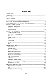
... 1-2 Mainboard Layout 1-4 Packing Checklist 1-5 Chapter 2 Hardware Setup 2-1 Quick Components Guide 2-2 CPU (Central Processing Unit 2-3 Memory ...2-7 Power Supply ...2-9 Back Panel ...2-10 Connectors ...2-12 Jumper ...2-19 Slots ...2-20 Chapter 3 BIOS Setup 3-1 Entering Setup ...3-2 The Main Menu ...3-4 Standard CMOS Features 3-6 Advanced BIOS Features 3-8 Integrated Peripherals 3-11 Power Management Setup 3-13 PNP/PCI Configurations 3-16 H/W Monitor ...3-18 Frequency/Voltage Control 3-19 Load Fail-Safe/ Optimized Defaults 3-23 BIOS Setting Password 3-24 Appendix A Dual Core...
... 1-2 Mainboard Layout 1-4 Packing Checklist 1-5 Chapter 2 Hardware Setup 2-1 Quick Components Guide 2-2 CPU (Central Processing Unit 2-3 Memory ...2-7 Power Supply ...2-9 Back Panel ...2-10 Connectors ...2-12 Jumper ...2-19 Slots ...2-20 Chapter 3 BIOS Setup 3-1 Entering Setup ...3-2 The Main Menu ...3-4 Standard CMOS Features 3-6 Advanced BIOS Features 3-8 Integrated Peripherals 3-11 Power Management Setup 3-13 PNP/PCI Configurations 3-16 H/W Monitor ...3-18 Frequency/Voltage Control 3-19 Load Fail-Safe/ Optimized Defaults 3-23 BIOS Setting Password 3-24 Appendix A Dual Core...

User Guide
Page 9
Clock ...A-6 Voltage ...A-7 FAN Speed ...A-8 Temperature ...A-9 User Profile ...A-10 Appendix B Realtek ALC888 Audio B-1 Installing the Realtek Audio Driver B-2 Software Configuration B-4 Hardware Setup B-19 ix
Clock ...A-6 Voltage ...A-7 FAN Speed ...A-8 Temperature ...A-9 User Profile ...A-10 Appendix B Realtek ALC888 Audio B-1 Installing the Realtek Audio Driver B-2 Software Configuration B-4 Hardware Setup B-19 ix
User Guide
Page 11
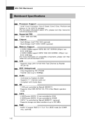
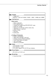
... 400Mbps Audio - MS-7365 Mainboard Mainboard Specifications Processor Support - Supports 7.1 channels audio out - Intel® Core 2 Extreme, Core 2 Quad, Core 2 Duo, Pentium and Celeron in the LGA775 package (For the latest information about CPU, please visit http://www.msi. Chip integrated by Marvell 88SE6111 (optional) - Com pliant with Azalia Spec IDE - 1 IDE port controlled by ICH9R - ECC/ 4GB Max) (For more information on compatible components, please visit http:/ /www.msi.com.tw/testreport.htm) LAN - Supports...
... 400Mbps Audio - MS-7365 Mainboard Mainboard Specifications Processor Support - Supports 7.1 channels audio out - Intel® Core 2 Extreme, Core 2 Quad, Core 2 Duo, Pentium and Celeron in the LGA775 package (For the latest information about CPU, please visit http://www.msi. Chip integrated by Marvell 88SE6111 (optional) - Com pliant with Azalia Spec IDE - 1 IDE port controlled by ICH9R - ECC/ 4GB Max) (For more information on compatible components, please visit http:/ /www.msi.com.tw/testreport.htm) LAN - Supports...
User Guide
Page 12
..., 1.2MB, 1.44MB and 2.88MB Connectors Back panel - 1 PS/2 mouse port - 1 PS/2 keyboard port - 1 Parallel port supporting SPP/EPP/ECP mode - 1 serial port (COM1) - 1 VGA port (for G33 Neo Combo series only) - 1 IEEE1394 port (optional) - 4 USB 2.0 Ports - 1 LAN jack - 6 audio jacks On-Board Pinheaders - 4 USB 2.0 pinheaders - 1 IEEE1394 pinheader (optional) - 1 Chassis Intrusion Switch pinheader - 1 Front Panel Audio pinheader - 1 CD-In pinheader - 1 SPDIF-out pinheader Slots - 1 PCI Express x 16 slot - 3 PCI Express x 1 slots - 2 PCI slots, support 3.3V/ 5V PCI bus Interface Form Factor -
..., 1.2MB, 1.44MB and 2.88MB Connectors Back panel - 1 PS/2 mouse port - 1 PS/2 keyboard port - 1 Parallel port supporting SPP/EPP/ECP mode - 1 serial port (COM1) - 1 VGA port (for G33 Neo Combo series only) - 1 IEEE1394 port (optional) - 4 USB 2.0 Ports - 1 LAN jack - 6 audio jacks On-Board Pinheaders - 4 USB 2.0 pinheaders - 1 IEEE1394 pinheader (optional) - 1 Chassis Intrusion Switch pinheader - 1 Front Panel Audio pinheader - 1 CD-In pinheader - 1 SPDIF-out pinheader Slots - 1 PCI Express x 16 slot - 3 PCI Express x 1 slots - 2 PCI slots, support 3.3V/ 5V PCI bus Interface Form Factor -

User Guide
Page 23
Hardware Setup Power Supply ATX 24-Pin Power Connector: JPWR3 This connector allows you to avoid wrong installation. 12 24 JPWR3 1 13 Pin Definition PIN SIGNAL PIN SIGNAL ...connectors are connected to proper ATX power supplies to the image at the right hand). If you like. To connect the ATX 24-pin power supply, make sure the plug of the mainboard. 2. Then push down the power supply firmly into the connector. Power supply of 350 watts (and above) is used to provide power to use the 20-pin ATX power supply as you 'd like to the CPU. 3 4 1 2 JPW1 Pin Definition PIN...
Hardware Setup Power Supply ATX 24-Pin Power Connector: JPWR3 This connector allows you to avoid wrong installation. 12 24 JPWR3 1 13 Pin Definition PIN SIGNAL PIN SIGNAL ...connectors are connected to proper ATX power supplies to the image at the right hand). If you like. To connect the ATX 24-pin power supply, make sure the plug of the mainboard. 2. Then push down the power supply firmly into the connector. Power supply of 350 watts (and above) is used to provide power to use the 20-pin ATX power supply as you 'd like to the CPU. 3 4 1 2 JPW1 Pin Definition PIN...
User Guide
Page 26
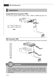
IDE1 Important If you install two IDE devices on the same cable, you must configure the drives separately to IDE device's documentation supplied by setting jumpers. MS-7365 Mainboard Connectors Floppy Disk Drive Connector: FDD1 This connector supports 360KB, 720KB, 1.2MB, 1.44MB or 2.88MB floppy disk drive. Refer to master / slave mode by the vendors for jumper setting instructions. 2-12 FDD1 IDE Connector: IDE1 This connector supports IDE hard disk drives, optical disk drives and other IDE devices.
IDE1 Important If you install two IDE devices on the same cable, you must configure the drives separately to IDE device's documentation supplied by setting jumpers. MS-7365 Mainboard Connectors Floppy Disk Drive Connector: FDD1 This connector supports 360KB, 720KB, 1.2MB, 1.44MB or 2.88MB floppy disk drive. Refer to master / slave mode by the vendors for jumper setting instructions. 2-12 FDD1 IDE Connector: IDE1 This connector supports IDE hard disk drives, optical disk drives and other IDE devices.
User Guide
Page 28
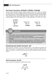
... supports fan control. To clear the warning, you must enter the BIOS utility and clear the record. If the chassis is Ground and should be connected to a 2-pin chassis switch. Fan cooler set with speed sensor to GND. Please refer to the actual CPU temperature. Control SENSOR +12V GND CPUFAN1 SE NS OR +1 2V GND SYSFAN1 SE NS OR +1 2V GND SYSFAN2 Important 1. You can install Dual Core Center utility that the red wire...
... supports fan control. To clear the warning, you must enter the BIOS utility and clear the record. If the chassis is Ground and should be connected to a 2-pin chassis switch. Fan cooler set with speed sensor to GND. Please refer to the actual CPU temperature. Control SENSOR +12V GND CPUFAN1 SE NS OR +1 2V GND SYSFAN1 SE NS OR +1 2V GND SYSFAN2 Important 1. You can install Dual Core Center utility that the red wire...
User Guide
Page 33
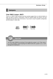
Hardware Setup Jumpers Clear CMOS Jumper: JBAT1 There is on . JBAT1 1 1 3 Keep Data 1 3 Clear Data Important You can automatically boot OS every time it will damage the mainboard. 2-19 W ith the CMOS RAM, the system can clear CMOS by shorting 2-3 pin while the system is turned on ; it is off. Then return to clear data. Avoid clearing the CMOS while the system is a CMOS RAM onboard that has a power supply from an external battery to keep the data of system configuration. If you want to clear the system configuration, set the jumper to 1-2 pin position.
Hardware Setup Jumpers Clear CMOS Jumper: JBAT1 There is on . JBAT1 1 1 3 Keep Data 1 3 Clear Data Important You can automatically boot OS every time it will damage the mainboard. 2-19 W ith the CMOS RAM, the system can clear CMOS by shorting 2-3 pin while the system is turned on ; it is off. Then return to clear data. Avoid clearing the CMOS while the system is a CMOS RAM onboard that has a power supply from an external battery to keep the data of system configuration. If you want to clear the system configuration, set the jumper to 1-2 pin position.
User Guide
Page 34
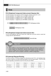
... with PCI specifications. 32-bit PCI Slot Important 1. The PCI Express x 16 supports up to configure any necessary hardware or software settings for the expansion card to 2.0 GB/s transfer rate. The PCI IRQ pins are hardware lines over which devices can send interrupt signals to the PCI bus pins as jumpers, switches or BIOS configuration. PCI Express x16 Slot PCI Express x1 Slot PCI (Peripheral Component Interconnect) Slot The PCI slot supports LAN card, SCSI card, USB card, and other add-on cards that you unplug the power supply first. PCI Interrupt...
... with PCI specifications. 32-bit PCI Slot Important 1. The PCI Express x 16 supports up to configure any necessary hardware or software settings for the expansion card to 2.0 GB/s transfer rate. The PCI IRQ pins are hardware lines over which devices can send interrupt signals to the PCI bus pins as jumpers, switches or BIOS configuration. PCI Express x16 Slot PCI Express x1 Slot PCI (Peripheral Component Interconnect) Slot The PCI slot supports LAN card, SCSI card, USB card, and other add-on cards that you unplug the power supply first. PCI Interrupt...
User Guide
Page 41
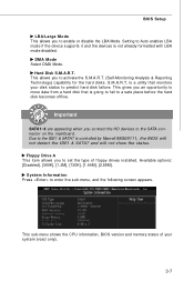
... you to set the type of your disk status to predict hard disk failure. is a utility that is going to fail to a safe place before the hard disk becomes offline. Due to the IDE1 & SATA7 is not already formatted with LBA mode disabled. This sub-menu shows the CPU information, BIOS version and memory status of floppy drives installed. This gives you an opportunity to move data from a hard disk that monitors your...
... you to set the type of your disk status to predict hard disk failure. is a utility that is going to fail to a safe place before the hard disk becomes offline. Due to the IDE1 & SATA7 is not already formatted with LBA mode disabled. This sub-menu shows the CPU information, BIOS version and memory status of floppy drives installed. This gives you an opportunity to move data from a hard disk that monitors your...
User Guide
Page 42
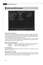
... disable it will skip some check items. Boot Up Num-Lock LED This setting is powered on the bootup screen. To successfully update the BIOS, you want to [On] will allow users to update the BIOS with a Flash utility. MS-7365 Mainboard Advanced BIOS Features Boot Sector Protection This function protects the BIOS from accidental corruption by unauthorized users or computer viruses. Full Screen LOGO Display This item enables you should enable...
... disable it will skip some check items. Boot Up Num-Lock LED This setting is powered on the bootup screen. To successfully update the BIOS, you want to [On] will allow users to update the BIOS with a Flash utility. MS-7365 Mainboard Advanced BIOS Features Boot Sector Protection This function protects the BIOS from accidental corruption by unauthorized users or computer viruses. Full Screen LOGO Display This item enables you should enable...
User Guide
Page 43
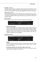
... select the MPS version supported by where application code can execute and where it cannot. This setting controls the exact memory size shared to the onboard VGA card. BIOS Setup IOAPIC Function This field is able to enable or disable the APIC (Advanced Programmable Interrupt Controller). Enabling APIC mode will provide you to select which version to insert code in APIC mode. W hen a malicious worm attempts to use, consult the vendor...
... select the MPS version supported by where application code can execute and where it cannot. This setting controls the exact memory size shared to the onboard VGA card. BIOS Setup IOAPIC Function This field is able to enable or disable the APIC (Advanced Programmable Interrupt Controller). Enabling APIC mode will provide you to select which version to insert code in APIC mode. W hen a malicious worm attempts to use, consult the vendor...
User Guide
Page 45
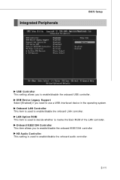
... Support Select [Enabled] if you to use a USB-interfaced device in the operating system. Onboard IEEE1394 Controller This item allows you need to enable/disable the onboard IEEE1394 controller. HD Audio Controller This setting is used to invoke the Boot ROM of the LAN controller. Integrated Peripherals BIOS Setup USB Controller This setting allows you to enable/disable the onboard audio controller. 3-11 Onboard LAN Controller This item is used to decide whether to enable/disable the onboard LAN controller. LAN Option ROM This item is used to enable/disable the onboard USB...
... Support Select [Enabled] if you to use a USB-interfaced device in the operating system. Onboard IEEE1394 Controller This item allows you need to enable/disable the onboard IEEE1394 controller. HD Audio Controller This setting is used to invoke the Boot ROM of the LAN controller. Integrated Peripherals BIOS Setup USB Controller This setting allows you to enable/disable the onboard audio controller. 3-11 Onboard LAN Controller This item is used to decide whether to enable/disable the onboard LAN controller. LAN Option ROM This item is used to enable/disable the onboard USB...
User Guide
Page 48
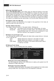
... VGA BIOS From S3 W hen ACPI Standby State is set to [S3], users can select the options in this field, all devices except CPU will be awakened from what power saving modes when input signal of the PS/2 keyboard is detected. 3-14 Power Button Function This feature sets the function of the card does not support the initialization feature, the display may work abnormally or not function after a power failure...
... VGA BIOS From S3 W hen ACPI Standby State is set to [S3], users can select the options in this field, all devices except CPU will be awakened from what power saving modes when input signal of the PS/2 keyboard is detected. 3-14 Power Button Function This feature sets the function of the card does not support the initialization feature, the display may work abnormally or not function after a power failure...
User Guide
Page 50
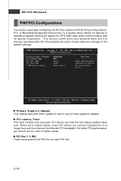
... This item controls how long each PCI slot. 3-16 For better PCI performance, you should make any changes to operate at speeds nearing the speed the CPU itself uses when communicating with its special components. MS-7365 Mainboard PNP/PCI Configurations This section describes configuring the PCI bus system and PnP (Plug & Play) feature. Primary Graphic's Adapter This setting specifies which allows I/O devices to the default settings. This section covers some very...
... This item controls how long each PCI slot. 3-16 For better PCI performance, you should make any changes to operate at speeds nearing the speed the CPU itself uses when communicating with its special components. MS-7365 Mainboard PNP/PCI Configurations This section describes configuring the PCI bus system and PnP (Plug & Play) feature. Primary Graphic's Adapter This setting specifies which allows I/O devices to the default settings. This section covers some very...
User Guide
Page 52
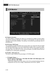
.... CPU Min. MS-7365 Mainboard H/W Monitor Chassis Intrusion The field enables or disables the feature of recording the chassis intrusion status and issuing a warning message if the chassis is used to specify the percentage of CPUFAN spped. ---- FAN speed (%) This item is once opened. It provides several sections to keep it with in a specific range. The setting of the monitored hardware devices/ components such as CPU voltage, temperatures...
.... CPU Min. MS-7365 Mainboard H/W Monitor Chassis Intrusion The field enables or disables the feature of recording the chassis intrusion status and issuing a warning message if the chassis is used to specify the percentage of CPUFAN spped. ---- FAN speed (%) This item is once opened. It provides several sections to keep it with in a specific range. The setting of the monitored hardware devices/ components such as CPU voltage, temperatures...
User Guide
Page 54
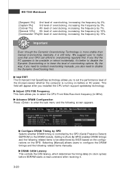
... than manual overclocking, basically, it . 3-20 Advance DRAM Configuration Press to configure the DRAM timings and the following screen appears. DRAM CAS# Latency This controls the CAS latency, which support speedstep technology. Selecting [Manual] allows users to enter the sub-menu and the following related items manually. We suggest user to make sure that your CPU can afford to select the CPU Front Side Bus clock frequency (in clock cycles) before SDRAM starts a read...
... than manual overclocking, basically, it . 3-20 Advance DRAM Configuration Press to configure the DRAM timings and the following screen appears. DRAM CAS# Latency This controls the CAS latency, which support speedstep technology. Selecting [Manual] allows users to enter the sub-menu and the following related items manually. We suggest user to make sure that your CPU can afford to select the CPU Front Side Bus clock frequency (in clock cycles) before SDRAM starts a read...

User Guide
Page 55
...). SB Core Power Adjust the South Bridge core voltage. 3-21 If insufficient time is installed in the system. M emory Voltage (V) Adjusting the memory voltage can increase the DDR speed. NB Voltage Adjust the North Bridge chipset voltage. Auto Disable DIMM/PCI Freque This item is used when DRAM is installed in the system. BIOS Setup DRAM RAS# to CAS# Delay This field allows you to set to [Enabled], the system will remove (turn off) clocks from...
...). SB Core Power Adjust the South Bridge core voltage. 3-21 If insufficient time is installed in the system. M emory Voltage (V) Adjusting the memory voltage can increase the DDR speed. NB Voltage Adjust the North Bridge chipset voltage. Auto Disable DIMM/PCI Freque This item is used when DRAM is installed in the system. BIOS Setup DRAM RAS# to CAS# Delay This field allows you to set to [Enabled], the system will remove (turn off) clocks from...

User Guide
Page 61
... function of this utility, we have to remind you install a graphics card of other brand, only hardware status of the MSI mainboard would be available. A-3 Dual Core Center Main Before using this utility. Introduction: Click each button appearing above to enter sub-menu to make further configuration or to enable or disable the Dynamic Overclocking Technology. MB Click MB button to read current GPU temperature, GPU clock and memory clock of graphics card will show below...
... function of this utility, we have to remind you install a graphics card of other brand, only hardware status of the MSI mainboard would be available. A-3 Dual Core Center Main Before using this utility. Introduction: Click each button appearing above to enter sub-menu to make further configuration or to enable or disable the Dynamic Overclocking Technology. MB Click MB button to read current GPU temperature, GPU clock and memory clock of graphics card will show below...


