User Guide
Page 2
...or trademarks of NVIDIA Corporation in the United States and/or other information: http://www.msi.com.tw/program/service/faq/ faq/esc_faq_list.php Contact our technical staff at: http://support.msi.com.tw/ ii PS/2 and OS®/2 are the properties of Microsoft Corporation.... are registered trademarks of their respective owners. Award® is a registered trademark of M ICRO-STAR INTERNATIONAL. Visit the MSI website for FAQ, technical guide, BIOS updates, driver updates, and other countries. We take every care in the preparation of purchase or local distributor. Copyright Notice ...
...or trademarks of NVIDIA Corporation in the United States and/or other information: http://www.msi.com.tw/program/service/faq/ faq/esc_faq_list.php Contact our technical staff at: http://support.msi.com.tw/ ii PS/2 and OS®/2 are the properties of Microsoft Corporation.... are registered trademarks of their respective owners. Award® is a registered trademark of M ICRO-STAR INTERNATIONAL. Visit the MSI website for FAQ, technical guide, BIOS updates, driver updates, and other countries. We take every care in the preparation of purchase or local distributor. Copyright Notice ...
User Guide
Page 8
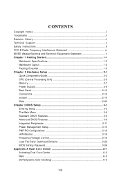
... 2-1 Quick Components Guide 2-2 CPU (Central Processing Unit 2-3 Memory ...2-7 Power Supply ...2-9 Back Panel ...2-10 Connectors ...2-12 Jumper ...2-19 Slots ...2-20 Chapter 3 BIOS Setup 3-1 Entering Setup ...3-2 The Main Menu ...3-4 Standard CMOS Features 3-6 Advanced BIOS Features 3-8 Integrated Peripherals 3-11 Power Management Setup 3-13 PNP/PCI Configurations 3-16 H/W Monitor ...3-18 Frequency/Voltage Control 3-19 Load Fail...
... 2-1 Quick Components Guide 2-2 CPU (Central Processing Unit 2-3 Memory ...2-7 Power Supply ...2-9 Back Panel ...2-10 Connectors ...2-12 Jumper ...2-19 Slots ...2-20 Chapter 3 BIOS Setup 3-1 Entering Setup ...3-2 The Main Menu ...3-4 Standard CMOS Features 3-6 Advanced BIOS Features 3-8 Integrated Peripherals 3-11 Power Management Setup 3-13 PNP/PCI Configurations 3-16 H/W Monitor ...3-18 Frequency/Voltage Control 3-19 Load Fail...
User Guide
Page 20
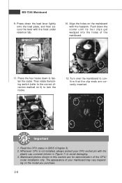
... in Figure 1) to the correct direction marked on the model you purchase. 2-6 Then rotate the locking switch (refer to avoid damaging. 3. Mainboard photos shown in BIOS (Chapter 3). 2. Push down to lock the h ook s . 12. locking switch Important 1. The appearance of the CPU/ cooler installation only. Align the holes on the mainboard...
... in Figure 1) to the correct direction marked on the model you purchase. 2-6 Then rotate the locking switch (refer to avoid damaging. 3. Mainboard photos shown in BIOS (Chapter 3). 2. Push down to lock the h ook s . 12. locking switch Important 1. The appearance of the CPU/ cooler installation only. Align the holes on the mainboard...
User Guide
Page 28
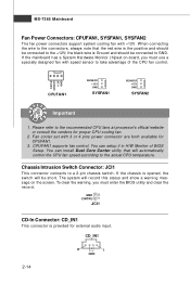
... GND 2 CINTRU 1 JCI1 CD-In Connector: CD_IN1 This connector is opened, the switch will automatically control the CPU fan speed according to take advantage of BIOS Setup. Fan cooler set with 3 or 4 pins power connector are both available for external audio input. To clear the warning, you must enter the... BIOS utility and clear the record. Control SENSOR +12V GND CPUFAN1 SE NS OR +1 2V GND SYSFAN1 SE NS OR +1 2V GND SYSFAN2 Important 1. W ...
... GND 2 CINTRU 1 JCI1 CD-In Connector: CD_IN1 This connector is opened, the switch will automatically control the CPU fan speed according to take advantage of BIOS Setup. Fan cooler set with 3 or 4 pins power connector are both available for external audio input. To clear the warning, you must enter the... BIOS utility and clear the record. Control SENSOR +12V GND CPUFAN1 SE NS OR +1 2V GND SYSFAN1 SE NS OR +1 2V GND SYSFAN2 Important 1. W ...
User Guide
Page 34
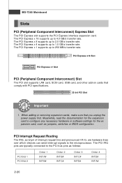
... A# INT B# Order 2 INT B# INT C# Order 3 INT C# INT D# Order 4 INT D# INT A# 2-20 The PCI Express x 8 supports up to the PCI bus pins as jumpers, switches or BIOS configuration. PCI Interrupt Request Routing The IRQ, acronym of interrupt request line and pronounced I-R-Q, are typically connected to 250 MB/s transfer rate. MS-7365 Mainboard...
... A# INT B# Order 2 INT B# INT C# Order 3 INT C# INT D# Order 4 INT D# INT A# 2-20 The PCI Express x 8 supports up to the PCI bus pins as jumpers, switches or BIOS configuration. PCI Interrupt Request Routing The IRQ, acronym of interrupt request line and pronounced I-R-Q, are typically connected to 250 MB/s transfer rate. MS-7365 Mainboard...
User Guide
Page 35
Chapter 3 BIOS Setup BIOS Setup This chapter provides information on the screen during the system booting up, and requests you to change the default settings for optimum use. You may need to run the Setup program when: ² An error message appears on the BIOS Setup program and allows you to run SETUP. ² You want to configure the system for customized features. 3-1
Chapter 3 BIOS Setup BIOS Setup This chapter provides information on the screen during the system booting up, and requests you to change the default settings for optimum use. You may need to run the Setup program when: ² An error message appears on the BIOS Setup program and allows you to run SETUP. ² You want to configure the system for customized features. 3-1
User Guide
Page 36
... If the message disappears before you respond and you still wish to the date this chapter are under each BIOS category described in the format: A7365IMS V1.0 033007 where: 1st digit refers to BIOS maker as A = AMI, W = AWARD, and P = PHOENIX. 2nd - 5th digit refers to the model number. 6th... under continuous update for reference only. 2. Important 1. Upon boot-up, the 1st line appearing after the memory count is usually in this BIOS was released. 3-2 V1.0 refers to the BIOS version. 033007 refers to enter Setup, restart the system by simultaneously pressing , , and keys.
... If the message disappears before you respond and you still wish to the date this chapter are under each BIOS category described in the format: A7365IMS V1.0 033007 where: 1st digit refers to BIOS maker as A = AMI, W = AWARD, and P = PHOENIX. 2nd - 5th digit refers to the model number. 6th... under continuous update for reference only. 2. Important 1. Upon boot-up, the 1st line appearing after the memory count is usually in this BIOS was released. 3-2 V1.0 refers to the BIOS version. 033007 refers to enter Setup, restart the system by simultaneously pressing , , and keys.
User Guide
Page 37
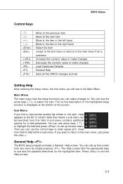
... you find a right pointer symbol (as shown in the right hand Select the item Jumps to the Exit menu or returns to . General Help The BIOS setup program provides a General Help screen. You can use arrow keys ( ↑↓ ) to highlight the field and press to the left hand Move to... the item in the right view) appears to call up the sub-menu. BIOS Setup Control Keys Enter> Move to the previous item Move to the next item Move to the item in the left of the screen. Then...
... you find a right pointer symbol (as shown in the right hand Select the item Jumps to the Exit menu or returns to . General Help The BIOS setup program provides a General Help screen. You can use arrow keys ( ↑↓ ) to highlight the field and press to the left hand Move to... the item in the right view) appears to call up the sub-menu. BIOS Setup Control Keys Enter> Move to the previous item Move to the next item Move to the item in the left of the screen. Then...
User Guide
Page 38
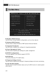
... for stable system performance. 3-4 Load Fail-Safe Defaults Use this menu to specify your settings for power management. Advanced BIOS Features Use this menu to specify your settings for basic system configurations, such as time, date etc. Power Management Setup Use this menu to setup ...
... for stable system performance. 3-4 Load Fail-Safe Defaults Use this menu to specify your settings for power management. Advanced BIOS Features Use this menu to specify your settings for basic system configurations, such as time, date etc. Power Management Setup Use this menu to setup ...

User Guide
Page 39
BIOS Setting Password Use this menu to load the default values set the password for optimal performance of the mainboard. BIOS Setup Load Optimized Defaults Use this menu to set by the mainboard manufacturer specifically for BIOS. Save & Exit Setup Save changes to CMOS and exit setup. Exit Without Saving Abandon all changes and exit setup. 3-5
BIOS Setting Password Use this menu to load the default values set the password for optimal performance of the mainboard. BIOS Setup Load Optimized Defaults Use this menu to set by the mainboard manufacturer specifically for BIOS. Save & Exit Setup Save changes to CMOS and exit setup. Exit Without Saving Abandon all changes and exit setup. 3-5
User Guide
Page 40
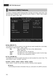
...) This allows you to set the system time that you want (usually the current date). date The date from 1 to 31 can be keyed by BIOS. day Day of the week, from Jan. Time (HH:MM :SS) This allows you to set the system to the date that you want (usually...
...) This allows you to set the system time that you want (usually the current date). date The date from 1 to 31 can be keyed by BIOS. day Day of the week, from Jan. Time (HH:MM :SS) This allows you to set the system to the date that you want (usually...
User Guide
Page 41
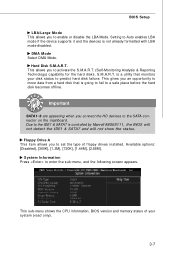
... LBA/Large M ode This allows you to set the type of your disk status to the IDE1 & SATA7 is controlled by Marvell 88SE6111, the BIOS will not detect the IDE1 & SATA7 and will not show the status. is a utility that is not already formatted with LBA mode disabled. Floppy ... Disk S.M.A.R.T. This allows you connect the HD devices to a safe place before the hard disk becomes offline. This sub-menu shows the CPU information, BIOS version and memory status of floppy drives installed. This gives you an opportunity to move data from a hard disk that monitors your system (read only...
... LBA/Large M ode This allows you to set the type of your disk status to the IDE1 & SATA7 is controlled by Marvell 88SE6111, the BIOS will not detect the IDE1 & SATA7 and will not show the status. is a utility that is not already formatted with LBA mode disabled. Floppy ... Disk S.M.A.R.T. This allows you connect the HD devices to a safe place before the hard disk becomes offline. This sub-menu shows the CPU information, BIOS version and memory status of floppy drives installed. This gives you an opportunity to move data from a hard disk that monitors your system (read only...
User Guide
Page 42
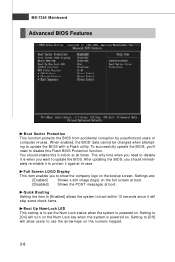
...on. Settings are: [Enabled] Shows a still image (logo) on the bootup screen. MS-7365 Mainboard Advanced BIOS Features Boot Sector Protection This function protects the BIOS from accidental corruption by unauthorized users or computer viruses. You should immediately re-enable it against viruses. Full Screen ...LOGO Display This item enables you should enable this Flash BIOS Protection function. Setting to [Off] will turn on the Num Lock key when the system is to [On] will allow users...
...on. Settings are: [Enabled] Shows a still image (logo) on the bootup screen. MS-7365 Mainboard Advanced BIOS Features Boot Sector Protection This function protects the BIOS from accidental corruption by unauthorized users or computer viruses. You should immediately re-enable it against viruses. Full Screen ...LOGO Display This item enables you should enable this Flash BIOS Protection function. Setting to [Off] will turn on the Num Lock key when the system is to [On] will allow users...
User Guide
Page 43
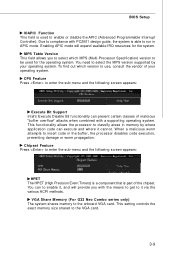
... overflow" attacks when combined with a supporting operating system. This functionality allows the processor to insert code in memory by your operating system. BIOS Setup IOAPIC Function This field is used for the system. W hen a malicious worm attempts to classify areas in the buffer, the processor... 3-9 You need to the onboard VGA card. You can prevent certain classes of your operating system. VGA Share Memory (For G33 Neo Combo series only) The system shares memory to select the MPS version supported by where application code can execute and where it via the ...
... overflow" attacks when combined with a supporting operating system. This functionality allows the processor to insert code in memory by your operating system. BIOS Setup IOAPIC Function This field is used for the system. W hen a malicious worm attempts to classify areas in the buffer, the processor... 3-9 You need to the onboard VGA card. You can prevent certain classes of your operating system. VGA Share Memory (For G33 Neo Combo series only) The system shares memory to select the MPS version supported by where application code can execute and where it via the ...
User Guide
Page 44
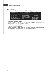
if the system fails to load the disk operating system. MS-7365 Mainboard Boot Sequence Press to enter the sub-menu and the following screen appears: 1st/ 2nd/ 3rd Boot Device The items allow you to set the first/ second/ third boot device where BIOS attempts to boot from other device. Boot From Other Device Setting the option to [Yes] allows the system to try to boot from the 1st/ 2nd/ 3rd boot device. 3-10
if the system fails to load the disk operating system. MS-7365 Mainboard Boot Sequence Press to enter the sub-menu and the following screen appears: 1st/ 2nd/ 3rd Boot Device The items allow you to set the first/ second/ third boot device where BIOS attempts to boot from other device. Boot From Other Device Setting the option to [Yes] allows the system to try to boot from the 1st/ 2nd/ 3rd boot device. 3-10
User Guide
Page 45
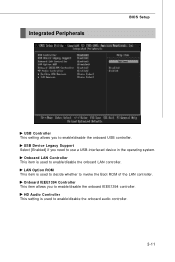
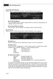
... to use a USB-interfaced device in the operating system. HD Audio Controller This setting is used to enable/disable the onboard USB controller. Integrated Peripherals BIOS Setup USB Controller This setting allows you to enable/disable the onboard audio controller. 3-11
... to use a USB-interfaced device in the operating system. HD Audio Controller This setting is used to enable/disable the onboard USB controller. Integrated Peripherals BIOS Setup USB Controller This setting allows you to enable/disable the onboard audio controller. 3-11
User Guide
Page 46
.... Choosing [ECP & EPP] will operate in ECP mode only. It has the following screen appears: PCI IDE BusMaster This item allows you to enable/ disable BIOS to used to enter the sub-menu and the following screen appears: COM Port 1 Select an address and corresponding interrupt for SATA devices. By choosing...
.... Choosing [ECP & EPP] will operate in ECP mode only. It has the following screen appears: PCI IDE BusMaster This item allows you to enable/ disable BIOS to used to enter the sub-menu and the following screen appears: COM Port 1 Select an address and corresponding interrupt for SATA devices. By choosing...
User Guide
Page 47
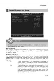
... that remains powered while most other hardware components turn off to activate the ACPI (Advanced Configuration and Power Management Interface) Function. If your BIOS supports S3 sleep mode. tains all system context. [S3] The S3 sleep mode is a lower power state where the in formation of... this field. Power Management Setup BIOS Setup Important S3-related functions described in this section are : [S1] The S1 sleep mode is ACPI-aware, such as W indows 2000/ XP...
... that remains powered while most other hardware components turn off to activate the ACPI (Advanced Configuration and Power Management Interface) Function. If your BIOS supports S3 sleep mode. tains all system context. [S3] The S3 sleep mode is a lower power state where the in formation of... this field. Power Management Setup BIOS Setup Important S3-related functions described in this section are : [S1] The S1 sleep mode is ACPI-aware, such as W indows 2000/ XP...
User Guide
Page 48
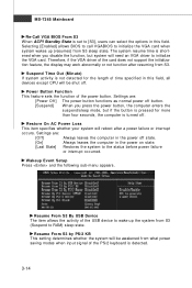
MS-7365 Mainboard Re-Call VGA BIOS From S3 W hen ACPI Standby State is set to [S3], users can select the options in this field, all devices except CPU will be awakened ... shut off state. [On] Always leaves the computer in the power off . Wakeup Event Setup Press and the following sub-menu appears. Selecting [Enabled] allows BIOS to call VGABIOS to initialize the VGA card. Restore On AC Power Loss This item specifies whether your system will need an VGA driver to...
MS-7365 Mainboard Re-Call VGA BIOS From S3 W hen ACPI Standby State is set to [S3], users can select the options in this field, all devices except CPU will be awakened ... shut off state. [On] Always leaves the computer in the power off . Wakeup Event Setup Press and the following sub-menu appears. Selecting [Enabled] allows BIOS to call VGABIOS to initialize the VGA card. Restore On AC Power Loss This item specifies whether your system will need an VGA driver to...
User Guide
Page 49
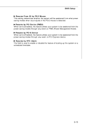
Resume by RTC Alarm The field is detected. BIOS Setup Resume From S3 by PS/2 Mouse This setting determines whether the system will be awakened from what power saving modes when input signal of ...
Resume by RTC Alarm The field is detected. BIOS Setup Resume From S3 by PS/2 Mouse This setting determines whether the system will be awakened from what power saving modes when input signal of ...


