User Guide
Page 4
... this User's Manual for further guidance. The openings on the enclosure are for technical guide, BIOS updates, driver updates, and other information: http://www.msi.com.tw & http://www.msi. Place the power cord such a way that could damage or cause electrical shock. 11. Always Unplug the Power Cord before setting it may damage the equipment. All cautions and warnings on card or...
... this User's Manual for further guidance. The openings on the enclosure are for technical guide, BIOS updates, driver updates, and other information: http://www.msi.com.tw & http://www.msi. Place the power cord such a way that could damage or cause electrical shock. 11. Always Unplug the Power Cord before setting it may damage the equipment. All cautions and warnings on card or...
User Guide
Page 5
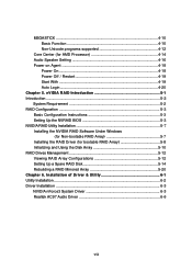
... Started 1-1 Mainboard Specifications 1-2 Mainboard Layout 1-4 Packing Contents 1-5 Chapter 2. Hardware Setup 2-1 Quick Components Guide 2-2 Central Processing Unit: CPU 2-2 CPU Installation Procedures for Socket 754 2-4 Installing AMD Athlon64 CPU Cooler Set 2-5 Memory ...2-7 Introduction to DDR SDRAM 2-7 DIMM Module Combination 2-7 Installing DDR Modules 2-8 Power Supply ...2-9 ATX 20-Pin Power Connector: JWR1 2-9 ATX 12V Power Connector: JPW1 2-9 Important Notification of Power Issue 2-10 Back Panel ...2-11 Mouse/Keyboard Connector 2-11 IEEE1394 Port (Optional 2-11 Serial...
... Started 1-1 Mainboard Specifications 1-2 Mainboard Layout 1-4 Packing Contents 1-5 Chapter 2. Hardware Setup 2-1 Quick Components Guide 2-2 Central Processing Unit: CPU 2-2 CPU Installation Procedures for Socket 754 2-4 Installing AMD Athlon64 CPU Cooler Set 2-5 Memory ...2-7 Introduction to DDR SDRAM 2-7 DIMM Module Combination 2-7 Installing DDR Modules 2-8 Power Supply ...2-9 ATX 20-Pin Power Connector: JWR1 2-9 ATX 12V Power Connector: JPW1 2-9 Important Notification of Power Issue 2-10 Back Panel ...2-11 Mouse/Keyboard Connector 2-11 IEEE1394 Port (Optional 2-11 Serial...
User Guide
Page 6
... First Boot Device 3-2 Control Keys 3-3 Getting Help 3-3 The Main Menu 3-4 Standard CMOS Features 3-6 Advanced BIOS Features 3-8 Advanced Chipset Features 3-11 Integrated Peripherals 3-12 Power Management Setup 3-17 PNP/PCI Configurations 3-20 H/W Monitor ...3-22 Cell Menu ...3-24 Load Fail-Safe/Optimized Defaults 3-28 Set Supervisor/User Password 3-29 Chapter 4. D-Bracket™ 2 Connector: JLED1 2-19 CD-In Connector: JCD1 2-20 Front Panel Audio Connector: JAUD1 2-20 IrDA Infrared Module Header: JIR1 2-21 Front USB Connectors: JUSB1 & JUSB2 2-21 Chassis Intrusion Switch...
... First Boot Device 3-2 Control Keys 3-3 Getting Help 3-3 The Main Menu 3-4 Standard CMOS Features 3-6 Advanced BIOS Features 3-8 Advanced Chipset Features 3-11 Integrated Peripherals 3-12 Power Management Setup 3-17 PNP/PCI Configurations 3-20 H/W Monitor ...3-22 Cell Menu ...3-24 Load Fail-Safe/Optimized Defaults 3-28 Set Supervisor/User Password 3-29 Chapter 4. D-Bracket™ 2 Connector: JLED1 2-19 CD-In Connector: JCD1 2-20 Front Panel Audio Connector: JAUD1 2-20 IrDA Infrared Module Header: JIR1 2-21 Front USB Connectors: JUSB1 & JUSB2 2-21 Chassis Intrusion Switch...
User Guide
Page 7
... Configuration Instructions 5-3 Setting Up the NVRAID BIOS 5-3 NVIDIA RAID Utility Installation 5-7 Installing the NVIDIA RAID Software Under Windows (for Non-bootable RAID Array 5-7 Installing the RAID Driver (for AMD Processor 4-14 Audio Speaker Setting 4-16 Power on Agent 4-18 Power On 4-18 Power Off / Restart 4-19 Start With 4-19 Auto Login 4-20 Chapter 5. MEGASTICK ...4-10 Basic Function 4-10 Non-Unicode programs supported 4-12 Core Center (for bootable RAID Array 5-8 Initializing and Using the Disk Array 5-10 RAID Drives Management 5-12 Viewing RAID Array Configurations...
... Configuration Instructions 5-3 Setting Up the NVRAID BIOS 5-3 NVIDIA RAID Utility Installation 5-7 Installing the NVIDIA RAID Software Under Windows (for Non-bootable RAID Array 5-7 Installing the RAID Driver (for AMD Processor 4-14 Audio Speaker Setting 4-16 Power on Agent 4-18 Power On 4-18 Power Off / Restart 4-19 Start With 4-19 Auto Login 4-20 Chapter 5. MEGASTICK ...4-10 Basic Function 4-10 Non-Unicode programs supported 4-12 Core Center (for bootable RAID Array 5-8 Initializing and Using the Disk Array 5-10 RAID Drives Management 5-12 Viewing RAID Array Configurations...
User Guide
Page 9
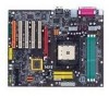
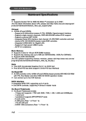
... ECC support. - Main Memory h Supports 3 slots for 184-pin DDR DIMM modules h Supports the memory size up to 3400+. (For the latest information about CPU, please visit http://www.msi.com.tw/program/ products/mainboard/mbd/pro_mbd_cpu_support.php) Chipset h nVIDIA nForce3 250Gb - Supports K8 Athlon64 processor S-754, 800MHz Hypertransport interface. - Supports external AGP 4X/8X - 7030 ATX Mainboard Mainboard Specifications CPU h Supports Socket-754 for AMD K8 Athlon™ processor up to 4 ports h One SATA controller, supporting 4 drives in master mode On-Board...
... ECC support. - Main Memory h Supports 3 slots for 184-pin DDR DIMM modules h Supports the memory size up to 3400+. (For the latest information about CPU, please visit http://www.msi.com.tw/program/ products/mainboard/mbd/pro_mbd_cpu_support.php) Chipset h nVIDIA nForce3 250Gb - Supports K8 Athlon64 processor S-754, 800MHz Hypertransport interface. - Supports external AGP 4X/8X - 7030 ATX Mainboard Mainboard Specifications CPU h Supports Socket-754 for AMD K8 Athlon™ processor up to 4 ports h One SATA controller, supporting 4 drives in master mode On-Board...
User Guide
Page 10
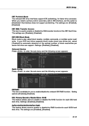
...(3 ports supported) NV RAID (Software) h Supports 2 serial ATA plus 1 ATA 133 - Getting Started LAN h nVIDIA nForce3 250Gb LAN controller - RAID 1, or 1, o+1, JBOD is required. Under these two OSs, SATA can only be created before attempting to the following website: http://www.microsoft.com/windows2000/downloads/ servicepacks/sp4/HFdeploy.htm 1-3 Supports ACPI Power Management. Booting from RAID - Spare Disk Allocation h Supports Windows 2000 and later versions BIOS h The mainboard BIOS provides "Plug & Play" BIOS which records your mainboard specifications. Cross controller RAID...
...(3 ports supported) NV RAID (Software) h Supports 2 serial ATA plus 1 ATA 133 - Getting Started LAN h nVIDIA nForce3 250Gb LAN controller - RAID 1, or 1, o+1, JBOD is required. Under these two OSs, SATA can only be created before attempting to the following website: http://www.microsoft.com/windows2000/downloads/ servicepacks/sp4/HFdeploy.htm 1-3 Supports ACPI Power Management. Booting from RAID - Spare Disk Allocation h Supports Windows 2000 and later versions BIOS h The mainboard BIOS provides "Plug & Play" BIOS which records your mainboard specifications. Cross controller RAID...
User Guide
Page 32
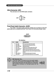
... the front audio header, pins 5 & 6, 9 & 10 have to be jumpered in order to have signal output directed to front panel 10 AUD_RET_L Left channel audio signal return from front panel 7 HP_ON Reserved for CD-ROM audio connector. Otherwise, the Line-Out connector on the back panel will not function. 6 10 59 2-20 MS-7030 ATX Mainboard CD-In Connector: JCD1 The connector is compliant with Intel® Front Panel I/O Connectivity Design Guide.
... the front audio header, pins 5 & 6, 9 & 10 have to be jumpered in order to have signal output directed to front panel 10 AUD_RET_L Left channel audio signal return from front panel 7 HP_ON Reserved for CD-ROM audio connector. Otherwise, the Line-Out connector on the back panel will not function. 6 10 59 2-20 MS-7030 ATX Mainboard CD-In Connector: JCD1 The connector is compliant with Intel® Front Panel I/O Connectivity Design Guide.

User Guide
Page 36
... D# pins as wireless LAN card. The orange PCI slot (PCI5) also works as a communication slot, which devices can send interrupt signals to meet your needs. AGP (Accelerated Graphics Port) Slot The AGP slot allows you to insert the expansion cards to the microprocessor. Meanwhile, read the documentation for the expansion card to make sure that you to directly access main memory. It introduces a 66MHz, 32-bit channel for the graphics controller...
... D# pins as wireless LAN card. The orange PCI slot (PCI5) also works as a communication slot, which devices can send interrupt signals to meet your needs. AGP (Accelerated Graphics Port) Slot The AGP slot allows you to insert the expansion cards to the microprocessor. Meanwhile, read the documentation for the expansion card to make sure that you to directly access main memory. It introduces a 66MHz, 32-bit channel for the graphics controller...
User Guide
Page 38
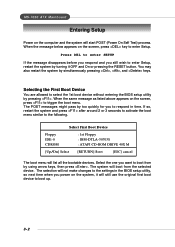
... boot menu similar to respond in time. Select First Boot Device Floppy IDE-0 CDROM : 1st Floppy : IBM-DTLA-307038 : ATAPI CD-ROM DRIVE 40X M [Up/Dn] Select [RETURN] Boot [ESC] cancel The boot menu will not make changes to the settings in the BIOS setup utility, so next time when you to the following. MS-7030 ATX Mainboard Entering Setup Power on the system, it OFF and On or pressing the RESET button. The system will boot...
... boot menu similar to respond in time. Select First Boot Device Floppy IDE-0 CDROM : 1st Floppy : IBM-DTLA-307038 : ATAPI CD-ROM DRIVE 40X M [Up/Dn] Select [RETURN] Boot [ESC] cancel The boot menu will not make changes to the settings in the BIOS setup utility, so next time when you to the following. MS-7030 ATX Mainboard Entering Setup Power on the system, it OFF and On or pressing the RESET button. The system will boot...
User Guide
Page 42
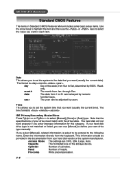
... hard disk will not work properly if you select [Manual], related information is not matched or listed, you can be entered to the following items. Enter the information directly from 1 to select [Manual], [None] or [Auto] type. MS-7030 ATX Mainboard Standard CMOS Features The items in Standard CMOS Features Menu includes some basic setup items. Use the arrow keys to highlight the item and then use [Manual] to define your own drive type manually...
... hard disk will not work properly if you select [Manual], related information is not matched or listed, you can be entered to the following items. Enter the information directly from 1 to select [Manual], [None] or [Auto] type. MS-7030 ATX Mainboard Standard CMOS Features The items in Standard CMOS Features Menu includes some basic setup items. Use the arrow keys to highlight the item and then use [Manual] to define your own drive type manually...
User Guide
Page 44
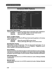
... to set the Virus Warning feature for IDE Hard Disk boot sector protection. Settings: [Enabled] and [Disabled]. Then you may use the arrow keys ( ↑↓ ) to select the desired device, then press , or , key to turn on or off CPU's external (L2) cache. Settings are : [Disabled] Shows the normal POST screen at boot. [Enabled] Shows a still image (EPA logo) on the screen at boot. MS-7030 ATX Mainboard Advanced BIOS Features Full Screen LOGO Display This item enables you...
... to set the Virus Warning feature for IDE Hard Disk boot sector protection. Settings: [Enabled] and [Disabled]. Then you may use the arrow keys ( ↑↓ ) to select the desired device, then press , or , key to turn on or off CPU's external (L2) cache. Settings are : [Disabled] Shows the normal POST screen at boot. [Enabled] Shows a still image (EPA logo) on the screen at boot. MS-7030 ATX Mainboard Advanced BIOS Features Full Screen LOGO Display This item enables you...
User Guide
Page 46
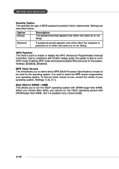
... Interrupt Controller). Settings: [Enabled], [Disabled]. But it is powered on or when end users try to run Setup. [System] A password prompt appears every time when the computer is possible if you to select which version to run Setup. Settings are described below: Option [Setup] Description The password prompt appears only when end users try to use, consult the vendor of BIOS password protection that is implemented. MS-7030 ATX Mainboard Security Option This...
... Interrupt Controller). Settings: [Enabled], [Disabled]. But it is powered on or when end users try to run Setup. [System] A password prompt appears every time when the computer is possible if you to select which version to run Setup. Settings are described below: Option [Setup] Description The password prompt appears only when end users try to use, consult the vendor of BIOS password protection that is implemented. MS-7030 ATX Mainboard Security Option This...
User Guide
Page 47
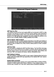
... AGP card supports the feature. However, if any translation. BIOS Setup Advanced Chipset Features AGP Aperture Size This setting controls just how much system RAM can be allocated to AGP for AGP 2.0 Speed: [1x], [1x2x], [1x2x4x]. Setting options for video purposes. The option allows the selection of an aperture size of the PCI memory address range dedicated to graphics memory address space. AGP Fast Write The item enables or disables the...
... AGP card supports the feature. However, if any translation. BIOS Setup Advanced Chipset Features AGP Aperture Size This setting controls just how much system RAM can be allocated to AGP for AGP 2.0 Speed: [1x], [1x2x], [1x2x4x]. Setting options for video purposes. The option allows the selection of an aperture size of the PCI memory address range dedicated to graphics memory address space. AGP Fast Write The item enables or disables the...
User Guide
Page 49
BIOS Setup IDE Prefetch Mode The onboard IDE drive interfaces support IDE prefetching, for each SATA hard disk drive. The settings are : [Enabled], [Disabled]. 3-13 If your IDE hard drive supports block mode (most new drives do), select [Enabled] for automatic detection of the optimal number of the IDE Hard Drive. Settings: [Enabled], [Disabled]. The settings are : [Enabled], [Disabled]. When you to enable/disable the onboard IDE RAID function. Settings: [Enabled], [Disabled]. IDE DMA Transfer Access This item is used to enter the sub-menu and the following screen appears: ...
BIOS Setup IDE Prefetch Mode The onboard IDE drive interfaces support IDE prefetching, for each SATA hard disk drive. The settings are : [Enabled], [Disabled]. 3-13 If your IDE hard drive supports block mode (most new drives do), select [Enabled] for automatic detection of the optimal number of the IDE Hard Drive. Settings: [Enabled], [Disabled]. The settings are : [Enabled], [Disabled]. When you to enable/disable the onboard IDE RAID function. Settings: [Enabled], [Disabled]. IDE DMA Transfer Access This item is used to enter the sub-menu and the following screen appears: ...
User Guide
Page 50
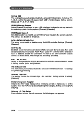
...an audio device is detected, the onboard AC'97 (Audio Codec'97) controller will be enabled; Onboard Giga LAN This setting controls the onboard Giga LAN controller. Primary Graphic's Adapter Initialize the AGP video display before initializing any other controller cards to connect an audio device. The settings are : [Enabled], [Disabled]. If an audio device is used. Setting options: [Enabled], [Disabled]. MS-7030 ATX Mainboard OnChip USB This setting allows you to enable or disable onchip Serial-ATA controller. Setting options: [Enabled], [Disabled]. Disable the controller...
...an audio device is detected, the onboard AC'97 (Audio Codec'97) controller will be enabled; Onboard Giga LAN This setting controls the onboard Giga LAN controller. Primary Graphic's Adapter Initialize the AGP video display before initializing any other controller cards to connect an audio device. The settings are : [Enabled], [Disabled]. If an audio device is used. Setting options: [Enabled], [Disabled]. MS-7030 ATX Mainboard OnChip USB This setting allows you to enable or disable onchip Serial-ATA controller. Setting options: [Enabled], [Disabled]. Disable the controller...
User Guide
Page 58
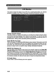
... set the field to [Enabled] later. NB/CPU Fan Tolerance (oC) You can control the fan speed automatically depending on the current temperature to keep it with CPU Fan. To clear the warning message, set here), the fans will slow down . Smart NB/CPU Fan Target There are 2 pairs of the 2 fans reach the maximum threshold (the temperatures set in a specific range. MS-7030 ATX Mainboard H/W Monitor This section shows the status of recording the chassis...
... set the field to [Enabled] later. NB/CPU Fan Tolerance (oC) You can control the fan speed automatically depending on the current temperature to keep it with CPU Fan. To clear the warning message, set here), the fans will slow down . Smart NB/CPU Fan Target There are 2 pairs of the 2 fans reach the maximum threshold (the temperatures set in a specific range. MS-7030 ATX Mainboard H/W Monitor This section shows the status of recording the chassis...
User Guide
Page 61
.... Setting options: [Disabled] Disable Dynamic Overclocking function. [Private] 1st level of cycles for normal mode CPU/FSB parameters. Available settings: [Auto], [2], [3], [4], [5], [6]. When [Enabled] is the automatic overclocking function, included in the MSITM's newly developed CoreCellTM Technology. When the motherboard detects CPU is designed to detect the load balance of data like 3D games or the video process, and the CPU frequency need to be allowed to enable or disable the memory clock. Setting options: [Auto...
.... Setting options: [Disabled] Disable Dynamic Overclocking function. [Private] 1st level of cycles for normal mode CPU/FSB parameters. Available settings: [Auto], [2], [3], [4], [5], [6]. When [Enabled] is the automatic overclocking function, included in the MSITM's newly developed CoreCellTM Technology. When the motherboard detects CPU is designed to detect the load balance of data like 3D games or the video process, and the CPU frequency need to be allowed to enable or disable the memory clock. Setting options: [Auto...
User Guide
Page 62
... frequency. MS-7030 ATX Mainboard [Sergeant] [Captain] [Colonel] [General] [Commander] 2nd level of overclocking, increasing the CPU frequency by 3%. 3rd level of overclocking, also the default value of "Load High Performance Defaults", increasing the CPU frequency by 5%. 4th level of overclocking, increasing the CPU frequency by 7%. 5th level of overclocking, increasing the CPU frequency by 9%. 6th level of the link's transmitter clock. Even though the Dynamic Overclocking Technology is always recommended to have the memories plugged...
... frequency. MS-7030 ATX Mainboard [Sergeant] [Captain] [Colonel] [General] [Commander] 2nd level of overclocking, increasing the CPU frequency by 3%. 3rd level of overclocking, also the default value of "Load High Performance Defaults", increasing the CPU frequency by 5%. 4th level of overclocking, increasing the CPU frequency by 7%. 5th level of overclocking, increasing the CPU frequency by 9%. 6th level of the link's transmitter clock. Even though the Dynamic Overclocking Technology is always recommended to have the memories plugged...
User Guide
Page 74
.... Updates the VGA driver online. Updates the utilities online. Updates the BIOS online. Live Driver - Updates the firmware of the functions listed above, a "sorry" message is displayed. For more information on the Live Update icon in the main menu and the Live Update program will be enabled. Introduction to DigiCell Live Update Click on the update instructions, insert the companion CD and refer to the "Live Update Guide" under the "Manual" Tab. 4-9 Live Utility...
.... Updates the VGA driver online. Updates the utilities online. Updates the BIOS online. Live Driver - Updates the firmware of the functions listed above, a "sorry" message is displayed. For more information on the Live Update icon in the main menu and the Live Update program will be enabled. Introduction to DigiCell Live Update Click on the update instructions, insert the companion CD and refer to the "Live Update Guide" under the "Manual" Tab. 4-9 Live Utility...
User Guide
Page 93
... instruction below : MSI Reminds You... Specify the NVIDIA drivers: (1) Insert the floppy that has the RAID driver, press S, then press Enter. Insert the MSI CD into the CD-ROM drive. 2. After you complete the RAID BIOS setup, boot from the Windows CD, and the Windows Setup program starts. 2. Press F6 and wait for nVIDIA Serial ATA driver is done. (2) Select "NVIDIA RAID CLASS DRIVER" and then press Enter. (3) Press S again at the Specify Devices screen...
... instruction below : MSI Reminds You... Specify the NVIDIA drivers: (1) Insert the floppy that has the RAID driver, press S, then press Enter. Insert the MSI CD into the CD-ROM drive. 2. After you complete the RAID BIOS setup, boot from the Windows CD, and the Windows Setup program starts. 2. Press F6 and wait for nVIDIA Serial ATA driver is done. (2) Select "NVIDIA RAID CLASS DRIVER" and then press Enter. (3) Press S again at the Specify Devices screen...


