User Guide
Page 5
CONTENTS FCC-B Radio Frequency Interference Statement ii Copyright Notice ...iii Revision History ...iii Safety Instructions ...iv Technical Support ...iv Chapter 1. Getting Started 1-1 Mainboard Specifications 1-2 Mainboard Layout 1-4 Packing Contents 1-5 Chapter 2. Hardware Setup 2-1 Quick Components Guide 2-2 Central Processing Unit: CPU 2-2 CPU Installation Procedures for Socket 754 2-4 Installing AMD Athlon64 CPU Cooler Set 2-5 ...
CONTENTS FCC-B Radio Frequency Interference Statement ii Copyright Notice ...iii Revision History ...iii Safety Instructions ...iv Technical Support ...iv Chapter 1. Getting Started 1-1 Mainboard Specifications 1-2 Mainboard Layout 1-4 Packing Contents 1-5 Chapter 2. Hardware Setup 2-1 Quick Components Guide 2-2 Central Processing Unit: CPU 2-2 CPU Installation Procedures for Socket 754 2-4 Installing AMD Athlon64 CPU Cooler Set 2-5 ...
User Guide
Page 8
Getting Started Getting Started Thank you for optimal system efficiency. The K8N Neo Platinum mainboard is based on nVIDIA® nForce™3 250Gb chipset for choosing the K8N Neo Platinum (MS-7030) v1.X ATX mainboard. Designed to fit the advanced AMD® K8 Athlon 64 processor, the K8N Neo Platinum mainboard delivers a high performance and professional desktop platform solution. 1-1 Getting Started Chapter 1.
Getting Started Getting Started Thank you for optimal system efficiency. The K8N Neo Platinum mainboard is based on nVIDIA® nForce™3 250Gb chipset for choosing the K8N Neo Platinum (MS-7030) v1.X ATX mainboard. Designed to fit the advanced AMD® K8 Athlon 64 processor, the K8N Neo Platinum mainboard delivers a high performance and professional desktop platform solution. 1-1 Getting Started Chapter 1.
User Guide
Page 9
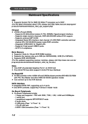
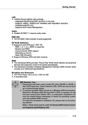
... 3GB (for AMD K8 Athlon™ processor up to 3400+. (For the latest information about CPU, please visit http://www.msi.com.tw/program/ products/mainboard/mbd/pro_mbd_cpu_support.php) Chipset h nVIDIA nForce3 250Gb - Supports 8 high speed USB2.0 ports. - h Supports DDR 400/333/...2.3 compliance. Supports single memory channels, DDR 400/333/266 without ECC support. - Supports K8 Athlon64 processor S-754, 800MHz Hypertransport interface. - 7030 ATX Mainboard Mainboard Specifications CPU h Supports Socket-754 for DDR333/266) / 2GB (For DDR400) . Integrated nVIDIA MAC for Gigabit LAN. -
... 3GB (for AMD K8 Athlon™ processor up to 3400+. (For the latest information about CPU, please visit http://www.msi.com.tw/program/ products/mainboard/mbd/pro_mbd_cpu_support.php) Chipset h nVIDIA nForce3 250Gb - Supports 8 high speed USB2.0 ports. - h Supports DDR 400/333/...2.3 compliance. Supports single memory channels, DDR 400/333/266 without ECC support. - Supports K8 Athlon64 processor S-754, 800MHz Hypertransport interface. - 7030 ATX Mainboard Mainboard Specifications CPU h Supports Socket-754 for DDR333/266) / 2GB (For DDR400) . Integrated nVIDIA MAC for Gigabit LAN. -
User Guide
Page 10
... Supports 2 serial ATA plus 1 ATA 133 - Mounting and Dimension h ATX Form Factor: 24.4 cm (L) x 30.5 cm (W) h 9 mounting holes MSI Reminds You... 1. As the end user cannot boot without SP4, a combination installation CD must be used as a normal storage device. 2. Supports ACPI Power ...Management. h The mainboard provides a Desktop Management Interface (DMI) function which detects the peripheral devices and expansion cards of the board automatically. Spare Disk Allocation...
... Supports 2 serial ATA plus 1 ATA 133 - Mounting and Dimension h ATX Form Factor: 24.4 cm (L) x 30.5 cm (W) h 9 mounting holes MSI Reminds You... 1. As the end user cannot boot without SP4, a combination installation CD must be used as a normal storage device. 2. Supports ACPI Power ...Management. h The mainboard provides a Desktop Management Interface (DMI) function which detects the peripheral devices and expansion cards of the board automatically. Spare Disk Allocation...
User Guide
Page 11
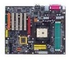
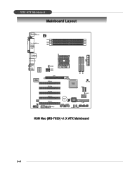
7030 ATX Mainboard Mainboard Layout Top : mouse Bottom: keyboard Top : Parallel Port Bottom: COM A 1394 Port SPDIF JPW1 DDR3 DDR2 DDR1 T: LAN jack B: USB ports B: USB ports T:Line-In M:Line-Out B:Mic T:RS-Out M:CS-Out B:SPDIFOut C_ FA N1 S ATA 3 S ATA 4 88E1111-RC VIA VT6306 AGP1 PCI Slot 1 PCI Slot2 PCI Slot3 PCI Slot 4 ALC 850 JCD1 JAUD1 J1394_1 PCI Slot 5 J1394_0 nForce3 250Gb NB_FAN1 S ATA 2 JCASE1 B AT T + J BAT 1 J IR 1 JUSB1 JUSB2 BIOS Winbond W83627HF FDD 1 JLED1 JFP1 JFP2 S_FAN2 S_FAN1 IDE 2 IDE 1 JWR1 K8N Neo (MS-7030) v1.X ATX Mainboard 1-4
7030 ATX Mainboard Mainboard Layout Top : mouse Bottom: keyboard Top : Parallel Port Bottom: COM A 1394 Port SPDIF JPW1 DDR3 DDR2 DDR1 T: LAN jack B: USB ports B: USB ports T:Line-In M:Line-Out B:Mic T:RS-Out M:CS-Out B:SPDIFOut C_ FA N1 S ATA 3 S ATA 4 88E1111-RC VIA VT6306 AGP1 PCI Slot 1 PCI Slot2 PCI Slot3 PCI Slot 4 ALC 850 JCD1 JAUD1 J1394_1 PCI Slot 5 J1394_0 nForce3 250Gb NB_FAN1 S ATA 2 JCASE1 B AT T + J BAT 1 J IR 1 JUSB1 JUSB2 BIOS Winbond W83627HF FDD 1 JLED1 JFP1 JFP2 S_FAN2 S_FAN1 IDE 2 IDE 1 JWR1 K8N Neo (MS-7030) v1.X ATX Mainboard 1-4

User Guide
Page 13
While doing the installation, be careful in holding the components and follow the installation procedures. 2-1 Also, it provides the instructions on the mainboard. Hardware Setup Hardware Setup This chapter tells you how to install the CPU, memory modules, and expansion cards, as well as how to setup the jumpers on connecting the peripheral devices, such as the mouse, keyboard, etc. Hardware Setup Chapter 2.
While doing the installation, be careful in holding the components and follow the installation procedures. 2-1 Also, it provides the instructions on the mainboard. Hardware Setup Hardware Setup This chapter tells you how to install the CPU, memory modules, and expansion cards, as well as how to setup the jumpers on connecting the peripheral devices, such as the mouse, keyboard, etc. Hardware Setup Chapter 2.
User Guide
Page 15
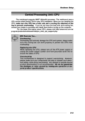
....tw/ program/products/mainboard/mbd/pro_mbd_cpu_support.php. When you do not guarantee the damages or risks caused by inadequate operation or beyond product specifications is designed to ensure the safety of CPU. Overclocking This motherboard is not recommended. MSI Reminds You... We do not have the heat sink and cooling fan, contact your...
....tw/ program/products/mainboard/mbd/pro_mbd_cpu_support.php. When you do not guarantee the damages or risks caused by inadequate operation or beyond product specifications is designed to ensure the safety of CPU. Overclocking This motherboard is not recommended. MSI Reminds You... We do not have the heat sink and cooling fan, contact your...
User Guide
Page 16
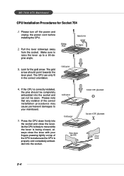
...into the socket. 2-4 As the CPU is likely to move while the lever is correctly installed, the pins should point towards the lever pivot. MS-7030 ATX Mainboard CPU Installation Procedures for the gold arrow. Press the CPU down firmly into the socket and can only fit in the correct orientation. 4. The... gold arrow should be completely embedded into the socket and close the lever with your mainboard. 5. The CPU can not be seen. If the CPU is being closed, always close the lever. Please turn off the power and unplug ...
...into the socket. 2-4 As the CPU is likely to move while the lever is correctly installed, the pins should point towards the lever pivot. MS-7030 ATX Mainboard CPU Installation Procedures for the gold arrow. Press the CPU down firmly into the socket and can only fit in the correct orientation. 4. The... gold arrow should be completely embedded into the socket and close the lever with your mainboard. 5. The CPU can not be seen. If the CPU is being closed, always close the lever. Please turn off the power and unplug ...

User Guide
Page 17
Fix the retention mechanism and the backplate with two screws. Turn over the mainboard, and install the backplate to the proper position. 4. Locate the two screw holes of the backplate's paster. 3. retention mechanism 2-5 If you are installing the CPU, ...make sure the CPU has a heat sink and a cooling fan attached on the top to prevent overheating. Turn over the mainboard again and place the mainboard on the flat surface. Hardware Setup Installing AMD Athlon64 CPU Cooler Set When you do not have the heat sink and cooling fan...
Fix the retention mechanism and the backplate with two screws. Turn over the mainboard, and install the backplate to the proper position. 4. Locate the two screw holes of the backplate's paster. 3. retention mechanism 2-5 If you are installing the CPU, ...make sure the CPU has a heat sink and a cooling fan attached on the top to prevent overheating. Turn over the mainboard again and place the mainboard on the flat surface. Hardware Setup Installing AMD Athlon64 CPU Cooler Set When you do not have the heat sink and cooling fan...
User Guide
Page 18
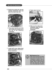
... lever will spring back instantly. Press down the lever. 6. Safety Hook Fixed Lever Fixed Bolt 2-6 MSI Reminds You... Fasten down the other end of the retention mechanism. 9. Hook one end of the retention mechanism. 7. MS-7030 ATX Mainboard 5. Position the cooling set on the top of the clip to keep an eye on your...
... lever will spring back instantly. Press down the lever. 6. Safety Hook Fixed Lever Fixed Bolt 2-6 MSI Reminds You... Fasten down the other end of the retention mechanism. 9. Hook one end of the retention mechanism. 7. MS-7030 ATX Mainboard 5. Position the cooling set on the top of the clip to keep an eye on your...

User Guide
Page 19
...tw/program/products/mainboard/mbd/pro_mbd_trp_list.php. You can install DDR266/333/400 modules on the DDR DIMM slots (DDR 1~3). The plastic clip at each side of module. You can barely see the golden finger if the module is deeply inserted in the socket. 3. Volt Notch MSI Reminds You... ...Hardware Setup Memory The mainboard provides 3 slots for 184-pin DDR SDRAM DIMM (Double InLine Memory Module) modules and supports the memory size up to 3GB...
...tw/program/products/mainboard/mbd/pro_mbd_trp_list.php. You can install DDR266/333/400 modules on the DDR DIMM slots (DDR 1~3). The plastic clip at each side of module. You can barely see the golden finger if the module is deeply inserted in the socket. 3. Volt Notch MSI Reminds You... ...Hardware Setup Memory The mainboard provides 3 slots for 184-pin DDR SDRAM DIMM (Double InLine Memory Module) modules and supports the memory size up to 3GB...

User Guide
Page 21
... ATX power supply for system stability. 2-9 Then push down the power supply firmly into the connector. Power supply of the mainboard. 2. ATX 20-Pin Power Connector: JWR1 This connector allows you to connect to the ATX power supply, make sure that no damage will be caused. ... 12V 20 SIGNAL 3.3V -12V GND PS_ON GND GND GND -5V 5V 5V 13 24 JPW1 JPW1 Pin Definition PIN SIGNAL 1 GND 2 GND 3 12V 4 12V MSI Reminds You... 1. Before inserting the power supply connector, always make sure the plug of the power supply is used to provide power to ensure that...
... ATX power supply for system stability. 2-9 Then push down the power supply firmly into the connector. Power supply of the mainboard. 2. ATX 20-Pin Power Connector: JWR1 This connector allows you to connect to the ATX power supply, make sure that no damage will be caused. ... 12V 20 SIGNAL 3.3V -12V GND PS_ON GND GND GND -5V 5V 5V 13 24 JPW1 JPW1 Pin Definition PIN SIGNAL 1 GND 2 GND 3 12V 4 12V MSI Reminds You... 1. Before inserting the power supply connector, always make sure the plug of the power supply is used to provide power to ensure that...
User Guide
Page 22
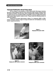
... this issue mostly happens while the users intensively swap memory modules under S5 (power-off) states, and the power code is very sensitive to boot. MS-7030 ATX Mainboard Important Notification about Power Issue NForce chipset is plugged while installing modules. Unplug the AC power cable (shown in figure 1) or unplug the JWR1...
... this issue mostly happens while the users intensively swap memory modules under S5 (power-off) states, and the power code is very sensitive to boot. MS-7030 ATX Mainboard Important Notification about Power Issue NForce chipset is plugged while installing modules. Unplug the AC power cable (shown in figure 1) or unplug the JWR1...

User Guide
Page 23
...: Mouse Parallel LAN Hardware Setup L-In RS-Out Keyboard COM A 1394 Port S/PDIF USB Ports L-Out CS-Out Mic SPDIF Out Mouse/Keyboard Connector The mainboard provides a standard PS/2® mouse/keyboard mini DIN connector for a wide range of devices, including consumer electronics audio/video (A/V) appliances, storage peripherals, other PCs, and...
...: Mouse Parallel LAN Hardware Setup L-In RS-Out Keyboard COM A 1394 Port S/PDIF USB Ports L-Out CS-Out Mic SPDIF Out Mouse/Keyboard Connector The mainboard provides a standard PS/2® mouse/keyboard mini DIN connector for a wide range of devices, including consumer electronics audio/video (A/V) appliances, storage peripherals, other PCs, and...
User Guide
Page 24
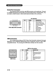
...Positive Data Channel 0 Ground +5V Negative Data Channel 1 Positive Data Channel 1 Ground 2-12 You can attach a serial mouse or other USBcompatible devices. MS-7030 ATX Mainboard Serial Port Connector The mainboard offers one 9-pin male DIN connector as keyboard, mouse or other serial devices directly to the connector. 1 2 3 4 5 PIN 1 2 3... Data Data Terminal Ready) Ground Data Set Ready Request To Send Clear To Send Ring Indicate USB Connectors The mainboard provides an OHCI (Open Host Controller Interface) Universal Serial Bus root for attaching USB devices such as the serial...
...Positive Data Channel 0 Ground +5V Negative Data Channel 1 Positive Data Channel 1 Ground 2-12 You can attach a serial mouse or other USBcompatible devices. MS-7030 ATX Mainboard Serial Port Connector The mainboard offers one 9-pin male DIN connector as keyboard, mouse or other serial devices directly to the connector. 1 2 3 4 5 PIN 1 2 3... Data Data Terminal Ready) Ground Data Set Ready Request To Send Clear To Send Ring Indicate USB Connectors The mainboard provides an OHCI (Open Host Controller Interface) Universal Serial Bus root for attaching USB devices such as the serial...

User Guide
Page 25
... 2-channel to 4-/5.1-channel audio. However, there is used for external CD player, Tape player, or other audio devices. Hardware Setup LAN (RJ-45) Jack The mainboard provides 1 standard RJ-45 jack for 7.1-channel audio operation and can connect a network cable to be transferred at 1000, 100 or 10Mbps. RJ-45 LAN...
... 2-channel to 4-/5.1-channel audio. However, there is used for external CD player, Tape player, or other audio devices. Hardware Setup LAN (RJ-45) Jack The mainboard provides 1 standard RJ-45 jack for 7.1-channel audio operation and can connect a network cable to be transferred at 1000, 100 or 10Mbps. RJ-45 LAN...
User Guide
Page 26
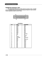
MS-7030 ATX Mainboard Parallel Port Connector: LPT1 The mainboard provides a 25-pin female centronic connector as LPT. A parallel port is a standard printer port that supports Enhanced Parallel Port (EPP) and Extended Capabilities Parallel Port (...
MS-7030 ATX Mainboard Parallel Port Connector: LPT1 The mainboard provides a 25-pin female centronic connector as LPT. A parallel port is a standard printer port that supports Enhanced Parallel Port (EPP) and Extended Capabilities Parallel Port (...

User Guide
Page 27
...1.44M and 2.88M floppy disk types. It supports three-pin head connector. C_FAN1 supports the fan control. Floppy Disk Drive Connector: FDD1 The mainboard provides a standard floppy disk drive connector that will automatically control the CPU fan speed according to GND. GND +12V SENSOR C_FAN1 GND +12V ...NC S_FAN1 GND +12V NC S_FAN2 GND +12V Sensor NB_FAN1 MSI Reminds You... 1. FDD1 Fan Power Connectors: C_FAN1/S_FAN1/S_FAN2/NB_FAN1 The C_FAN1 (processor fan), S_FAN1 (system fan 1), S_FAN2 (system fan 2) ...
...1.44M and 2.88M floppy disk types. It supports three-pin head connector. C_FAN1 supports the fan control. Floppy Disk Drive Connector: FDD1 The mainboard provides a standard floppy disk drive connector that will automatically control the CPU fan speed according to GND. GND +12V SENSOR C_FAN1 GND +12V ...NC S_FAN1 GND +12V NC S_FAN2 GND +12V Sensor NB_FAN1 MSI Reminds You... 1. FDD1 Fan Power Connectors: C_FAN1/S_FAN1/S_FAN2/NB_FAN1 The C_FAN1 (processor fan), S_FAN1 (system fan 1), S_FAN2 (system fan 2) ...

User Guide
Page 28
... setting the jumper accordingly. You must configure the second drive to Slave mode by setting its jumper. MSI Reminds You... IDE1 can also connect a Master and a Slave drive. MS-7030 ATX Mainboard Hard Disk Connectors: IDE1 & IDE2 The mainboard has a 32-bit Enhanced PCI IDE and Ultra DMA 33/66/100/133 controller that provides...
... setting the jumper accordingly. You must configure the second drive to Slave mode by setting its jumper. MSI Reminds You... IDE1 can also connect a Master and a Slave drive. MS-7030 ATX Mainboard Hard Disk Connectors: IDE1 & IDE2 The mainboard has a 32-bit Enhanced PCI IDE and Ultra DMA 33/66/100/133 controller that provides...

User Guide
Page 29
... ATA connector can connect to the Chapter 5: nVIDIA RAID Introduction for detail software installation procedure. Each supports 1st generation serial ATA data rates of this mainboard is nForce3 250Gb which will cause the loss of data during the transmission. 2-17 Please do not fold the serial ATA cable in a 90-degree... PIN SIGNAL 2 TXP 4 GND 6 RXP Serial ATA cable Connect to serial ATA ports Take out the dust cover and connect to the hard disk devices MSI Reminds You...
... ATA connector can connect to the Chapter 5: nVIDIA RAID Introduction for detail software installation procedure. Each supports 1st generation serial ATA data rates of this mainboard is nForce3 250Gb which will cause the loss of data during the transmission. 2-17 Please do not fold the serial ATA cable in a 90-degree... PIN SIGNAL 2 TXP 4 GND 6 RXP Serial ATA cable Connect to serial ATA ports Take out the dust cover and connect to the hard disk devices MSI Reminds You...


