
User's Guide
Page 33
Load the stack toward the rear of the tray as shown. Straighten the edges on a level surface. 5 Load the paper stack with the recommended print side faceup. When loading preprinted letterhead, place the header toward the back of the tray. 33 This second illustration shows the tabs, the size indicators, and the load line for the optional 530-sheet tray. 4 Flex the sheets back and forth to loosen them, and then fan them. Do not fold or crease the paper.
Load the stack toward the rear of the tray as shown. Straighten the edges on a level surface. 5 Load the paper stack with the recommended print side faceup. When loading preprinted letterhead, place the header toward the back of the tray. 33 This second illustration shows the tabs, the size indicators, and the load line for the optional 530-sheet tray. 4 Flex the sheets back and forth to loosen them, and then fan them. Do not fold or crease the paper.
User's Guide
Page 41
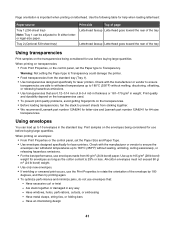
...Have an interlocking design 41 Using envelopes You can be adjusted to prevent sheets from sticking together. • We recommend Lexmark part number 12A8240 for letter-size and Lexmark part number 12A8241 for A4-size transparencies. All-cotton envelopes must not exceed 90 g/ m2 (24 lb bond) weight... Paper type to 105 g/m2 (28 lb bond) weight for laser printers. Print samples on the transparencies. • Before loading transparencies, fan the stack to fit either letteror legal-size paper. Print quality and durability depend on the transparencies used. • To prevent print quality ...
...Have an interlocking design 41 Using envelopes You can be adjusted to prevent sheets from sticking together. • We recommend Lexmark part number 12A8240 for letter-size and Lexmark part number 12A8241 for A4-size transparencies. All-cotton envelopes must not exceed 90 g/ m2 (24 lb bond) weight... Paper type to 105 g/m2 (28 lb bond) weight for laser printers. Print samples on the transparencies. • Before loading transparencies, fan the stack to fit either letteror legal-size paper. Print quality and durability depend on the transparencies used. • To prevent print quality ...

User's Guide
Page 71
For more information, see the Card Stock & Label Guide available on the Lexmark Web site at www.lexmark.com/publications. • Do not load too much paper. Clearing jams Avoiding jams The following hints can help you must clear all printer cables are ... documentation. Make sure the stack height does not exceed the indicated maximum height. • Do not load wrinkled, creased, damp, or curled paper. • Flex, fan, and straighten paper before loading it. • Do not use paper that has been cut or trimmed by hand. • Do not mix paper sizes...
For more information, see the Card Stock & Label Guide available on the Lexmark Web site at www.lexmark.com/publications. • Do not load too much paper. Clearing jams Avoiding jams The following hints can help you must clear all printer cables are ... documentation. Make sure the stack height does not exceed the indicated maximum height. • Do not load wrinkled, creased, damp, or curled paper. • Flex, fan, and straighten paper before loading it. • Do not use paper that has been cut or trimmed by hand. • Do not mix paper sizes...
Service Manual
Page 3
... Symptom tables 2-11 MFP symptom table 2-11 Print quality symptom table 2-13 Printer service checks 2-14 Main motor service check 2-14 CPU fan service check 2-16 Developer drive assembly service check 2-16 Transfer belt unit service check 2-17 Transfer roller clutch service check 2-18 Transfer belt... 2-19 Registration clutch service check 2-19 OPC belt marker sensor service check 2-20 Erase lamp service check 2-21 Power supply fan service check 2-22 Fuser fan service check 2-22 High voltage power supply (HVPS) service check 2-23 Low voltage power supply (LVPS) service check 2-23...
... Symptom tables 2-11 MFP symptom table 2-11 Print quality symptom table 2-13 Printer service checks 2-14 Main motor service check 2-14 CPU fan service check 2-16 Developer drive assembly service check 2-16 Transfer belt unit service check 2-17 Transfer roller clutch service check 2-18 Transfer belt... 2-19 Registration clutch service check 2-19 OPC belt marker sensor service check 2-20 Erase lamp service check 2-21 Power supply fan service check 2-22 Fuser fan service check 2-22 High voltage power supply (HVPS) service check 2-23 Low voltage power supply (LVPS) service check 2-23...
Service Manual
Page 6
... removals 4-46 Marker sensor assembly removal 4-46 Waste toner auger removal 4-47 Waste toner agitator removal 4-47 Power supply fan removal 4-48 Scanner assembly removals 4-49 Flatbed assembly removal 4-49 Scanner arm removal 4-52 ADF unit removal 4-53 ADF...and connectors 5-1 Printer front and rear views 5-1 Scanner locations 5-3 Electronic components 5-4 Printer engine sensor locations 5-4 MFP circuit board locations 5-5 Fan/motor and interlock switch locations 5-6 Clutch locations 5-7 Symbol and part name table 5-8 Engine controller board wiring diagram 5-9 RIP board 5-15...
... removals 4-46 Marker sensor assembly removal 4-46 Waste toner auger removal 4-47 Waste toner agitator removal 4-47 Power supply fan removal 4-48 Scanner assembly removals 4-49 Flatbed assembly removal 4-49 Scanner arm removal 4-52 ADF unit removal 4-53 ADF...and connectors 5-1 Printer front and rear views 5-1 Scanner locations 5-3 Electronic components 5-4 Printer engine sensor locations 5-4 MFP circuit board locations 5-5 Fan/motor and interlock switch locations 5-6 Clutch locations 5-7 Symbol and part name table 5-8 Engine controller board wiring diagram 5-9 RIP board 5-15...

Service Manual
Page 42
... clutch cable connection or a shorted or cut cable. Improper registration clutch cable connection or a shorted or cut cable. Improper fan motor rotation, improper fan motor cable connection or a shorted or cut cable. See "Low voltage power supply (LVPS) service check" on page 2-24.... See "Fuser assembly service check" on page 2-21. Improper erase lamp cable connection or a shorted or cut cable. Improper fan motor rotation, improper fan motor cable connection or a shorted or cut . See "Erase lamp service check" on page 2-24. 2-4 Service Manual Output ...
... clutch cable connection or a shorted or cut cable. Improper registration clutch cable connection or a shorted or cut cable. Improper fan motor rotation, improper fan motor cable connection or a shorted or cut cable. See "Low voltage power supply (LVPS) service check" on page 2-24.... See "Fuser assembly service check" on page 2-21. Improper erase lamp cable connection or a shorted or cut cable. Improper fan motor rotation, improper fan motor cable connection or a shorted or cut . See "Erase lamp service check" on page 2-24. 2-4 Service Manual Output ...
Service Manual
Page 48
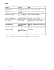
...page 2-16. Note: The expected yield of Memory Scan Memory Full Communication Error Server Connection Failed (TX / RX) Comm Error CPU fan locked Description Action The USB connection is disconnected. Contact the network administrator. device. The network connection is Break the scan job into smaller... segments. full. Break it up if needed . There is no longer See "CPU fan service check" on page 2-40. The CPU fan is a data transmission or reception error. Retry the job. device. Break it up if needed . disconnected. Memory...
...page 2-16. Note: The expected yield of Memory Scan Memory Full Communication Error Server Connection Failed (TX / RX) Comm Error CPU fan locked Description Action The USB connection is disconnected. Contact the network administrator. device. The network connection is Break the scan job into smaller... segments. full. Break it up if needed . There is no longer See "CPU fan service check" on page 2-40. The CPU fan is a data transmission or reception error. Retry the job. device. Break it up if needed . disconnected. Memory...

Service Manual
Page 49
..." on page 2-42. See "ADF paper feed service check" on page 2-3. Check the scanner lock switch. No power Waste toner feed problems Fans not working or making noise. Streaks down the middle of a copy, fax or scan when using the ADF Scanner locked Scanner fails to feed ... doors are closed. Paper fails to communicate with sending fax machine. See "Developer drive assembly service check" on page 2-13. Find the failing fan, and follow the action suggested. Diagnostic information 2-11 Developer motor makes noise or continuously runs. Black copies from the flatbed. See "Print quality ...
..." on page 2-42. See "ADF paper feed service check" on page 2-3. Check the scanner lock switch. No power Waste toner feed problems Fans not working or making noise. Streaks down the middle of a copy, fax or scan when using the ADF Scanner locked Scanner fails to feed ... doors are closed. Paper fails to communicate with sending fax machine. See "Developer drive assembly service check" on page 2-13. Find the failing fan, and follow the action suggested. Diagnostic information 2-11 Developer motor makes noise or continuously runs. Black copies from the flatbed. See "Print quality ...
Service Manual
Page 52
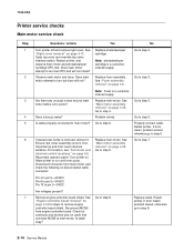
... MCN5 from main motor, and check the following on page 5-6. Open top cover and override top cover interlock switch. Replace fuser assembly. For location, see "Fan/motor and interlock switch locations" on disconnected cable connector: Note: Fuser is shut. See "Main motor assembly removal" on cable that connects MCN5 to step...
... MCN5 from main motor, and check the following on page 5-6. Open top cover and override top cover interlock switch. Replace fuser assembly. For location, see "Fan/motor and interlock switch locations" on disconnected cable connector: Note: Fuser is shut. See "Main motor assembly removal" on cable that connects MCN5 to step...

Service Manual
Page 54
...RIP board? Replace cable. If error clears, problem solved, otherwise go away? 7100-XXX CPU fan service check Step 1 2 Questions / actions Open the RIP cage cover. Is the CPU fan cable properly connected to J-Fan1 on page 5-6. Developer drive assembly service check No Go to step ...error posts. Turn printer off, and remove right cover. If waste toner bottle is shut. Remove engine controller board shield. Is the CPU fan spinning? Problem solved. See "Right cover removal" on . Disconnect connector from engine controller board. Connect the cable to fix. Yes No...
...RIP board? Replace cable. If error clears, problem solved, otherwise go away? 7100-XXX CPU fan service check Step 1 2 Questions / actions Open the RIP cage cover. Is the CPU fan cable properly connected to J-Fan1 on page 5-6. Developer drive assembly service check No Go to step ...error posts. Turn printer off, and remove right cover. If waste toner bottle is shut. Remove engine controller board shield. Is the CPU fan spinning? Problem solved. See "Right cover removal" on . Disconnect connector from engine controller board. Connect the cable to fix. Yes No...

Service Manual
Page 60
... page 4-34 for continuity and pin shorts. Check cable for steps to obtain ground.) Is voltage present and correct? See "Power supply fan removal" on page 5-6. See "Engine controller board removal" on , and check for 24VDC between engine controller board MCN10 pin 1 and ... 2. Turn printer off , and remove engine controller board shield. Is cable okay? Go to engine controller board connector MCN10? Replace power supply fan assembly. If error clears, problem solved, otherwise go to step 3. Replace engine controller board. See "Engine controller board removal" on page ...
... page 4-34 for continuity and pin shorts. Check cable for steps to obtain ground.) Is voltage present and correct? See "Power supply fan removal" on page 5-6. See "Engine controller board removal" on , and check for 24VDC between engine controller board MCN10 pin 1 and ... 2. Turn printer off , and remove engine controller board shield. Is cable okay? Go to engine controller board connector MCN10? Replace power supply fan assembly. If error clears, problem solved, otherwise go to step 3. Replace engine controller board. See "Engine controller board removal" on page ...

Service Manual
Page 73
... ohmmeter, check switches. Are any cables defective? See "Low voltage power supply (LVPS) with bracket" on page 4-21 for front interlock switch, see "Power supply fan removal" on page 4-48 for rear cover interlock switch. Actuator is infinite. See "Engine controller board removal" on page 4-40. Check for proper operation. Go...
... ohmmeter, check switches. Are any cables defective? See "Low voltage power supply (LVPS) with bracket" on page 4-21 for front interlock switch, see "Power supply fan removal" on page 4-48 for rear cover interlock switch. Actuator is infinite. See "Engine controller board removal" on page 4-40. Check for proper operation. Go...

Service Manual
Page 76
...? Go to step 6. See "Engine controller board removal" on page 4-36. Problem solved. Step 1 2 3 4 5 6 7 Questions / actions Yes No Reset printer, and listen for power supply fan. See "System board removal" on page 4-34. Using an ohmmeter, ensure power switch is installed, disconnect or remove before checking base printer operation. See "Low...
...? Go to step 6. See "Engine controller board removal" on page 4-36. Problem solved. Step 1 2 3 4 5 6 7 Questions / actions Yes No Reset printer, and listen for power supply fan. See "System board removal" on page 4-34. Using an ohmmeter, ensure power switch is installed, disconnect or remove before checking base printer operation. See "Low...
Service Manual
Page 141
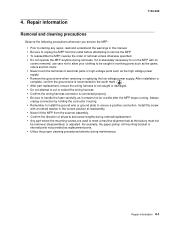
... understand the warnings in revolving parts such as it is connected properly. • Be sure to handle the fuser carefully, as the gears, rollers and fan motor. • Never touch the terminals of all parts and screw lengths during maintenance. Repair information 4-1 After installation is complete, confirm the ground wire is...
... understand the warnings in revolving parts such as it is connected properly. • Be sure to handle the fuser carefully, as the gears, rollers and fan motor. • Never touch the terminals of all parts and screw lengths during maintenance. Repair information 4-1 After installation is complete, confirm the ground wire is...

Service Manual
Page 183
Fuser fan assembly removal 1. A Repair information 4-43 Remove the left tray guide assembly out in front of the interlock assembly. See "Left rear cover removal" on page 4-...
Fuser fan assembly removal 1. A Repair information 4-43 Remove the left tray guide assembly out in front of the interlock assembly. See "Left rear cover removal" on page 4-...

Service Manual
Page 184
B 6. Lift and remove the fuser fan assembly. 4-44 Service Manual Disconnect the fuser fan cable from the connector (B) behind the interlock assembly. 7100-XXX 5. Remove the three screws (D) that secures the system board cage to the printer engine frame. 8. Remove the top screw (C) that secure the fuser fan assembly to the printer frame. D C 7.
B 6. Lift and remove the fuser fan assembly. 4-44 Service Manual Disconnect the fuser fan cable from the connector (B) behind the interlock assembly. 7100-XXX 5. Remove the three screws (D) that secures the system board cage to the printer engine frame. 8. Remove the top screw (C) that secure the fuser fan assembly to the printer frame. D C 7.

Service Manual
Page 188
Remove screw (A) from the interlock switches and remove the power supply fan. While holding the fan, disconnect the cables (B) from the power supply fan. A 4. B 4-48 Service Manual 7100-XXX Power supply fan removal 1. Disconnect the modem speaker cable from the system board, and carefully route the cable through the engine board cage. 3. Remove the top cover assembly. See "Top cover assembly removal" on page 4-10. 2.
Remove screw (A) from the interlock switches and remove the power supply fan. While holding the fan, disconnect the cables (B) from the power supply fan. A 4. B 4-48 Service Manual 7100-XXX Power supply fan removal 1. Disconnect the modem speaker cable from the system board, and carefully route the cable through the engine board cage. 3. Remove the top cover assembly. See "Top cover assembly removal" on page 4-10. 2.

Service Manual
Page 190
7100-XXX 7. Route all the cables through the RIP cage and around the fuser fan. 8. Remove the ribbon cable guide from the ribbon cable and flatbed unit. 9. Remove the four screws (C) that attach the flatbed to the scanner arms. C 4-50 Service Manual
7100-XXX 7. Route all the cables through the RIP cage and around the fuser fan. 8. Remove the ribbon cable guide from the ribbon cable and flatbed unit. 9. Remove the four screws (C) that attach the flatbed to the scanner arms. C 4-50 Service Manual

Service Manual
Page 200
... Stopper for exited papers. Standard paper tray that supplies AC power to the host by USB. Turns the printer on and off. Covers the fuser fan. Upper enclosure and also the paper exit tray.
... Stopper for exited papers. Standard paper tray that supplies AC power to the host by USB. Turns the printer on and off. Covers the fuser fan. Upper enclosure and also the paper exit tray.

Service Manual
Page 204
... laser beam scanning in optical unit Exhausts heat from power supply unit and interface controller. 7100-XXX Fan/motor and interlock switch locations Name Main motor Developer motors Scanner motor Power supply fan Exit fan Laser fan Front interlock switch Paper exit assembly interlock switch Top interlock switch Code MM DM SCM PSFAN EXFAN...
... laser beam scanning in optical unit Exhausts heat from power supply unit and interface controller. 7100-XXX Fan/motor and interlock switch locations Name Main motor Developer motors Scanner motor Power supply fan Exit fan Laser fan Front interlock switch Paper exit assembly interlock switch Top interlock switch Code MM DM SCM PSFAN EXFAN...

