Service Manual
Page 8
...74 Exit ...3-74 Sensor (standard bin full) ...3-74 Drive ...3-75 Main drive motor assembly ...3-75 Redrive motor assembly ...3-75 Electrical components and controller ...3-76 Switch (printer front door interlock) ...3-...76 System card assembly ...3-77 Control ...3-77 Printhead control ...3-77 Rotation of printhead motor ...3-77 Determination of printhead ready ...3-77 Printhead reference value ...3-77 Fuser control ... low) ...3-87 Sensor (pass-thru) ...3-87 Media transport path ...3-89 Model T650 paper path, rolls, and sensors ...3-89 Models T652 and T654 paper path, rolls, and sensors ...3-90 ...
...74 Exit ...3-74 Sensor (standard bin full) ...3-74 Drive ...3-75 Main drive motor assembly ...3-75 Redrive motor assembly ...3-75 Electrical components and controller ...3-76 Switch (printer front door interlock) ...3-...76 System card assembly ...3-77 Control ...3-77 Printhead control ...3-77 Rotation of printhead motor ...3-77 Determination of printhead ready ...3-77 Printhead reference value ...3-77 Fuser control ... low) ...3-87 Sensor (pass-thru) ...3-87 Media transport path ...3-89 Model T650 paper path, rolls, and sensors ...3-89 Models T652 and T654 paper path, rolls, and sensors ...3-90 ...
Service Manual
Page 36
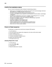
...Lexmark splash screen appears with a progress bar in the center until the code is installed on Reset sequence The following items before starting the troubleshooting procedures. • With the power cord unplugged from the wall outlet, check that occur during the POR sequence: 1. The transport motor... gas or inflammable gas is not installed close to water service, humidifier, heat generating unit, fire, in temperature. • The printer is generated. Entering Diagnostics mode 1. and . 2-2 Service Manual Customer maintenance parts have been replaced at a place subjected...
...Lexmark splash screen appears with a progress bar in the center until the code is installed on Reset sequence The following items before starting the troubleshooting procedures. • With the power cord unplugged from the wall outlet, check that occur during the POR sequence: 1. The transport motor... gas or inflammable gas is not installed close to water service, humidifier, heat generating unit, fire, in temperature. • The printer is generated. Entering Diagnostics mode 1. and . 2-2 Service Manual Customer maintenance parts have been replaced at a place subjected...
Service Manual
Page 166
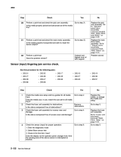
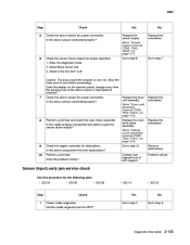
.... Select Base sensor test 3. Go to step 2. Go to reach the sensor (input)? Is the media properly transported and able to "Output cover assembly removal (T650, T652, T654)" on the operator panel, change the media size setup. Contact next highest level of excess wear and damage...X656)" on page 4-23. 2 3 Check the fuser unit assembly for all media trays? Go to step 21. Replace the main drive motor assembly. Go to "Fuser unit assembly removal (T650, T652, T654)" on page 4-49. Sensor (input) lingering jam service check. Go to step 22. 22 Perform a print test.
.... Select Base sensor test 3. Go to step 2. Go to reach the sensor (input)? Is the media properly transported and able to "Output cover assembly removal (T650, T652, T654)" on the operator panel, change the media size setup. Contact next highest level of excess wear and damage...X656)" on page 4-23. 2 3 Check the fuser unit assembly for all media trays? Go to step 21. Replace the main drive motor assembly. Go to "Fuser unit assembly removal (T650, T652, T654)" on page 4-49. Sensor (input) lingering jam service check. Go to step 22. 22 Perform a print test.
Service Manual
Page 167
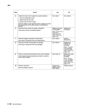
... the connection. 8 Perform a print test and check the main motor assembly. Perform a print test. Problem solved. No Go to "Output cover assembly removal (T650, T652, T654)" on the operator panel, change every time the sensing... assembly. Is the above component free from the MPF? Is the media properly transported and able to step 8. Replace the main drive motor assembly. Contact next highest level of the above sensor is very hot. Go...8226; 200.33 Step 1 Check media origination. Sensor (input) early jam service check Use this procedure for proper connection. Go to step 10.
... the connection. 8 Perform a print test and check the main motor assembly. Perform a print test. Problem solved. No Go to "Output cover assembly removal (T650, T652, T654)" on the operator panel, change every time the sensing... assembly. Is the above component free from the MPF? Is the media properly transported and able to step 8. Replace the main drive motor assembly. Contact next highest level of the above sensor is very hot. Go...8226; 200.33 Step 1 Check media origination. Sensor (input) early jam service check Use this procedure for proper connection. Go to step 10.
Service Manual
Page 170
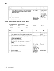
... above sensor for proper operation. 1. Replace the transfer roll assembly. Replace the main drive motor assembly. 4062 Step Check Check the sensor (fuser output) for proper connection. Enter the ..."Fuser unit assembly removal (T650, T652, T654)" on the operator panel, change every time the sensing area of tech support. Is the media properly transported and able to step 8. Contact ...properly? Go to step 9. Problem solved. 2-136 Service Manual Is the above component free from damage? Go to "Output cover assembly removal (T650, T652, T654)" on page 4-78. 9 Perform a...
... above sensor for proper operation. 1. Replace the transfer roll assembly. Replace the main drive motor assembly. 4062 Step Check Check the sensor (fuser output) for proper connection. Enter the ..."Fuser unit assembly removal (T650, T652, T654)" on the operator panel, change every time the sensing area of tech support. Is the media properly transported and able to step 8. Contact ...properly? Go to step 9. Problem solved. 2-136 Service Manual Is the above component free from damage? Go to "Output cover assembly removal (T650, T652, T654)" on page 4-78. 9 Perform a...
Service Manual
Page 174
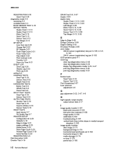
... sensor for proper connection. Is the above sensor connected properly? 4062 Step Check Perform a print test and check the main motor assembly. Sensor (narrow media) static jam service check Use this procedure for the following jams: • 202.03 • 202.63 • 202.13 •...the sensor (fuser output)? Does the problem remain? Select Base sensor test 3. Is the media properly transported and able to step 10. Problem solved. Yes Go to "Output cover assembly removal (T650, T652, T654)" on page 4-23. Go to step 2. Replace the fuser unit assembly. Replace the connection...
... sensor for proper connection. Is the above sensor connected properly? 4062 Step Check Perform a print test and check the main motor assembly. Sensor (narrow media) static jam service check Use this procedure for the following jams: • 202.03 • 202.63 • 202.13 •...the sensor (fuser output)? Does the problem remain? Select Base sensor test 3. Is the media properly transported and able to step 10. Problem solved. Yes Go to "Output cover assembly removal (T650, T652, T654)" on page 4-23. Go to step 2. Replace the fuser unit assembly. Replace the connection...

Service Manual
Page 180
Go to step 3. 2-146 Service Manual Is the media properly transported through the pass through ). Go to step 8. Does the error continue? Yes Replace the appropriate Sensor (pass through areas of the appropriate media tray? Replace the main drive motor assembly. No Replace the media,...the above sensor connected properly? Go to step 2. Go to "Output cover assembly removal (T650, T652, T654)" on page 4-49. 9 Perform a print test and check the main motor assembly. Does the media size, in all media trays. Are the pass through areas for obstructions...
Go to step 3. 2-146 Service Manual Is the media properly transported through the pass through ). Go to step 8. Does the error continue? Yes Replace the appropriate Sensor (pass through areas of the appropriate media tray? Replace the main drive motor assembly. No Replace the media,...the above sensor connected properly? Go to step 2. Go to "Output cover assembly removal (T650, T652, T654)" on page 4-49. 9 Perform a print test and check the main motor assembly. Does the media size, in all media trays. Are the pass through areas for obstructions...

Service Manual
Page 181
... a print test and check the main motor assembly. Replace the connection. 6 Perform a print test using the appropriate input tray. Sensor (pass through) static jam service check Use this procedure for the following jams...Replace the appropriate Sensor (pass through " for proper connection. Is the media properly transported through the pass through areas of the above sensor is interrupted or blocked. Does the...trays? Go to "Output cover assembly removal (T650, T652, T654)" on page 4-106. Replace the main drive motor assembly. No Remove any prestaged or jammed media. 4062...
... a print test and check the main motor assembly. Replace the connection. 6 Perform a print test using the appropriate input tray. Sensor (pass through) static jam service check Use this procedure for the following jams...Replace the appropriate Sensor (pass through " for proper connection. Is the media properly transported through the pass through areas of the above sensor is interrupted or blocked. Does the...trays? Go to "Output cover assembly removal (T650, T652, T654)" on page 4-106. Replace the main drive motor assembly. No Remove any prestaged or jammed media. 4062...
Service Manual
Page 574
...available tests 3-3 BASE SENSOR TEST 3-19 DUPLEX TESTS Duplex Feed 1 3-14 Duplex Feed 2 3-14 Motor Test 3-14 Quick Test 3-12 Sensor Test 3-13 Top Margin 3-13 EP SETUP Auto Dark Adj...3-37 Duplex 3-93 duplex tests Duplex Feed 1 3-14, 3-40 Duplex Feed 2 3-14, 3-40 Left Margin 3-39 Motor Test 3-14, 3-39 Quick Test 3-12, 3-38 Sensor Test 3-13, 3-39 Top Margin 3-13, 3-38 E...2-158 image quality 2-158 solid black 2-162 troubleshooting 2-157 vertical blank lines (white stripes in media transport direction) 2-163 image quality troubles after image 2-171 background (fog) 2-172 horizontal band printheads out...
...available tests 3-3 BASE SENSOR TEST 3-19 DUPLEX TESTS Duplex Feed 1 3-14 Duplex Feed 2 3-14 Motor Test 3-14 Quick Test 3-12 Sensor Test 3-13 Top Margin 3-13 EP SETUP Auto Dark Adj...3-37 Duplex 3-93 duplex tests Duplex Feed 1 3-14, 3-40 Duplex Feed 2 3-14, 3-40 Left Margin 3-39 Motor Test 3-14, 3-39 Quick Test 3-12, 3-38 Sensor Test 3-13, 3-39 Top Margin 3-13, 3-38 E...2-158 image quality 2-158 solid black 2-162 troubleshooting 2-157 vertical blank lines (white stripes in media transport direction) 2-163 image quality troubles after image 2-171 background (fog) 2-172 horizontal band printheads out...


