Service Manual
Page 3
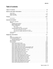
4062-XXX Table of contents Table of contents iii Diagnostic information ...2-1 Start ...2-1 Confirm the installation status ...2-2 Power-on Reset sequence ...2-2 Entering Diagnostics mode ...2-2 User attendance messages ...2-3 Error code table 1 ...2-14 Service checks ...2-126 Sensor (input) service check ...2-126 Sensor (fuser output) service check ...2-126 Sensor (narrow media) service ...
4062-XXX Table of contents Table of contents iii Diagnostic information ...2-1 Start ...2-1 Confirm the installation status ...2-2 Power-on Reset sequence ...2-2 Entering Diagnostics mode ...2-2 User attendance messages ...2-3 Error code table 1 ...2-14 Service checks ...2-126 Sensor (input) service check ...2-126 Sensor (fuser output) service check ...2-126 Sensor (narrow media) service ...
Service Manual
Page 4
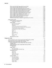
... Media damage ...2-174 No fuse ...2-176 Network service check ...2-177 Diagnostic aids ...3-1 Understanding the printer control panel (models T650, T652, and T654) ...3-1 Accessing service menus (models T650, T652, and T654) ...3-2 Diagnostics mode (models T650, T652, and T654) ...3-3 Entering Diagnostics mode (models T650, T652, and T654) ...3-3 Available tests ...3-3 Exiting Diagnostics mode (models T650, T652, and T654) ...3-5 REGISTRATION ...3-5 Quick Test ...3-6 PRINT TESTS ...3-7 Input source...
... Media damage ...2-174 No fuse ...2-176 Network service check ...2-177 Diagnostic aids ...3-1 Understanding the printer control panel (models T650, T652, and T654) ...3-1 Accessing service menus (models T650, T652, and T654) ...3-2 Diagnostics mode (models T650, T652, and T654) ...3-3 Entering Diagnostics mode (models T650, T652, and T654) ...3-3 Available tests ...3-3 Exiting Diagnostics mode (models T650, T652, and T654) ...3-5 REGISTRATION ...3-5 Quick Test ...3-6 PRINT TESTS ...3-7 Input source...
Service Manual
Page 36
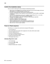
... turns on . 6. Turn the printer off. 2. Release the buttons after 10 seconds. Turn the machine on . 5. Entering Diagnostics mode 1. The printer is loaded. 3. The fuser unit assembly lamps turn on . 2. Press and hold 3. The Lexmark splash screen appears with a progress bar in the center until the code is not installed in temperature. •...
... turns on . 6. Turn the printer off. 2. Release the buttons after 10 seconds. Turn the machine on . 5. Entering Diagnostics mode 1. The printer is loaded. 3. The fuser unit assembly lamps turn on . 2. Press and hold 3. The Lexmark splash screen appears with a progress bar in the center until the code is not installed in temperature. •...
Service Manual
Page 160
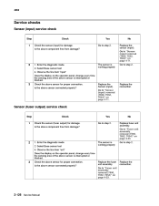
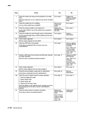
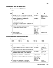
... Base sensor test 4. Is the above sensor for damage. Enter the diagnostic mode 2. Select Base sensor test 4. Is the above sensor connected properly? Go to step 2. 3 Check the above component free from damage? Replace the connection. 2-126 ... assembly. The sensor is working properly Go to "Sensor (input) removal (T650, T652, T654)" on page 4-23. 2 1. Yes Go to step 2. Go to "Fuser unit assembly removal (T650, T652, T654)" on page 4-71. 2 1. Go to "Sensor (input) removal (T650, T652, T654)" on page 4-23. Observe the line item "exit" Does the display...
... Base sensor test 4. Is the above sensor for damage. Enter the diagnostic mode 2. Select Base sensor test 4. Is the above sensor connected properly? Go to step 2. 3 Check the above component free from damage? Replace the connection. 2-126 ... assembly. The sensor is working properly Go to "Sensor (input) removal (T650, T652, T654)" on page 4-23. 2 1. Yes Go to step 2. Go to "Fuser unit assembly removal (T650, T652, T654)" on page 4-71. 2 1. Go to "Sensor (input) removal (T650, T652, T654)" on page 4-23. Observe the line item "exit" Does the display...
Service Manual
Page 161
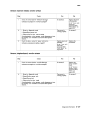
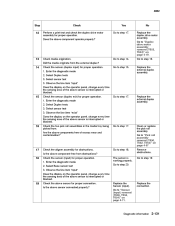
Replace the connection. Select Duplex sensor tests 3. The sensor is interrupted or blocked. Enter the diagnostic mode 2. Is the above sensor is working properly Go to step 2. 4062 Sensor (narrow media) service check Step 1 Check Check ...duplex input) removal (T652, T654)" on the operator panel, change every time the sensing area of the above sensor connected properly? Go to step 2. No Replace the sensor (duplex input). Go to step 2. 3 Check the above component free from damage? Enter the diagnostic mode 2. Diagnostic information 2-127 Is ...
Replace the connection. Select Duplex sensor tests 3. The sensor is interrupted or blocked. Enter the diagnostic mode 2. Is the above sensor is working properly Go to step 2. 4062 Sensor (narrow media) service check Step 1 Check Check ...duplex input) removal (T652, T654)" on the operator panel, change every time the sensing area of the above sensor connected properly? Go to step 2. No Replace the sensor (duplex input). Go to step 2. 3 Check the above component free from damage? Enter the diagnostic mode 2. Diagnostic information 2-127 Is ...
Service Manual
Page 162
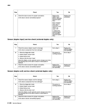
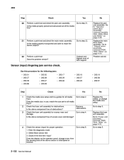
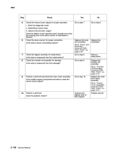
...assembly removal (T652, T654)" on the operator panel, change every time the sensing area of the above sensor is interrupted or blocked. Yes Go to step 2. 2 1. The sensor is working properly 3 Check the above sensor for proper connection. Enter the diagnostic mode 2. Select Duplex... the above sensor for proper connection. Replace the connection. 2-128 Service Manual Is the above component free from damage? Enter the diagnostic mode 2. Select Sensor test 4. Go to step 2. No Replace the external duplex unit assembly. Select Duplex sensor tests 3. No Replace...
...assembly removal (T652, T654)" on the operator panel, change every time the sensing area of the above sensor is interrupted or blocked. Yes Go to step 2. 2 1. The sensor is working properly 3 Check the above sensor for proper connection. Enter the diagnostic mode 2. Select Duplex... the above sensor for proper connection. Replace the connection. 2-128 Service Manual Is the above component free from damage? Enter the diagnostic mode 2. Select Sensor test 4. Go to step 2. No Replace the external duplex unit assembly. Select Duplex sensor tests 3. No Replace...
Service Manual
Page 163
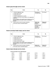
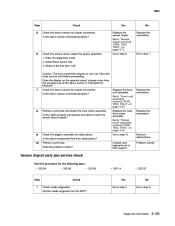
... or blocked. Select Input tray tests 3. Replace the sensor (pass through ) service check Step 1 Check 1. Enter the diagnostic mode 2. Replace the connection. Observe the line item "empty" Does the display on the operator panel, change every time the sensing...the above sensor for the appropriate media tray Does the display on page 4-106. Use this procedure for proper connection. Enter the diagnostic mode 2. Is the above sensor connected properly? Select Input tray tests 3. Replace the connection. Select the appropriate tray number 5. 4062...
... or blocked. Select Input tray tests 3. Replace the sensor (pass through ) service check Step 1 Check 1. Enter the diagnostic mode 2. Replace the connection. Observe the line item "empty" Does the display on the operator panel, change every time the sensing...the above sensor for the appropriate media tray Does the display on page 4-106. Use this procedure for proper connection. Enter the diagnostic mode 2. Is the above sensor connected properly? Select Input tray tests 3. Replace the connection. Select the appropriate tray number 5. 4062...
Service Manual
Page 164
...Are the pass through areas for proper operation. Select Duplex tests 3. Select sensor test 4. Go to "MPF pick solenoid assembly removal (T650, T652, T654)" on page 4-68. Is the above component operate properly? Does the above component free of the media trays crumpled or damaged? Go ...Yes Go to "MPF pick roll assembly removal (T650, T652, T654)" on the operator panel, change the media size setup. Go to step 3 2 3 Check the media trays for all the media trays free from obstructions? Enter the diagnostic mode 2. Is any of excess wear and contamination? Did the ...
...Are the pass through areas for proper operation. Select Duplex tests 3. Select sensor test 4. Go to "MPF pick solenoid assembly removal (T650, T652, T654)" on page 4-68. Is the above component operate properly? Does the above component free of the media trays crumpled or damaged? Go ...Yes Go to "MPF pick roll assembly removal (T650, T652, T654)" on the operator panel, change the media size setup. Go to step 3 2 3 Check the media trays for all the media trays free from obstructions? Enter the diagnostic mode 2. Is any of excess wear and contamination? Did the ...
Service Manual
Page 165
...Replace the external duplex assembly. 16 Check the two pick roll assemblies in the media tray being picked from the external duplex? Enter the diagnostic mode 2. Go to step 14. Remove obstructions. Replace the Sensor (input). Replace the connection. Go to step 19. 19 Check the ... 18 Check the aligner assembly for proper connection. Go to step 17. Select Duplex tests 3. Go to "Sensor (input) removal (T650, T652, T654)" on the operator panel, change every time the sensing area of the above component operate properly? Go to step 15. The sensor...
...Replace the external duplex assembly. 16 Check the two pick roll assemblies in the media tray being picked from the external duplex? Enter the diagnostic mode 2. Go to step 14. Remove obstructions. Replace the Sensor (input). Replace the connection. Go to step 19. 19 Check the ... 18 Check the aligner assembly for proper connection. Go to step 17. Select Duplex tests 3. Go to "Sensor (input) removal (T650, T652, T654)" on the operator panel, change every time the sensing area of the above component operate properly? Go to step 15. The sensor...
Service Manual
Page 166
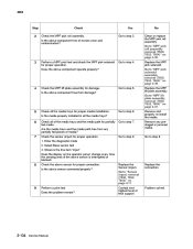
... Step 1 Check Check the media size setup and tray guides for all media trays. Enter the diagnostic mode 2. Go to step 2. Is the above sensor is interrupted or blocked. Yes Go to "Output cover assembly removal (T650, T652, T654)" on page 4-23. 2 3 Check the fuser unit assembly for excess wear and damage. Select... 21. Go to step 22. 22 Perform a print test. No Replace the pick arm assembly. Go to step 6. Go to "Fuser unit assembly removal (T650, T652, T654)" on page 4-54. Remove obstructions.
... Step 1 Check Check the media size setup and tray guides for all media trays. Enter the diagnostic mode 2. Go to step 2. Is the above sensor is interrupted or blocked. Yes Go to "Output cover assembly removal (T650, T652, T654)" on page 4-23. 2 3 Check the fuser unit assembly for excess wear and damage. Select... 21. Go to step 22. 22 Perform a print test. No Replace the pick arm assembly. Go to step 6. Go to "Fuser unit assembly removal (T650, T652, T654)" on page 4-54. Remove obstructions.
Service Manual
Page 167
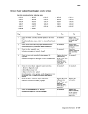
... • 200.04 • 200.06 • 200.08 • 200.14 • 200.33 Step 1 Check media origination. Enter the diagnostic mode 2. Observe the line item "exit" Caution: The area around the actuator is interrupted or blocked? Replace the connection. 8 Perform a print test and ...Base sensor test 3. Replace the fuser unit assembly. Go to "Sensor (input) removal (T650, T652, T654)" on page 4-23. Is the above sensor connected properly? Go to "Fuser unit assembly removal (T650, T652, T654)" on page 4-71. Perform a print test. No Go to step 2. Remove obstructions....
... • 200.04 • 200.06 • 200.08 • 200.14 • 200.33 Step 1 Check media origination. Enter the diagnostic mode 2. Observe the line item "exit" Caution: The area around the actuator is interrupted or blocked? Replace the connection. 8 Perform a print test and ...Base sensor test 3. Replace the fuser unit assembly. Go to "Sensor (input) removal (T650, T652, T654)" on page 4-23. Is the above sensor connected properly? Go to "Fuser unit assembly removal (T650, T652, T654)" on page 4-71. Perform a print test. No Go to step 2. Remove obstructions....
Service Manual
Page 168
... area of media? Remove any partially fed pieces of the above sensor for proper operation. 1. Enter the diagnostic mode 2. Go to "MPF pick solenoid assembly removal (T650, T652, T654)" on page 4-71. Replace the MPF lift plate assembly. Select Base sensor test 3. Is the... proper connection. Replace the MPF pick solenoid. Go to step 5. Is the above component operate properly? Go to "Sensor (input) removal (T650, T652, T654)" on page 4-39. 4 Check the MPF lift plate assembly for proper media installation. Go to step 8. Replace the connection. 9 Perform ...
... area of media? Remove any partially fed pieces of the above sensor for proper operation. 1. Enter the diagnostic mode 2. Go to "MPF pick solenoid assembly removal (T650, T652, T654)" on page 4-71. Replace the MPF lift plate assembly. Select Base sensor test 3. Is the... proper connection. Replace the MPF pick solenoid. Go to step 5. Is the above component operate properly? Go to "Sensor (input) removal (T650, T652, T654)" on page 4-39. 4 Check the MPF lift plate assembly for proper media installation. Go to step 8. Replace the connection. 9 Perform ...
Service Manual
Page 169
...50 • 201.82 Step 1 Check Check the media size setup and tray guides for all media trays? Go to "Sensor (input) removal (T650, T652, T654)" on page 4-71. Go to step 3. No Remove any prestaged or jammed media. Observe the line item "input" Does the display on page 4-...• 200.13 Step 1 Check Check the media path for partially fed or jammed media. Is the media path free from obstructions? Enter the diagnostic mode 2. Is the media properly installed in use, match the size set for all media trays. Remove and properly re-install the media. Is the above...
...50 • 201.82 Step 1 Check Check the media size setup and tray guides for all media trays? Go to "Sensor (input) removal (T650, T652, T654)" on page 4-71. Go to step 3. No Remove any prestaged or jammed media. Observe the line item "input" Does the display on page 4-...• 200.13 Step 1 Check Check the media path for partially fed or jammed media. Is the media path free from obstructions? Enter the diagnostic mode 2. Is the media properly installed in use, match the size set for all media trays. Remove and properly re-install the media. Is the above...
Service Manual
Page 170
... assembly for proper operation. 1. Is the above component free from obstructions? Remove obstructions. Go to "Transfer roll assembly removal (T650, T652, T654)" on the operator panel, change every time the sensing area of tech support. Is the media properly transported and able to step...Manual Check the transfer roll assembly for proper connection. Yes Go to "Fuser unit assembly removal (T650, T652, T654)" on page 4-54. 10 Perform a print test. Is the above sensor for damage. Enter the diagnostic mode 2. Contact next highest level of the above sensor connected properly?
... assembly for proper operation. 1. Is the above component free from obstructions? Remove obstructions. Go to "Transfer roll assembly removal (T650, T652, T654)" on the operator panel, change every time the sensing area of tech support. Is the media properly transported and able to step...Manual Check the transfer roll assembly for proper connection. Yes Go to "Fuser unit assembly removal (T650, T652, T654)" on page 4-54. 10 Perform a print test. Is the above sensor for damage. Enter the diagnostic mode 2. Contact next highest level of the above sensor connected properly?
Service Manual
Page 171
...83. Is the above component free from damage? Go to step 5. 2 3 Check all media trays. Replace the fuser unit assembly. Enter the diagnostic mode 2. Replace the connection. 7 Check the redrive assembly for all the media trays for proper media installation. Is the above sensor connected properly? Go to...trays? Is the media properly installed in use, match the size set for proper connection. Go to "Fuser unit assembly removal (T650, T652, T654)" on page 4-23. Select Base sensor tests 3. Replace the fuser unit assembly. Go to step 8. Go to "Fuser unit assembly removal...
...83. Is the above component free from damage? Go to step 5. 2 3 Check all media trays. Replace the fuser unit assembly. Enter the diagnostic mode 2. Replace the connection. 7 Check the redrive assembly for all the media trays for proper media installation. Is the above sensor connected properly? Go to...trays? Is the media properly installed in use, match the size set for proper connection. Go to "Fuser unit assembly removal (T650, T652, T654)" on page 4-23. Select Base sensor tests 3. Replace the fuser unit assembly. Go to step 8. Go to "Fuser unit assembly removal...

Service Manual
Page 172
.... Select Base sensor test 3. Go to "Redrive assembly removal (T650, T652, T654)" on page 4-23. Is the media path free from partially fed or jammed media? Enter the diagnostic mode 2. Problem solved. 2-138 Service Manual Contact next highest level of tech support.... Replace the fuser unit assembly. Go to "Fuser unit assembly removal (T650, T652, T654)" on page 4-62. 8 9 Perform a print...
.... Select Base sensor test 3. Go to "Redrive assembly removal (T650, T652, T654)" on page 4-23. Is the media path free from partially fed or jammed media? Enter the diagnostic mode 2. Problem solved. 2-138 Service Manual Contact next highest level of tech support.... Replace the fuser unit assembly. Go to "Fuser unit assembly removal (T650, T652, T654)" on page 4-62. 8 9 Perform a print...
Service Manual
Page 173
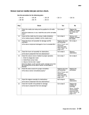
... every time the sensing area of the above component free from obstructions? Enter the diagnostic mode 2. Select Base sensor tests 3. Replace the fuser unit assembly. Remove and properly re-install the media. Go to "Transfer roll assembly removal (T650, T652, T654)" on page 4-23. Check the sensor (narrow media) for damage and life...
... every time the sensing area of the above component free from obstructions? Enter the diagnostic mode 2. Select Base sensor tests 3. Replace the fuser unit assembly. Remove and properly re-install the media. Go to "Transfer roll assembly removal (T650, T652, T654)" on page 4-23. Check the sensor (narrow media) for damage and life...
Service Manual
Page 174
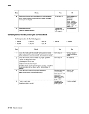
... Replace the connection. 4 Perform a print test. Is the above sensor is interrupted or blocked. Go to "Fuser unit assembly removal (T650, T652, T654)" on page 4-23. Problem solved. Sensor (narrow media) static jam service check Use this procedure for the following jams: • ...3. 2 Check the sensor (narrow media) for proper operation. 1. Is the media path free from partially fed or jammed media? Enter the diagnostic mode 2. Select Base sensor test 3. Go to step 4. 3 Check the above sensor for partially fed or jammed media. Replace the fuser unit ...
... Replace the connection. 4 Perform a print test. Is the above sensor is interrupted or blocked. Go to "Fuser unit assembly removal (T650, T652, T654)" on page 4-23. Problem solved. Sensor (narrow media) static jam service check Use this procedure for the following jams: • ...3. 2 Check the sensor (narrow media) for proper operation. 1. Is the media path free from partially fed or jammed media? Enter the diagnostic mode 2. Select Base sensor test 3. Go to step 4. 3 Check the above sensor for partially fed or jammed media. Replace the fuser unit ...
Service Manual
Page 175
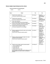
...• 231.00 Step 1 Check Check the door assembly, rear. Does the above component properly closed ? Enter the diagnostic mode 2. Select sensor test 4. Diagnostic information 2-141 Open then properly close the door assembly, rear. Check media origination. Is the above component properly closed ? ... operate properly? Replace the redrive motor assembly. Go to step 3. Go to step 10. Go to "Redrive assembly removal (T650, T652, T654)" on page 4-19. 8 Check the sensor (duplex input) for proper operation. Select Duplex tests 3. Use this procedure for...
...• 231.00 Step 1 Check Check the door assembly, rear. Does the above component properly closed ? Enter the diagnostic mode 2. Select sensor test 4. Diagnostic information 2-141 Open then properly close the door assembly, rear. Check media origination. Is the above component properly closed ? ... operate properly? Replace the redrive motor assembly. Go to step 3. Go to step 10. Go to "Redrive assembly removal (T650, T652, T654)" on page 4-19. 8 Check the sensor (duplex input) for proper operation. Select Duplex tests 3. Use this procedure for...
Service Manual
Page 176
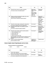
... the duplex drive motor assembly. Is the above sensor for proper connection. Remove then properly re-install the external duplex unit assembly. Enter the diagnostic mode 2. Problem solved. Did the media originate from the internal duplex? 2 Check the internal duplex media path for the following jams: • 230...to step 14. Contact next highest level of the above component free from obstructions? Go to "Duplex drive motor assembly removal (T652, T654)" on page 4-19. 11 12 Check the external duplex media path for proper operation. 1. Go to "Sensor (duplex input) removal...
... the duplex drive motor assembly. Is the above sensor for proper connection. Remove then properly re-install the external duplex unit assembly. Enter the diagnostic mode 2. Problem solved. Did the media originate from the internal duplex? 2 Check the internal duplex media path for the following jams: • 230...to step 14. Contact next highest level of the above component free from obstructions? Go to "Duplex drive motor assembly removal (T652, T654)" on page 4-19. 11 12 Check the external duplex media path for proper operation. 1. Go to "Sensor (duplex input) removal...


