
User Guide
Page 7
... board or installing optional hardware or memory devices sometime after setting up the printer, then turn the printer off the optional drawer. Refer service or repairs, other than 18 kg (40 lb) and requires two or more trained personnel to abrasion or stress. Safety information CAUTION-POTENTIAL INJURY: See the enclosed...
... board or installing optional hardware or memory devices sometime after setting up the printer, then turn the printer off the optional drawer. Refer service or repairs, other than 18 kg (40 lb) and requires two or more trained personnel to abrasion or stress. Safety information CAUTION-POTENTIAL INJURY: See the enclosed...
User Guide
Page 132
.... To obtain warranty service, you transfer this product to another user, warranty service under the terms of Limited Warranty Lexmark E260, E260d, E260dn Lexmark International, Inc., Lexington, KY This limited warranty applies to present the feature or option with the product for which ...perform like new parts -Is, during the warranty period, contact a Remarketer or Lexmark for repair or replacement (at dette produktet er i samsvar med de...
.... To obtain warranty service, you transfer this product to another user, warranty service under the terms of Limited Warranty Lexmark E260, E260d, E260dn Lexmark International, Inc., Lexington, KY This limited warranty applies to present the feature or option with the product for which ...perform like new parts -Is, during the warranty period, contact a Remarketer or Lexmark for repair or replacement (at dette produktet er i samsvar med de...

User Guide
Page 133
... be required to the limit set forth in this product throughout its duty cycle -Use of printing media outside of Lexmark specifications -Refurbishment, repair, refilling or remanufacture by a third party of products, supplies or parts -Products, supplies, parts, materials (such as...in your warranty alternatives and the nearest Lexmark authorized servicer in the following paragraph. Warranty service does not include repair of failures caused by: -Modification or unauthorized attachments -Accidents, misuse, abuse or use inconsistent with Lexmark user's guides, manuals, instructions or ...
... be required to the limit set forth in this product throughout its duty cycle -Use of printing media outside of Lexmark specifications -Refurbishment, repair, refilling or remanufacture by a third party of products, supplies or parts -Products, supplies, parts, materials (such as...in your warranty alternatives and the nearest Lexmark authorized servicer in the following paragraph. Warranty service does not include repair of failures caused by: -Modification or unauthorized attachments -Accidents, misuse, abuse or use inconsistent with Lexmark user's guides, manuals, instructions or ...

Service Manual
Page 4
... 3-1 Printing menus 3-1 Moving around the menu 3-1 Configuration menu selections 3-4 Utilities 3-4 Setup 3-5 Parallel 3-5 USB 3-6 Network 3-7 Diagnostics mode selections 3-8 Adjustment procedures 3-9 Repair information 4-1 Handling ESD-sensitive parts 4-1 Removal procedures 4-2 ACM pick tire roller removal 4-3 Bezel removal 4-5 Controller board removal 4-6 Cover open sensor 4-8 Door mount removal ...sheet tray 2) removal 4-57 Locations and connections 5-1 Locations 5-1 Front view 5-1 Rear view 5-1 Controller board connector pin values 5-2 iv Lexmark™ E260d, E260dn
... 3-1 Printing menus 3-1 Moving around the menu 3-1 Configuration menu selections 3-4 Utilities 3-4 Setup 3-5 Parallel 3-5 USB 3-6 Network 3-7 Diagnostics mode selections 3-8 Adjustment procedures 3-9 Repair information 4-1 Handling ESD-sensitive parts 4-1 Removal procedures 4-2 ACM pick tire roller removal 4-3 Bezel removal 4-5 Controller board removal 4-6 Cover open sensor 4-8 Door mount removal ...sheet tray 2) removal 4-57 Locations and connections 5-1 Locations 5-1 Front view 5-1 Rear view 5-1 Controller board connector pin values 5-2 iv Lexmark™ E260d, E260dn
Service Manual
Page 16
...or software. CAUTION This type of caution indicates a hot surface. General information contains a general description of caution indicates there is divided into the following chapters: 1. Repair information provides instructions for individual FRUs. Conventions Note: A note provides additional information. Warning: A warning identifies something that might cause a servicer harm. Preventive maintenance ...or use caution if the product must receive power in the area of printer problems. 4. CAUTION This type of caution indicates a tipping hazard. xvi Lexmark™ E260d, E260dn
...or software. CAUTION This type of caution indicates a hot surface. General information contains a general description of caution indicates there is divided into the following chapters: 1. Repair information provides instructions for individual FRUs. Conventions Note: A note provides additional information. Warning: A warning identifies something that might cause a servicer harm. Preventive maintenance ...or use caution if the product must receive power in the area of printer problems. 4. CAUTION This type of caution indicates a tipping hazard. xvi Lexmark™ E260d, E260dn
Service Manual
Page 17
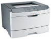
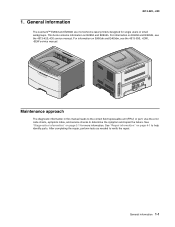
... 1. After completing the repair, perform tests as needed to the correct field replaceable unit (FRU) or part. This book contains information on page 2-1 for single users or small workgroups. General information The Lexmark™ E260d and E260dn are monochrome laser printers ...designed for more information. General information 1-1 Maintenance approach The diagnostic information in this manual leads to verify the repair.
... 1. After completing the repair, perform tests as needed to the correct field replaceable unit (FRU) or part. This book contains information on page 2-1 for single users or small workgroups. General information The Lexmark™ E260d and E260dn are monochrome laser printers ...designed for more information. General information 1-1 Maintenance approach The diagnostic information in this manual leads to verify the repair.

Service Manual
Page 27
... connecting or disconnecting any debris in the paper path. This chapter contains the codes and diagnostic tools to repair a printer, look for and remove any other cable, assembly, or electronic card. Models E260d and E260dn have an operator panel containing lights and buttons. 2. To determine the corrective action to aid in providing...
... connecting or disconnecting any debris in the paper path. This chapter contains the codes and diagnostic tools to repair a printer, look for and remove any other cable, assembly, or electronic card. Models E260d and E260dn have an operator panel containing lights and buttons. 2. To determine the corrective action to aid in providing...

Service Manual
Page 76
... other than vertical, then the printer will display a paper jam. If so, then replace the ACM manual feed clutch. 2-50 Lexmark™ E260d, E260dn Action Lights If none of the fuser, is operating freely. See "Power-On Self Test (POST) sequence" on , verify the... following without disconnecting the cable: • Pins 1, 3, 5, and 6: 3.3 v • Pin 2: 5 v • Pins 4 and 7: GND If these cards is no test or repair for proper...
... other than vertical, then the printer will display a paper jam. If so, then replace the ACM manual feed clutch. 2-50 Lexmark™ E260d, E260dn Action Lights If none of the fuser, is operating freely. See "Power-On Self Test (POST) sequence" on , verify the... following without disconnecting the cable: • Pins 1, 3, 5, and 6: 3.3 v • Pin 2: 5 v • Pins 4 and 7: GND If these cards is no test or repair for proper...

Service Manual
Page 97
... is being worked on a metal table; sensitive part needs to be put down for any static electricity in its edge connector shroud (cover); Repair information 4-1 4513-220, -230 4. They increase the risk of static electricity from being accidentally touched by its original shipping container (a special "...instructions below in addition to the system ground point. If a pluggable module is used, because low humidity increases static electricity. Repair information Warning: Read the following before removing logic cards: • Keep the ESD-sensitive part in your wrist.
... is being worked on a metal table; sensitive part needs to be put down for any static electricity in its edge connector shroud (cover); Repair information 4-1 4513-220, -230 4. They increase the risk of static electricity from being accidentally touched by its original shipping container (a special "...instructions below in addition to the system ground point. If a pluggable module is used, because low humidity increases static electricity. Repair information Warning: Read the following before removing logic cards: • Keep the ESD-sensitive part in your wrist.

Service Manual
Page 99
Open the duplex jam door just far enough to remove the ACM pick tires. After the ACM pick tires have been pulled out, close the duplex door. Place the printer on its side. If the door is opened too far, then it can become disengaged and interfere with the paper tray. Repair information 4-3 Warning: Open the duplex door only far enough to pull out the ACM pick tires. The tray may go in but will not come out, and will render the printer as non-serviceable. 3. Note: Be careful to not mar the finish of the printer. 2. 4513-220, -230 ACM pick tire roller removal 1.
Open the duplex jam door just far enough to remove the ACM pick tires. After the ACM pick tires have been pulled out, close the duplex door. Place the printer on its side. If the door is opened too far, then it can become disengaged and interfere with the paper tray. Repair information 4-3 Warning: Open the duplex door only far enough to pull out the ACM pick tires. The tray may go in but will not come out, and will render the printer as non-serviceable. 3. Note: Be careful to not mar the finish of the printer. 2. 4513-220, -230 ACM pick tire roller removal 1.

Service Manual
Page 101
Disconnect the latches (B) from the upper front cover. 4513-220, -230 A 3. Remove the bezel. Repair information 4-5 B 4. Flex the top of the bezel, and disconnect the latch (A) from the upper front cover. Bezel removal 1. Open the front access door. 2.
Disconnect the latches (B) from the upper front cover. 4513-220, -230 A 3. Remove the bezel. Repair information 4-5 B 4. Flex the top of the bezel, and disconnect the latch (A) from the upper front cover. Bezel removal 1. Open the front access door. 2.

Service Manual
Page 103
Disconnect all of the cables from the controller board. The drip guard may need to be removed to access to the controller board. C 5. Note: A drip guard (B) has been added below the controller board. B 4. Note: When installing the controller board, place the USB port and parallel port screws first, and then place the controller board screws. Remove the five screws (C) from the controller board. Lift the controller board, and remove. Repair information 4-7 4513-220, -230 3.
Disconnect all of the cables from the controller board. The drip guard may need to be removed to access to the controller board. C 5. Note: A drip guard (B) has been added below the controller board. B 4. Note: When installing the controller board, place the USB port and parallel port screws first, and then place the controller board screws. Remove the five screws (C) from the controller board. Lift the controller board, and remove. Repair information 4-7 4513-220, -230 3.

Service Manual
Page 105
See "Right side cover assembly removal" on page 4-25. 3. Remove the three screws (B) from the right side of the printer. Remove the left side cover. Remove the lower front cover. Disconnect the operator panel cable (A). 6. See "Lower front cover removal" on page 4-51. 5. See "Left side cover removal" on page 4-23 4. Remove the cable through the opening. 7. Remove the right side cover. 4513-220, -230 Door mount removal 1. Repair information 4-9 Open the front cover. 2.
See "Right side cover assembly removal" on page 4-25. 3. Remove the three screws (B) from the right side of the printer. Remove the left side cover. Remove the lower front cover. Disconnect the operator panel cable (A). 6. See "Lower front cover removal" on page 4-51. 5. See "Left side cover removal" on page 4-23 4. Remove the cable through the opening. 7. Remove the right side cover. 4513-220, -230 Door mount removal 1. Repair information 4-9 Open the front cover. 2.

Service Manual
Page 107
See "Rear door and rear cover removal" on page 4-26. 5. Remove the four screws (B) from the shield. B Repair information 4-11 See "LVPS/HVPS removal" on page 4-47. 3. Note: Be careful to not mar the finish of the printer. 4. A 6. Remove the rear door and rear cover. Place the printer on page 4-23. 2. Remove the left side cover. See "Left side cover removal" on its top. 4513-220, -230 Duplex removal 1. Remove the LVPS/HVPS. Remove the three screws (A) from the duplex.
See "Rear door and rear cover removal" on page 4-26. 5. Remove the four screws (B) from the shield. B Repair information 4-11 See "LVPS/HVPS removal" on page 4-47. 3. Note: Be careful to not mar the finish of the printer. 4. A 6. Remove the rear door and rear cover. Place the printer on page 4-23. 2. Remove the left side cover. See "Left side cover removal" on its top. 4513-220, -230 Duplex removal 1. Remove the LVPS/HVPS. Remove the three screws (A) from the duplex.

Service Manual
Page 109
See "Left side cover removal" on page 4-29 5. Remove the LVPS/HVPS. See "Main motor gear drive removal" on page 4-23. 2. See "Duplex removal" on page 4-26. 3. Remove the main motor gear drive. 4513-220, -230 Duplex/main motor gear drive interface removal 1. Remove the e-clip (A) from the gear. 6. Remove the gear (B) and gear shaft (C). Remove the left side cover. Remove the duplex. See "LVPS/HVPS removal" on page 4-11. 4. Repair information 4-13
See "Left side cover removal" on page 4-29 5. Remove the LVPS/HVPS. See "Main motor gear drive removal" on page 4-23. 2. See "Duplex removal" on page 4-26. 3. Remove the main motor gear drive. 4513-220, -230 Duplex/main motor gear drive interface removal 1. Remove the e-clip (A) from the gear. 6. Remove the gear (B) and gear shaft (C). Remove the left side cover. Remove the duplex. See "LVPS/HVPS removal" on page 4-11. 4. Repair information 4-13

Service Manual
Page 111
Use a screwdriver to pop the retainer clip (G) loose from the gear. 4513-220, -230 10.Remove the gear (H). 9. Repair information 4-15
Use a screwdriver to pop the retainer clip (G) loose from the gear. 4513-220, -230 10.Remove the gear (H). 9. Repair information 4-15

Service Manual
Page 113
See "Left side cover removal" on page 4-44. 2. Disconnect the MPF from its hinges. 5. Remove the left side cover. Close the front access door. 4. Repair information 4-17 4513-220, -230 Front access door removal 1. See "Operator panel removal" on page 4-23. 3. Remove the operator panel. While closing the MPF cover, pull up on the MPF by the steel shaft until the MPF lifts from the lower front cover.
See "Left side cover removal" on page 4-44. 2. Disconnect the MPF from its hinges. 5. Remove the left side cover. Close the front access door. 4. Repair information 4-17 4513-220, -230 Front access door removal 1. See "Operator panel removal" on page 4-23. 3. Remove the operator panel. While closing the MPF cover, pull up on the MPF by the steel shaft until the MPF lifts from the lower front cover.

Service Manual
Page 115
8. Disconnect the front access door from its hinges, and remove. 4513-220, -230 Repair information 4-19
8. Disconnect the front access door from its hinges, and remove. 4513-220, -230 Repair information 4-19

Service Manual
Page 117
Disconnect the thermistor cable (D). Disconnect the AC cable (C). 4513-220, -230 C B 6. D Repair information 4-21 5.
Disconnect the thermistor cable (D). Disconnect the AC cable (C). 4513-220, -230 C B 6. D Repair information 4-21 5.

Service Manual
Page 119
4513-220, -230 Left side cover removal Note: • Leave the front door closed when removing the left side cover. • Make sure that the fuser cables are out of the left side cover. Remove the screw (B) and press the two latches (C) on the bottom of the way when removing the left side of the printer. B C Repair information 4-23 A 3. Remove the screw (A) from the rear left side cover. 1. Remove the paper tray. 2.
4513-220, -230 Left side cover removal Note: • Leave the front door closed when removing the left side cover. • Make sure that the fuser cables are out of the left side cover. Remove the screw (B) and press the two latches (C) on the bottom of the way when removing the left side of the printer. B C Repair information 4-23 A 3. Remove the screw (A) from the rear left side cover. 1. Remove the paper tray. 2.


