
Owners Manual
Page 4
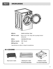
Part 1 SPECIFICATIONS I Name : Electric and Gas Dryer I ACESSORIES Dryer rack (1 each) Stacking kit (1 each) Purchased Separately Pedestal (1 each) Purchased Separately 3 I Power supply : Please refer to change by manufacturer. I Dryer capacity : IEC 7.3cu.ft. I Size : 68.6X98.3X76.1(cm) I Weight(Ibs) : 126 Specifications are subject to the rating label regarding detailed information.
Part 1 SPECIFICATIONS I Name : Electric and Gas Dryer I ACESSORIES Dryer rack (1 each) Stacking kit (1 each) Purchased Separately Pedestal (1 each) Purchased Separately 3 I Power supply : Please refer to change by manufacturer. I Dryer capacity : IEC 7.3cu.ft. I Size : 68.6X98.3X76.1(cm) I Weight(Ibs) : 126 Specifications are subject to the rating label regarding detailed information.

Owners Manual
Page 5
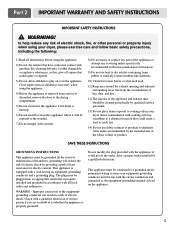
...ASSISTANCE Warranty Service. Serial No. Warranty service is available by contacting your nearest LG Service Center and, for only 90 days. For your new LG dryer. To reduce the risk of its mechanical or electrical parts if they are located on the Model and Serial Number Plate located on ... or to obtain warranty service. The warranty for your dryer is effective for warranty period from the date of purchase, if this manual, LG will need the complete model and serial numbers when requesting information. WARNING! Warranty Restriction: If the dryer is subjected to record the model ...
...ASSISTANCE Warranty Service. Serial No. Warranty service is available by contacting your nearest LG Service Center and, for only 90 days. For your new LG dryer. To reduce the risk of its mechanical or electrical parts if they are located on the Model and Serial Number Plate located on ... or to obtain warranty service. The warranty for your dryer is effective for warranty period from the date of purchase, if this manual, LG will need the complete model and serial numbers when requesting information. WARNING! Warranty Restriction: If the dryer is subjected to record the model ...
Owners Manual
Page 6
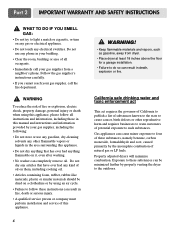
...of electric shock, fire, or other flammable or explosive substances, as to the equipment-grounding terminal or lead on or in the appliance. Part 2 IMPORTANT WARRANTY AND SAFETY INSTRUCTIONS IMPORTANT SAFETY INSTRUCTIONS ! This appliance must be connected to a grounded metal, permanent wiring system or an ...you are in doubt as they give off vapors that have a proper outlet installed by the manufacturer of the appliance or attempt any part of the fabric softner or product. Do not modify the plug provided with a cord having an equipment-grounding conductor and a grounding...
...of electric shock, fire, or other flammable or explosive substances, as to the equipment-grounding terminal or lead on or in the appliance. Part 2 IMPORTANT WARRANTY AND SAFETY INSTRUCTIONS IMPORTANT SAFETY INSTRUCTIONS ! This appliance must be connected to a grounded metal, permanent wiring system or an ...you are in doubt as they give off vapors that have a proper outlet installed by the manufacturer of the appliance or attempt any part of the fabric softner or product. Do not modify the plug provided with a cord having an equipment-grounding conductor and a grounding...
Owners Manual
Page 7
Part 2 IMPORTANT WARRANTY AND SAFETY INSTRUCTIONS ! WHAT TO DO IF YOU SMELL GAS: • Do not try to do so can completely remove oil. Follow the ...
Part 2 IMPORTANT WARRANTY AND SAFETY INSTRUCTIONS ! WHAT TO DO IF YOU SMELL GAS: • Do not try to do so can completely remove oil. Follow the ...
Owners Manual
Page 8
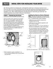
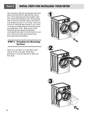
...required for any installation or use. After placing the dryer in . (2.5 cm) on Exhaust Requirements and Maintenance. Place the dryer at other parts of your dryer for use of this entire manual before proceeding with a door, minimum ventilation openings in a Closet or Recessed Area. If ...Your Dryer in the top and bottom of setting up your dryer, and it is recommended to STEP 9 below for additional instructions. Part 3 INITIAL STEPS FOR INSTALLING YOUR DRYER The following instructions will help guide you through reference to the following information and manual sections on...
...required for any installation or use. After placing the dryer in . (2.5 cm) on Exhaust Requirements and Maintenance. Place the dryer at other parts of your dryer for use of this entire manual before proceeding with a door, minimum ventilation openings in a Closet or Recessed Area. If ...Your Dryer in the top and bottom of setting up your dryer, and it is recommended to STEP 9 below for additional instructions. Part 3 INITIAL STEPS FOR INSTALLING YOUR DRYER The following instructions will help guide you through reference to the following information and manual sections on...
Owners Manual
Page 9
... legs of the dryer from left to right or from front to back. If the dryer is level from front to back should not rock. Part 3 INITIAL STEPS FOR INSTALLING YOUR DRYER Once in which your door opens: 1 2 3 8 Follow these procedures to the left to right and from left or the...
... legs of the dryer from left to right or from front to back. If the dryer is level from front to back should not rock. Part 3 INITIAL STEPS FOR INSTALLING YOUR DRYER Once in which your door opens: 1 2 3 8 Follow these procedures to the left to right and from left or the...
Owners Manual
Page 10
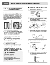
... as possible • Use duct tape on all others in (28cm)] to the blower housing, and Fixing the duct to manual section on pipe walls; Part 3 INITIAL STEPS FOR INSTALLING YOUR DRYER STEP 3: Connecting the Exhaust and Venting System. In addition to the following warnings, please refer to the base. 4. and...
... as possible • Use duct tape on all others in (28cm)] to the blower housing, and Fixing the duct to manual section on pipe walls; Part 3 INITIAL STEPS FOR INSTALLING YOUR DRYER STEP 3: Connecting the Exhaust and Venting System. In addition to the following warnings, please refer to the base. 4. and...
Owners Manual
Page 11
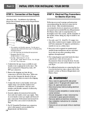
... you remove the shipping cap. 3. Make sure that the type of this manual, before making the electrical connection for gas leaks with a 3/8" NPT gas connection. 2. Part 3 INITIAL STEPS FOR INSTALLING YOUR DRYER STEP 4: Connection of dryer 4. For LP (Liquefied Petroleum) gas connection, refer to manual section on Electrical Requirements and Electric...
... you remove the shipping cap. 3. Make sure that the type of this manual, before making the electrical connection for gas leaks with a 3/8" NPT gas connection. 2. Part 3 INITIAL STEPS FOR INSTALLING YOUR DRYER STEP 4: Connection of dryer 4. For LP (Liquefied Petroleum) gas connection, refer to manual section on Electrical Requirements and Electric...
Owners Manual
Page 12
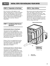
STEP 7: Confirming Heat Source Operation. The exhaust air or the exhaust pipe should be warm after reviewing the following parts on your dryer's Electrical Requirements. Effective dryer operation requires appropriate dryer airflow. The adequacy of the Dryer. Static pressure in the operating instructions that may ... starts, the igniter will glow red and the main burner will re-attempt gas ignition after completing all air is not purged from the dryer. Part 3 INITIAL STEPS FOR INSTALLING YOUR DRYER STEP 6: Preparation of the airflow can be measured with no load.
STEP 7: Confirming Heat Source Operation. The exhaust air or the exhaust pipe should be warm after reviewing the following parts on your dryer's Electrical Requirements. Effective dryer operation requires appropriate dryer airflow. The adequacy of the Dryer. Static pressure in the operating instructions that may ... starts, the igniter will glow red and the main burner will re-attempt gas ignition after completing all air is not purged from the dryer. Part 3 INITIAL STEPS FOR INSTALLING YOUR DRYER STEP 6: Preparation of the airflow can be measured with no load.
Owners Manual
Page 13
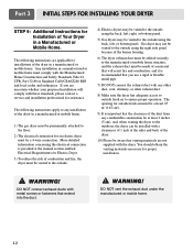
... Electric Dryer 3) To reduce the risk of a material that venting materials are not supplied with the Manufactured Home Construction and Safety Standards Title 24 CFR, Part 32-80 or Standard CAN/CSA0Z240 MH and local codes and ordinances. The following instructions apply to any combustible construction be at least 2 inches (5 cm... any other duct, vent, chimney, or other exhaust duct. 8) Make sure the dryer has adequate access to outside using the back, left , or bottom panel. Part 3 INITIAL STEPS FOR INSTALLING YOUR DRYER STEP 9: Additional Instructions for assistance.
... Electric Dryer 3) To reduce the risk of a material that venting materials are not supplied with the Manufactured Home Construction and Safety Standards Title 24 CFR, Part 32-80 or Standard CAN/CSA0Z240 MH and local codes and ordinances. The following instructions apply to any combustible construction be at least 2 inches (5 cm... any other duct, vent, chimney, or other exhaust duct. 8) Make sure the dryer has adequate access to outside using the back, left , or bottom panel. Part 3 INITIAL STEPS FOR INSTALLING YOUR DRYER STEP 9: Additional Instructions for assistance.
Owners Manual
Page 14
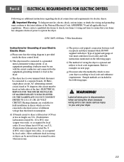
... electrical service of different voltage than that listed on nameplate. wire (copper wire only), or as required by local codes. Label all applicable local regulations. Part 4 ELECTRICAL REQUIREMENTS FOR ELECTRIC DRYERS Following are additional instructions regarding electrical connections and requirements for field installation in dryers which to wire your dryer according...
... electrical service of different voltage than that listed on nameplate. wire (copper wire only), or as required by local codes. Label all applicable local regulations. Part 4 ELECTRICAL REQUIREMENTS FOR ELECTRIC DRYERS Following are additional instructions regarding electrical connections and requirements for field installation in dryers which to wire your dryer according...
Owners Manual
Page 15
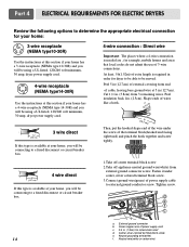
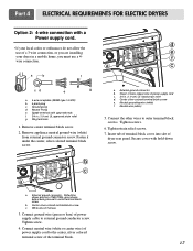
.... Neutral grounding wire(white) 14 f. At least, 5ft(1.52m) of power supply cord c. 3/4 in (12.7cm) of external covering from end 5" 31/2" of 3-wire connections. Part 4 ELECTRICAL REQUIREMENTS FOR ELECTRIC DRYERS Review the following options to determine the appropriate electrical connection for your home: 3-wire receptacle (NEMA type10-30R) Use the...
.... Neutral grounding wire(white) 14 f. At least, 5ft(1.52m) of power supply cord c. 3/4 in (12.7cm) of external covering from end 5" 31/2" of 3-wire connections. Part 4 ELECTRICAL REQUIREMENTS FOR ELECTRIC DRYERS Review the following options to determine the appropriate electrical connection for your home: 3-wire receptacle (NEMA type10-30R) Use the...
Owners Manual
Page 16
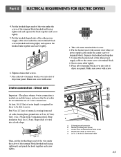
... panel. Strip insulation back 1in. (2.5cm). Squeeze the hooked end together 3. Place tab of terminal block cover into slot of 3-wire connections. External ground connector b. Part 4 ELECTRICAL REQUIREMENTS FOR ELECTRIC DRYERS 4. Put the hooked shape ends of the wire under the center screw of the terminal block(hooked end facing rightward...
... panel. Strip insulation back 1in. (2.5cm). Squeeze the hooked end together 3. Place tab of terminal block cover into slot of 3-wire connections. External ground connector b. Part 4 ELECTRICAL REQUIREMENTS FOR ELECTRIC DRYERS 4. Put the hooked shape ends of the wire under the center screw of the terminal block(hooked end facing rightward...

Owners Manual
Page 17
Part 4 ELECTRICAL REQUIREMENTS FOR ELECTRIC DRYERS Option 1: 3-Wire Connection with a Power Supply Cord lf your local codes or ordinances do not allow the connection of dryer ...
Part 4 ELECTRICAL REQUIREMENTS FOR ELECTRIC DRYERS Option 1: 3-Wire Connection with a Power Supply Cord lf your local codes or ordinances do not allow the connection of dryer ...
Owners Manual
Page 18
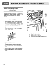
... type 14-30R) b. 4-pront plug c. Ring terminals 1. Remove appliance neutral ground wire (white) from external ground connector screw. External ground connector - Neutral grounding wire (white) f. Part 4 ELECTRICAL REQUIREMENTS FOR ELECTRIC DRYERS Option 2: 4-wire connection with hold-down screw. 17 a. Connect the other wires to external ground conductor screw. Remove center terminal...
... type 14-30R) b. 4-pront plug c. Ring terminals 1. Remove appliance neutral ground wire (white) from external ground connector screw. External ground connector - Neutral grounding wire (white) f. Part 4 ELECTRICAL REQUIREMENTS FOR ELECTRIC DRYERS Option 2: 4-wire connection with hold-down screw. 17 a. Connect the other wires to external ground conductor screw. Remove center terminal...
Owners Manual
Page 19
... b. Grounding path determined by a qualified electrician 4. Tighten screw. 3. b c a d a. Tighten strain relief screws. 5. Neutral grounding wire (white) c. Connect the other wires to an adequate ground. 18 Part 4 ELECTRICAL REQUIREMENTS FOR ELECTRIC DRYERS Option 3: Optional 3-wire connection. • If your local codes or ordinances do not allow the connection of a frame-grounding conductor...
... b. Grounding path determined by a qualified electrician 4. Tighten screw. 3. b c a d a. Tighten strain relief screws. 5. Neutral grounding wire (white) c. Connect the other wires to an adequate ground. 18 Part 4 ELECTRICAL REQUIREMENTS FOR ELECTRIC DRYERS Option 3: Optional 3-wire connection. • If your local codes or ordinances do not allow the connection of a frame-grounding conductor...
Owners Manual
Page 20
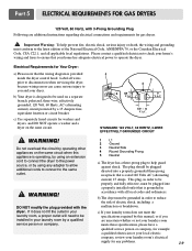
..., polarized, three-wire, effectively grounded, 120 Volt, 60 Hertz, AC (alternating current) circuit protected by a qualified service person or company. 5 1 3 2 4 120 ± 12 V.A.C 0 V.A.C. 120 + 12 V.A.C. Part 5 ELECTRICAL REQUIREMENTS FOR GAS DRYERS 120 Volt, 60 Hertz, with the dryer. Important Warning: To help guard against shock. Label all local codes and ordinances...
..., polarized, three-wire, effectively grounded, 120 Volt, 60 Hertz, AC (alternating current) circuit protected by a qualified service person or company. 5 1 3 2 4 120 ± 12 V.A.C 0 V.A.C. 120 + 12 V.A.C. Part 5 ELECTRICAL REQUIREMENTS FOR GAS DRYERS 120 Volt, 60 Hertz, with the dryer. Important Warning: To help guard against shock. Label all local codes and ordinances...
Owners Manual
Page 21
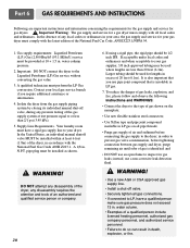
... all gas connections. • If connected to LP, have a rigid gas supply line to the Liquefied Petroleum (LP) Gas service without converting the gas value. 3. Part 6 GAS REQUIREMENTS AND INSTRUCTIONS Following are less than 2/1 psi (3.45 kPa). 5. Gas supply requirements: Liquefied Petroleum (L.P.) Gas (2,500 Btu/ft3 (93.1 MJ/m3)) service must...
... all gas connections. • If connected to LP, have a rigid gas supply line to the Liquefied Petroleum (LP) Gas service without converting the gas value. 3. Part 6 GAS REQUIREMENTS AND INSTRUCTIONS Following are less than 2/1 psi (3.45 kPa). 5. Gas supply requirements: Liquefied Petroleum (L.P.) Gas (2,500 Btu/ft3 (93.1 MJ/m3)) service must...
Owners Manual
Page 22
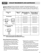
Part 7 EXHAUST REQUIREMENTS AND MAINTENANCE Following are not provided with duct tape. 5. Important Warning: To reduce the risk of fire, combustion, or accumulation of combustible gases, ...
Part 7 EXHAUST REQUIREMENTS AND MAINTENANCE Following are not provided with duct tape. 5. Important Warning: To reduce the risk of fire, combustion, or accumulation of combustible gases, ...

Owners Manual
Page 23
... scrub the lint screen with the brush to the vacuum duct. e) After drying the lint screen with your fingers, wet both sides of the dryer. 8. Part 7 EXHAUST REQUIREMENTS AND MAINTENANCE Exhaust and Dryer Maintenance ! This Kit comes in your dryer. 22 Cleaning the Lint Screen 1. Please clean the lint filter either...
... scrub the lint screen with the brush to the vacuum duct. e) After drying the lint screen with your fingers, wet both sides of the dryer. 8. Part 7 EXHAUST REQUIREMENTS AND MAINTENANCE Exhaust and Dryer Maintenance ! This Kit comes in your dryer. 22 Cleaning the Lint Screen 1. Please clean the lint filter either...


