Service Manual
Page 20
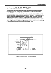
.... The RF3166 requires no external routing or external components, simplifying layout and reducing board space. 3. The RF3166 incorporates RFMD's latest VBATT tracking circuit, which monitors battery voltage and prevents the power control loop From reaching saturation. The device is designed for use as the final RF amplifier in GSM850, EGSM900, DCS... and PCS handheld digital cellular equipment and other applications in the 824MHz to 849MHz, 880MHz to 915MHz, 1710MHz to 1785MHz and 1850MHz to monitor battery voltage, thereby minimizing switching transients.
.... The RF3166 requires no external routing or external components, simplifying layout and reducing board space. 3. The RF3166 incorporates RFMD's latest VBATT tracking circuit, which monitors battery voltage and prevents the power control loop From reaching saturation. The device is designed for use as the final RF amplifier in GSM850, EGSM900, DCS... and PCS handheld digital cellular equipment and other applications in the 824MHz to 849MHz, 880MHz to 915MHz, 1710MHz to 1785MHz and 1850MHz to monitor battery voltage, thereby minimizing switching transients.
Service Manual
Page 21
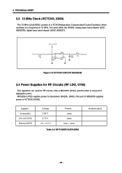
...(X500) consists of a TCXO(Temperature Compensated Crystal Oscillator) which oscillates at a frequency of AD6537B supplies power to transceiver (SI4205, U500). Supplier U702(VRF) U101(VVCXO) Battery(VBAT) Voltage 2.85 V 2.75 V 3.4 ~ 4.2 V Powers U500 X500 U501, U702 Table 3-2 RF POWER SUPPLIERS enabled signal - 20 - MIC5255 (U702) supplies power to VCTCXO (X500). 3. One is...
...(X500) consists of a TCXO(Temperature Compensated Crystal Oscillator) which oscillates at a frequency of AD6537B supplies power to transceiver (SI4205, U500). Supplier U702(VRF) U101(VVCXO) Battery(VBAT) Voltage 2.85 V 2.75 V 3.4 ~ 4.2 V Powers U500 X500 U501, U702 Table 3-2 RF POWER SUPPLIERS enabled signal - 20 - MIC5255 (U702) supplies power to VCTCXO (X500). 3. One is...

Service Manual
Page 23
... BRIEF 3.5 Digital Main Processor (AD6527, U100) Keypad Matrix Backlight/ Service Light Flash 16-bit SRAM 8 or 16 bit (optional) DISPLAY (Parallel) serial display Accessory Devices e.g BATTERY SIM Application Processor USB Host PA Supply Enable AD6527/AD6527B GSM-PROCESSOR KEYPADCOL[7:0] KEYPADROW[7:0] JTAGEN TCK, TMS TDI, TDO BACKLIGHT[3.0] Servicelight JTAG, HSL, GPIO USCTX...
... BRIEF 3.5 Digital Main Processor (AD6527, U100) Keypad Matrix Backlight/ Service Light Flash 16-bit SRAM 8 or 16 bit (optional) DISPLAY (Parallel) serial display Accessory Devices e.g BATTERY SIM Application Processor USB Host PA Supply Enable AD6527/AD6527B GSM-PROCESSOR KEYPADCOL[7:0] KEYPADROW[7:0] JTAGEN TCK, TMS TDI, TDO BACKLIGHT[3.0] Servicelight JTAG, HSL, GPIO USCTX...
Service Manual
Page 28
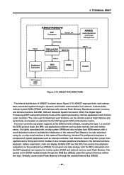
... is shown above Figure 3-10. It is composed of system peripherals such as data services, test and maintenance. The access to the terminal functions: keyboard, battery supervision, radio and display. It also includes peripheral interfaces to the SRAM module ismade through the RAM Bus (RBUS) under the control of AD6527 is...
... is shown above Figure 3-10. It is composed of system peripherals such as data services, test and maintenance. The access to the terminal functions: keyboard, battery supervision, radio and display. It also includes peripheral interfaces to the SRAM module ismade through the RAM Bus (RBUS) under the control of AD6527 is...
Service Manual
Page 29
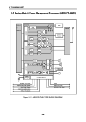
3. TECHNICAL BRIEF 3.6 Analog Main & Power Management Processor (AD6537B, U101) AD6525 or AD6526 BSPORT CSPORT AD6537B Light Controllers Ram GMSK Filter Filter ADC DAC DAC DAC DAC ADC ADC LEDs Othello Crystal & Varactor Tone Filter DAC ASPORT Filter ADC Mic Battery Charger 8 Voltage Regulators Switch Headphones or Headset VCORE: 1.8 V, 80mA VMEM: 1.8 or 2.8V, 150mA VEXT: 2.8V, 170mA VSIM: 1.8 or 2.85V, 20mA VRTC: 1.8V, 200 µA VABB VMIC: 2.5V, 1mA VVCXO: 2.75V, 10mA Figure 3-11 AD6537B FUNCTION BLOCK DIAGRAM - 28 -
3. TECHNICAL BRIEF 3.6 Analog Main & Power Management Processor (AD6537B, U101) AD6525 or AD6526 BSPORT CSPORT AD6537B Light Controllers Ram GMSK Filter Filter ADC DAC DAC DAC DAC ADC ADC LEDs Othello Crystal & Varactor Tone Filter DAC ASPORT Filter ADC Mic Battery Charger 8 Voltage Regulators Switch Headphones or Headset VCORE: 1.8 V, 80mA VMEM: 1.8 or 2.8V, 150mA VEXT: 2.8V, 170mA VSIM: 1.8 or 2.85V, 20mA VRTC: 1.8V, 200 µA VABB VMIC: 2.5V, 1mA VVCXO: 2.75V, 10mA Figure 3-11 AD6537B FUNCTION BLOCK DIAGRAM - 28 -

Service Manual
Page 30
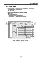
... Filters 3. 3. Auxiliary section • Voltage Reference • Automatic Frequency Control DAC • Auxiliary ADC • Light Controllers 4. Power Management section • Voltage Regulators • Battery Charger • Battery Protection6. AD6537B covers the processing GMSK modulation interface, Aux ADC, Voice signal processing and Power Management. • AD6537B consists of 1. Audio Section • 8 kHz...
... Filters 3. 3. Auxiliary section • Voltage Reference • Automatic Frequency Control DAC • Auxiliary ADC • Light Controllers 4. Power Management section • Voltage Regulators • Battery Charger • Battery Protection6. AD6537B covers the processing GMSK modulation interface, Aux ADC, Voice signal processing and Power Management. • AD6537B consists of 1. Audio Section • 8 kHz...
Service Manual
Page 32
... contains AUX ADC and Voltage Reference • IDAC: 10 bits • The Auxiliary ADC provides : -Two differential inputs for temperature sensing. -A differential input for the battery charger current sensor CSFS CSDI CSDO AD6537B Control Serial Port AFC DAC Voltage Reference Aux ADC REFTXCM Light Controllers AFCDAC REFBB REFOUT REFCHG REF TEMP1...
... contains AUX ADC and Voltage Reference • IDAC: 10 bits • The Auxiliary ADC provides : -Two differential inputs for temperature sensing. -A differential input for the battery charger current sensor CSFS CSDI CSDO AD6537B Control Serial Port AFC DAC Voltage Reference Aux ADC REFTXCM Light Controllers AFCDAC REFBB REFOUT REFCHG REF TEMP1...
Service Manual
Page 34
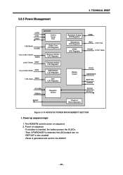
Power on sequence -If a battery is inserted, the battery powers the 8 LDOs. -Then if PWRONKEY is generated and send to the AD6527 - 33 - The AD6537B controls power on . -REFOUT is also enabled -Reset is ... RTC LDO Regulator VCXOEN DBBON RESET Regulator Control Baseband Analog LDO Regulator Microphone LDO Regulator VCXO LDO Regulator VABB VMIC 2.5V, 1mA VVCXO 2.75V, 10mA Battery Charer VCHG GATEDRIVE BATTYPE ISENSE KEYON KEYOUT Power-on Reset Generator Figure 3-16 AD6537B POWER MANAGEMENT SECTION 1. Power up sequence logic 1.
Power on sequence -If a battery is inserted, the battery powers the 8 LDOs. -Then if PWRONKEY is generated and send to the AD6527 - 33 - The AD6537B controls power on . -REFOUT is also enabled -Reset is ... RTC LDO Regulator VCXOEN DBBON RESET Regulator Control Baseband Analog LDO Regulator Microphone LDO Regulator VCXO LDO Regulator VABB VMIC 2.5V, 1mA VVCXO 2.75V, 10mA Battery Charer VCHG GATEDRIVE BATTYPE ISENSE KEYON KEYOUT Power-on Reset Generator Figure 3-16 AD6537B POWER MANAGEMENT SECTION 1. Power up sequence logic 1.
Service Manual
Page 36
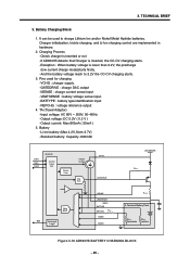
... charging control are implemented in hardware. 2. Pins used to 3.2V the CC-CV charging starts. 3. Battery -Li-ion battery (Max 4.2V, Nom 3.7V) -Standard battery: Capacity -830mAh CSFS CSDI CSDO AD6537B Control Serial Port Charge Timer Trouble Charge Chg. TECHNICAL BRIEF 3. ... used for charging -VCHG : charger supply. -GATEDRIVE : charge DAC output -ISENSE : charge current sense input -VBATSENSE : battery voltage sense input. -BATTYPE : battery type identification input -REFCHG : voltage reference output 4. Charging Process -Check charger is inserted or not -If AD6537B detects that ...
... charging control are implemented in hardware. 2. Pins used to 3.2V the CC-CV charging starts. 3. Battery -Li-ion battery (Max 4.2V, Nom 3.7V) -Standard battery: Capacity -830mAh CSFS CSDI CSDO AD6537B Control Serial Port Charge Timer Trouble Charge Chg. TECHNICAL BRIEF 3. ... used for charging -VCHG : charger supply. -GATEDRIVE : charge DAC output -ISENSE : charge current sense input -VBATSENSE : battery voltage sense input. -BATTYPE : battery type identification input -REFCHG : voltage reference output 4. Charging Process -Check charger is inserted or not -If AD6537B detects that ...
Service Manual
Page 38
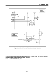
... 3 2 1 IMX9T110 Q301 4 5 6 R353 1K 2012,1% R352 15 R356 47K VBAT C324 0.1u LD306 R350 750 3 2 Q401 2SC5585 1 R358 10K R359 20 Figure 3-21 CIRCUIT FOR BATTERY CHARGING AT AD6537B In order to reduce time for trickle charging, additional circuit(Pre-charge circuit) was included.This circuit has supplied Max 160mA current...
... 3 2 1 IMX9T110 Q301 4 5 6 R353 1K 2012,1% R352 15 R356 47K VBAT C324 0.1u LD306 R350 750 3 2 Q401 2SC5585 1 R358 10K R359 20 Figure 3-21 CIRCUIT FOR BATTERY CHARGING AT AD6537B In order to reduce time for trickle charging, additional circuit(Pre-charge circuit) was included.This circuit has supplied Max 160mA current...
Service Manual
Page 62
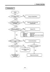
... power-on key And check the level change of PWRKEY YES Check the voltage of The LDO outputs at U101 YES NO Charge or Change Battery NO Check the contact of power key Or dome-switch NO Replace U101 VCORE=1.8V VMEM=2.8V VEXT=2.8V VABB=2.75V WCXO=2.75V VRTC=1.8V... inserted) VMIC=2.5V NO Logic level at KEYON of U101 = HIGH YES NO Does it work properly? 4 . Re-download software Does it work properly? Check Battery Voltage > 3.35V ? Replace the main board - 61 -
... power-on key And check the level change of PWRKEY YES Check the voltage of The LDO outputs at U101 YES NO Charge or Change Battery NO Check the contact of power key Or dome-switch NO Replace U101 VCORE=1.8V VMEM=2.8V VEXT=2.8V VABB=2.75V WCXO=2.75V VRTC=1.8V... inserted) VMIC=2.5V NO Logic level at KEYON of U101 = HIGH YES NO Does it work properly? 4 . Re-download software Does it work properly? Check Battery Voltage > 3.35V ? Replace the main board - 61 -
Service Manual
Page 64
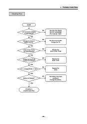
YES Q100, D100, R108 are well-soldered? NO The battery may have problems. Change the battery. Replace the Q100 YES Battery is properly operating - 63 - Checking Flow 4 . YES Charging is charged? Replace the Q100, D100 YES NO 0.7 < voltage(R109) < 1.3V? TROUBLE SHOOTING START I/O Connector (CN300) is about 10~100mV? NO Resolder the CN300 Pin 4,5 : VCHARGE Pin 12,26.30 : GND NO The TA is out of D100 = 5.2 V? YES Voltage at anode of order Change the TA NO Resoler the Q100, D100, R108 YES NO Voltage across R108 is well-solderd?
YES Q100, D100, R108 are well-soldered? NO The battery may have problems. Change the battery. Replace the Q100 YES Battery is properly operating - 63 - Checking Flow 4 . YES Charging is charged? Replace the Q100, D100 YES NO 0.7 < voltage(R109) < 1.3V? TROUBLE SHOOTING START I/O Connector (CN300) is about 10~100mV? NO Resolder the CN300 Pin 4,5 : VCHARGE Pin 12,26.30 : GND NO The TA is out of D100 = 5.2 V? YES Voltage at anode of order Change the TA NO Resoler the Q100, D100, R108 YES NO Voltage across R108 is well-solderd?
Service Manual
Page 78
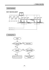
YES Charge battery Are all LEDs Working? TROUBLE SHOOTING CIRCUIT DIAGRAM KEY BACKLIGHT VBAT C318 1u C319 1u C320 1u C323 1u C321 1u C322 1u R344 47 R345 47 R346 47 R347 47 R348 47 R349 47 LEBB-S14H LD300 LD302 LD301 LEBB-S14H LEBB-S14H LD303 LEBB-S14H LD304 LD305 LEBB-S14H LEBB-S14H MIDI_KEY_BL1 MIDI_KEY_BL2 Checking Flow START NO Is the voltage level VBAT 3.6~4.2V? NO Check the soldering each R and LED YES Backlight will work properly NO Replace or resoldering component - 77 - 4 .
YES Charge battery Are all LEDs Working? TROUBLE SHOOTING CIRCUIT DIAGRAM KEY BACKLIGHT VBAT C318 1u C319 1u C320 1u C323 1u C321 1u C322 1u R344 47 R345 47 R346 47 R347 47 R348 47 R349 47 LEBB-S14H LD300 LD302 LD301 LEBB-S14H LEBB-S14H LD303 LEBB-S14H LD304 LD305 LEBB-S14H LEBB-S14H MIDI_KEY_BL1 MIDI_KEY_BL2 Checking Flow START NO Is the voltage level VBAT 3.6~4.2V? NO Check the soldering each R and LED YES Backlight will work properly NO Replace or resoldering component - 77 - 4 .
Service Manual
Page 108
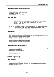
.... Call-setup equipment is to Digital Converter) This displays the value of each ADC. 1) MVBAT ADC : Main Voltage Battery ADC 2) AUX ADC : Auxiliary ADC 3) TEMPER ADC : Temperature ADC 9.1.7 BATTERY 1) Bat Cal : This displays the value of VoicebandBaseband Codec chip.Although the actual value can be written over, it returns to default value...
.... Call-setup equipment is to Digital Converter) This displays the value of each ADC. 1) MVBAT ADC : Main Voltage Battery ADC 2) AUX ADC : Auxiliary ADC 3) TEMPER ADC : Temperature ADC 9.1.7 BATTERY 1) Bat Cal : This displays the value of VoicebandBaseband Codec chip.Although the actual value can be written over, it returns to default value...

Service Manual
Page 114
... Setting : Load saved Calibration setting -File(F) Make BIN ALL : Make binary file after calibration finished -File(F) Make BIN BAT.Cal only : Make binary file of battery cal data only after calibration finished -File(F) Make & Write BIN : Make binary file after calibration finished then download it performs sync. AUTO CALIBRATION 11.1 Overview.... -GPIB(G) Connect : Connect the Ag8960 GPIB card with Agilent 8960(GSM call setting instrument) and Tektronix PS2521G(Programmable Power supply). After that performTx,Rx and Battery Calibration with PC. - 113 - AUTO CALIBRATION 11.
... Setting : Load saved Calibration setting -File(F) Make BIN ALL : Make binary file after calibration finished -File(F) Make BIN BAT.Cal only : Make binary file of battery cal data only after calibration finished -File(F) Make & Write BIN : Make binary file after calibration finished then download it performs sync. AUTO CALIBRATION 11.1 Overview.... -GPIB(G) Connect : Connect the Ag8960 GPIB card with Agilent 8960(GSM call setting instrument) and Tektronix PS2521G(Programmable Power supply). After that performTx,Rx and Battery Calibration with PC. - 113 - AUTO CALIBRATION 11.
Service Manual
Page 116
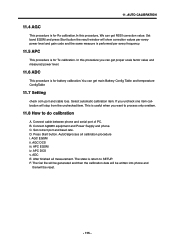
... show correction values per every power level and gain code and the same measure is performed per every frequency. 11.5 APC This procedure is for battery calibration.You can get main Battery Config Table and temperature ConfigTable 11.7 Setting check com port and cable loss. 11. B. AGC DCS iii. APC EGSM iv.
... show correction values per every power level and gain code and the same measure is performed per every frequency. 11.5 APC This procedure is for battery calibration.You can get main Battery Config Table and temperature ConfigTable 11.7 Setting check com port and cable loss. 11. B. AGC DCS iii. APC EGSM iv.
Service Manual
Page 120
12. Description GSM,BAR/FILP 2 AAAY ADDITION 3 MCJA COVER,BATTERY 2 APEY PHONE 3 ACGK COVER ASSY,FRONT 4 AWAB00 WINDOW ASSY,LCD 5 BFAA00 FILM,INMOLD 5 MWAC WINDOW,LCD 4 MCCC00 CAP,EARPHONE JACK 4 MCJK COVER,FRONT 4 MICZ INSERT 4 ...
12. Description GSM,BAR/FILP 2 AAAY ADDITION 3 MCJA COVER,BATTERY 2 APEY PHONE 3 ACGK COVER ASSY,FRONT 4 AWAB00 WINDOW ASSY,LCD 5 BFAA00 FILM,INMOLD 5 MWAC WINDOW,LCD 4 MCCC00 CAP,EARPHONE JACK 4 MCJK COVER,FRONT 4 MICZ INSERT 4 ...

Service Manual
Page 121
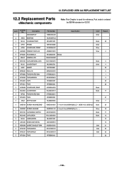
... 19 8 - 120 - 12. Description SUSY00 SPEAKER 4 SJMY00 VIBRATOR,MOTOR 3 SAFY00 PCB ASSY,MAIN 4 SAFB PCB ASSY,MAIN,INSERT 5 SBCL00 BATTERY,CELL,LITHIUM 5 SUMY00 MICROPHONE 5 SVLY00 LCD 4 SAFF00 PCB ASSY,MAIN,SMT 5 MLAB00 LABEL,A/S 5 MLAC00 LABEL,BARCODE 5 SAFC00 PCB ASSY,MAIN,...PIN ,8 ohm,88 dB,20 mm,*14mm SJMY0007001 3 V,0.085 A,4*12.5 ,6.6T,L3100,SILINDER SAFY0125201 B2050 PCB ASSY MAIN SAFB0040301 B2000/B2050 MAIN INSERT SBCL0001303 2 V,1 mAh,COIN ,SOLDER TYPE BACKUP BATTERY SUMY0003802 FPCB ,-42 dB,4*1.5 , SVLY0025501 MAIN ,128*128 ,35.78*39.7 ,65k ,CSTN ,...
... 19 8 - 120 - 12. Description SUSY00 SPEAKER 4 SJMY00 VIBRATOR,MOTOR 3 SAFY00 PCB ASSY,MAIN 4 SAFB PCB ASSY,MAIN,INSERT 5 SBCL00 BATTERY,CELL,LITHIUM 5 SUMY00 MICROPHONE 5 SVLY00 LCD 4 SAFF00 PCB ASSY,MAIN,SMT 5 MLAB00 LABEL,A/S 5 MLAC00 LABEL,BARCODE 5 SAFC00 PCB ASSY,MAIN,...PIN ,8 ohm,88 dB,20 mm,*14mm SJMY0007001 3 V,0.085 A,4*12.5 ,6.6T,L3100,SILINDER SAFY0125201 B2050 PCB ASSY MAIN SAFB0040301 B2000/B2050 MAIN INSERT SBCL0001303 2 V,1 mAh,COIN ,SOLDER TYPE BACKUP BATTERY SUMY0003802 FPCB ,-42 dB,4*1.5 , SVLY0025501 MAIN ,128*128 ,35.78*39.7 ,65k ,CSTN ,...
Service Manual
Page 131
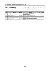
12. EXPLODED VIEW && REPLACEMENT PART LIST 12.3 Accessory Note: This Chapter is used for reference, Part order is ordered by SBOM standard on GCSC Location Level No. Description 3 SBPL00 BATTERY PACK,LI-ION 3 SSAD00 ADAPTOR,AC-DC 3 WSAY00 SOFTWARE,APPLICATION 3 WSYY00 SOFTWARE Part Number Specification SBPL0077901 3.7 V,830 mAh,1 CELL,PRISMATIC ,FG101 RUSSV423450, Innerpack SSAD0007835 FREE ,50 Hz,5.2 V,800 mA,CE,CB ,UK(IO.24P) WSAY0014101 B2050 TMU PC-Sync WSYY0239601 B2050P40FL-44-V101-234-30 APR 13 2005+1@ B2050 TMU S/W Color Remark - 130 -
12. EXPLODED VIEW && REPLACEMENT PART LIST 12.3 Accessory Note: This Chapter is used for reference, Part order is ordered by SBOM standard on GCSC Location Level No. Description 3 SBPL00 BATTERY PACK,LI-ION 3 SSAD00 ADAPTOR,AC-DC 3 WSAY00 SOFTWARE,APPLICATION 3 WSYY00 SOFTWARE Part Number Specification SBPL0077901 3.7 V,830 mAh,1 CELL,PRISMATIC ,FG101 RUSSV423450, Innerpack SSAD0007835 FREE ,50 Hz,5.2 V,800 mA,CE,CB ,UK(IO.24P) WSAY0014101 B2050 TMU PC-Sync WSYY0239601 B2050P40FL-44-V101-234-30 APR 13 2005+1@ B2050 TMU S/W Color Remark - 130 -

