Service Manual
Page 2
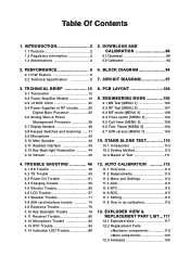
TROUBLE SHOOTING 46 4.1 RX Trouble 46 4.2 TX Trouble 53 4.3 Power On Trouble 61 4.4 Charging Trouble 63 4.5 Vibrator Trouble 65 4.6 LCD Trouble 67 4.7 Speaker Trouble 71 4.8 SIM card interface trouble 74 4.9 Earphone Trouble 76 4.10 Key Backlight Trouble 78 4.11 Receiver Trouble 80 4.12 Microphone Trouble 82 4.13 RTC Trouble 84 4.14 Indication LED Trouble 86 12. EXPLODED VIEW & REPLACEMENT PART LIST ...117 12.1 Exploded View 117 12.2 Replacement Parts PCB LAYOUT 102 9. Reset [MENU 6 109 9.7 S/W version [MENU 7 109 10. Table Of Contents 1. DOWNLOAD AND CALIBRATION...
TROUBLE SHOOTING 46 4.1 RX Trouble 46 4.2 TX Trouble 53 4.3 Power On Trouble 61 4.4 Charging Trouble 63 4.5 Vibrator Trouble 65 4.6 LCD Trouble 67 4.7 Speaker Trouble 71 4.8 SIM card interface trouble 74 4.9 Earphone Trouble 76 4.10 Key Backlight Trouble 78 4.11 Receiver Trouble 80 4.12 Microphone Trouble 82 4.13 RTC Trouble 84 4.14 Indication LED Trouble 86 12. EXPLODED VIEW & REPLACEMENT PART LIST ...117 12.1 Exploded View 117 12.2 Replacement Parts PCB LAYOUT 102 9. Reset [MENU 6 109 9.7 S/W version [MENU 7 109 10. Table Of Contents 1. DOWNLOAD AND CALIBRATION...
Service Manual
Page 3
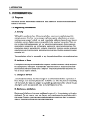
... from such unauthorized use of common-carrier telecommunication service of facilities accessed throughor connected to repair, calibration, description and download the features of telecommunications system byan unauthorized part (for your company's employees, agents, subcontractors, or person working on this manual. System users are responsible for programming and configuring the equipment to affect the use of the system and may make any remaining warranty...
... from such unauthorized use of common-carrier telecommunication service of facilities accessed throughor connected to repair, calibration, description and download the features of telecommunications system byan unauthorized part (for your company's employees, agents, subcontractors, or person working on this manual. System users are responsible for programming and configuring the equipment to affect the use of the system and may make any remaining warranty...
Service Manual
Page 4
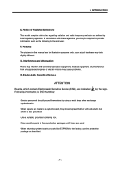
... is also grounded. •Use a suitable, grounded soldering iron. •Keep sensitive parts in this manual are used. •When returning system boards or parts like EEPROM to the end user. Electrostatic Sensitive Devices ATTENTION Boards, which contain Electrostatic Sensitive Device (ESD), are indicated Following information is ESD handling: by the sign. •Service personnel should ground themselves by...
... is also grounded. •Use a suitable, grounded soldering iron. •Keep sensitive parts in this manual are used. •When returning system boards or parts like EEPROM to the end user. Electrostatic Sensitive Devices ATTENTION Boards, which contain Electrostatic Sensitive Device (ESD), are indicated Following information is ESD handling: by the sign. •Service personnel should ground themselves by...
Service Manual
Page 5
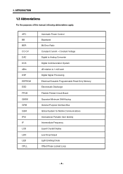
... Power Control Baseband Bit Error Ratio Constant Current - Constant Voltage Digital to Analog Converter Digital Communication System dB relative to 1 milli watt Digital Signal Processing Electrical Erasable Programmable Read-Only Memory Electrostatic Discharge Flexible Printed Circuit Board Gaussian Minimum Shift Keying General Purpose Interface Bus Global System for Mobile Communications International Portable User Identity Intermediate Frequency Liquid Crystal Display...
... Power Control Baseband Bit Error Ratio Constant Current - Constant Voltage Digital to Analog Converter Digital Communication System dB relative to 1 milli watt Digital Signal Processing Electrical Erasable Programmable Read-Only Memory Electrostatic Discharge Flexible Printed Circuit Board Gaussian Minimum Shift Keying General Purpose Interface Bus Global System for Mobile Communications International Portable User Identity Intermediate Frequency Liquid Crystal Display...
Service Manual
Page 6
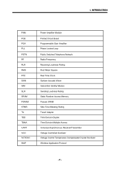
... Board Programmable Gain Amplifier Phase Locked Loop Public Switched Telephone Network Radio Frequency Receiving Loudness Rating Root Mean Square Real Time Clock Surface Acoustic Wave Subscriber Identity Module Sending Loudness Rating Static Random Access Memory Pseudo SRAM Side Tone Masking Rating Travel Adapter Time Division Duplex Time Division Multiple Access Universal Asynchronous Receiver/Transmitter Voltage Controlled Oscillator Voltage Control Temperature Compensated Crystal Oscillator Wireless Application Protocol -5- 1.
... Board Programmable Gain Amplifier Phase Locked Loop Public Switched Telephone Network Radio Frequency Receiving Loudness Rating Root Mean Square Real Time Clock Surface Acoustic Wave Subscriber Identity Module Sending Loudness Rating Static Random Access Memory Pseudo SRAM Side Tone Masking Rating Travel Adapter Time Division Duplex Time Division Multiple Access Universal Asynchronous Receiver/Transmitter Voltage Controlled Oscillator Voltage Control Temperature Compensated Crystal Oscillator Wireless Application Protocol -5- 1.

Service Manual
Page 23
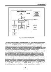
.../ Service Light Flash 16-bit SRAM 8 or 16 bit (optional) DISPLAY (Parallel) serial display Accessory Devices e.g BATTERY SIM Application Processor USB Host PA Supply Enable AD6527/AD6527B GSM-PROCESSOR KEYPADCOL[7:0] KEYPADROW[7:0] JTAGEN TCK, TMS TDI, TDO BACKLIGHT[3.0] Servicelight JTAG, HSL, GPIO USCTX/RX/CLK Enhaoced Generic serial port A Generic serial port B ROMCS[1:0] Generic serial port D ADD[24:0] DATA[15:0] PWRON RESET RAMCS...
.../ Service Light Flash 16-bit SRAM 8 or 16 bit (optional) DISPLAY (Parallel) serial display Accessory Devices e.g BATTERY SIM Application Processor USB Host PA Supply Enable AD6527/AD6527B GSM-PROCESSOR KEYPADCOL[7:0] KEYPADROW[7:0] JTAGEN TCK, TMS TDI, TDO BACKLIGHT[3.0] Servicelight JTAG, HSL, GPIO USCTX/RX/CLK Enhaoced Generic serial port A Generic serial port B ROMCS[1:0] Generic serial port D ADD[24:0] DATA[15:0] PWRON RESET RAMCS...
Service Manual
Page 24
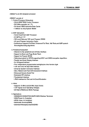
...; 16-bit Fixed Point DSP Processor • 91 MIPS at 1.7V • On-board 16KB instruction/Data Cache • 1 Mbitsof on -chip peripheral and off-chip interface: • Support for Burst and Page Mode Flash • Support for Pseudo SRAM • Ciphering module for GPRS supporting GAE1 and GAE2 encryption algorithms • Parallel and Serial Display Interface • 8 x 8 Keypad Interface...
...; 16-bit Fixed Point DSP Processor • 91 MIPS at 1.7V • On-board 16KB instruction/Data Cache • 1 Mbitsof on -chip peripheral and off-chip interface: • Support for Burst and Page Mode Flash • Support for Pseudo SRAM • Ciphering module for GPRS supporting GAE1 and GAE2 encryption algorithms • Parallel and Serial Display Interface • 8 x 8 Keypad Interface...
Service Manual
Page 27
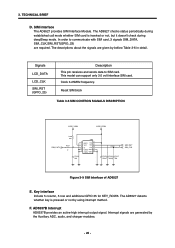
... generated by bellow Table 3-6 in detail. This model can support only 3.0 volt interface SIM card. SIM interface The AD6527 provides SIM Interface Module. Signals LCD_DATA LCD_CLK SIM_RST (GPIO_23) Description This pin receives and sends data to communicate with SIM card, 3 signals SIM_DATA, SIM_CLK,SIM_RST(GPIO_23) are required. 3. TECHNICAL BRIEF D. In order to SIM card. Clock 3.25MHz frequency. Key interface Include 5 column, 5 row and additional GPIO 35 for KEY_ROW5...
... generated by bellow Table 3-6 in detail. This model can support only 3.0 volt interface SIM card. SIM interface The AD6527 provides SIM Interface Module. Signals LCD_DATA LCD_CLK SIM_RST (GPIO_23) Description This pin receives and sends data to communicate with SIM card, 3 signals SIM_DATA, SIM_CLK,SIM_RST(GPIO_23) are required. 3. TECHNICAL BRIEF D. In order to SIM card. Clock 3.25MHz frequency. Key interface Include 5 column, 5 row and additional GPIO 35 for KEY_ROW5...
Service Manual
Page 28
... system SRAM and external memory such Flash Memory. Boththe DSP and the MCU can access the peripheral subsystem via code download using the on-chip serial interface to facilitate the initialization of the external Flash Memory via the peripheral bus (PBUS).For program and data storage, both the MCU subsystem and the DSPsubsystem can be storedin external Flash Memory and dynamically downloaded on -chip system...
... system SRAM and external memory such Flash Memory. Boththe DSP and the MCU can access the peripheral subsystem via code download using the on-chip serial interface to facilitate the initialization of the external Flash Memory via the peripheral bus (PBUS).For program and data storage, both the MCU subsystem and the DSPsubsystem can be storedin external Flash Memory and dynamically downloaded on -chip system...
Service Manual
Page 39
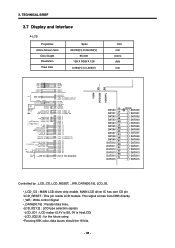
... Signal •_DATA[00:15] : Parallel data lines. •LCD_ID[1:2] : LCD type selection signals -LCD_ID1 : LCD maker (2.4V is SII, 0V is HyeLCD) -LCD_ID[2:3] : for the future using •Forusing 65K color, data buses should be 16 bits. - 38 - MAIN LCD driver IC has own CS pin •LCD_RESET : This pin resets LCD module. TECHNICAL BRIEF 3.7 Display and Interface LCD Properties Active Screen...
... Signal •_DATA[00:15] : Parallel data lines. •LCD_ID[1:2] : LCD type selection signals -LCD_ID1 : LCD maker (2.4V is SII, 0V is HyeLCD) -LCD_ID[2:3] : for the future using •Forusing 65K color, data buses should be 16 bits. - 38 - MAIN LCD driver IC has own CS pin •LCD_RESET : This pin resets LCD module. TECHNICAL BRIEF 3.7 Display and Interface LCD Properties Active Screen...
Service Manual
Page 62
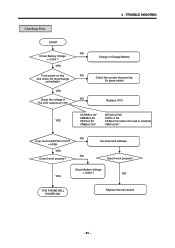
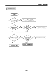
... Change Battery NO Check the contact of power key Or dome-switch NO Replace U101 VCORE=1.8V VMEM=2.8V VEXT=2.8V VABB=2.75V WCXO=2.75V VRTC=1.8V VSIM=2.5V (when sim card is inserted) VMIC=2.5V NO Logic level at KEYON of U101 = HIGH YES NO Does it work properly? NO YES THE PHONE WILL POWER ON. TROUBLE SHOOTING Checking Flow START Check Battery Voltage > 3.35V ? Check Battery Voltage > 3.35V ? Re-download software...
... Change Battery NO Check the contact of power key Or dome-switch NO Replace U101 VCORE=1.8V VMEM=2.8V VEXT=2.8V VABB=2.75V WCXO=2.75V VRTC=1.8V VSIM=2.5V (when sim card is inserted) VMIC=2.5V NO Logic level at KEYON of U101 = HIGH YES NO Does it work properly? NO YES THE PHONE WILL POWER ON. TROUBLE SHOOTING Checking Flow START Check Battery Voltage > 3.35V ? Check Battery Voltage > 3.35V ? Re-download software...
Service Manual
Page 66
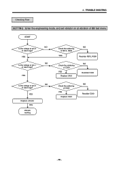
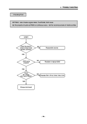
YES Replace vrbrator YES Vibrator working Check the soldering of R315, R399 YES NO Resolder R315, R399 Check the soldering of C300 YES Replace U401 NO Resolder C300 Check the soldering of U401 high? 4 . YES NO Is the voltage at pin 1 of C300 YES Replace U401 NO Resolder C300 - 65 - YES NO Is the voltage at pin 3 of U401 high? TROUBLE SHOOTING Checking Flow SETTING : Enter the engineering mode, and set vibrator on at vibration of BB test menu START NO Is the voltage at pin 5 of U401 high?
YES Replace vrbrator YES Vibrator working Check the soldering of R315, R399 YES NO Resolder R315, R399 Check the soldering of C300 YES Replace U401 NO Resolder C300 Check the soldering of U401 high? 4 . YES NO Is the voltage at pin 1 of C300 YES Replace U401 NO Resolder C300 - 65 - YES NO Is the voltage at pin 3 of U401 high? TROUBLE SHOOTING Checking Flow SETTING : Enter the engineering mode, and set vibrator on at vibration of BB test menu START NO Is the voltage at pin 5 of U401 high?

Service Manual
Page 69
... OK? TROUBLE SHOOTING Checking Flow START Insert Earmic to 4.10 Earphone Trouble Check YES Soldering Component Around U701 OK? Resolder R421 YES Set the audio part of L202 & C219 YES NO Resolder L202 & C219 Change main board - 68 - Level 1,2,8,9 pin Of U700 is OK? YES Resolder the component Change U700 NO Resolder the component Check U205 works properly YES NO Change U205 Change U701 Check Soldering...
... OK? TROUBLE SHOOTING Checking Flow START Insert Earmic to 4.10 Earphone Trouble Check YES Soldering Component Around U701 OK? Resolder R421 YES Set the audio part of L202 & C219 YES NO Resolder L202 & C219 Change main board - 68 - Level 1,2,8,9 pin Of U700 is OK? YES Resolder the component Change U700 NO Resolder the component Check U205 works properly YES NO Change U205 Change U701 Check Soldering...
Service Manual
Page 74
NO Change the SIM Card. YES Voltage at pin1 of J300 is 3V? Does it work Properly? Our Phone supports only 3V SIM card YES NO Voltage at VSIM of components NO Change the SIM Card And try again. Redownload SW. TROUBLE SHOOTING START Does the SIM cards supports 3V? Does it work Properly? NO Change the main board YES Change SIM Card YES SIM Card will be detected - 73 - NO YES Replace J300 or check soldering of U101 Is 3V? Checking Flow 4 .
NO Change the SIM Card. YES Voltage at pin1 of J300 is 3V? Does it work Properly? Our Phone supports only 3V SIM card YES NO Voltage at VSIM of components NO Change the SIM Card And try again. Redownload SW. TROUBLE SHOOTING START Does the SIM cards supports 3V? Does it work Properly? NO Change the main board YES Change SIM Card YES SIM Card will be detected - 73 - NO YES Replace J300 or check soldering of U101 Is 3V? Checking Flow 4 .
Service Manual
Page 80
Checking Flow 4 . NO Resolder or replace U202 YES Check the voltage at 5,7 pin of dual mode speaker (receiver) YES Reassemble receiver U202 works properly? START Check the state of NO contact of U202? TROUBLE SHOOTING SETTING : After initialize Agilent 8960, Test EGSM, DCS mode Set the property of mobile as PRBS or continuous wave. YES Change main board NO Resolder R111, R114, C139, C140, C141 - 79 - Set the receiving volume of audio as Max.
Checking Flow 4 . NO Resolder or replace U202 YES Check the voltage at 5,7 pin of dual mode speaker (receiver) YES Reassemble receiver U202 works properly? START Check the state of NO contact of U202? TROUBLE SHOOTING SETTING : After initialize Agilent 8960, Test EGSM, DCS mode Set the property of mobile as PRBS or continuous wave. YES Change main board NO Resolder R111, R114, C139, C140, C141 - 79 - Set the receiving volume of audio as Max.
Service Manual
Page 107
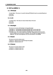
... 9.1.3 Backlight This menu is displayed. When entering into the menu,the present backlight-value in the NVRAM. 9.1.4 Buzzer This menu is to test the melody sound. 1) Melody on : Melody sound is played through the speaker. 2) Melody off : Melody sound is off. 9.1.5 Vibrator This menu is to test the vibration mode. 1) Vibrator on : Vibration mode is on at the same time. 2) Backlight off : LCD Backlight and Keypad Backlight light off...
... 9.1.3 Backlight This menu is displayed. When entering into the menu,the present backlight-value in the NVRAM. 9.1.4 Buzzer This menu is to test the melody sound. 1) Melody on : Melody sound is played through the speaker. 2) Melody off : Melody sound is off. 9.1.5 Vibrator This menu is to test the vibration mode. 1) Vibrator on : Vibration mode is on at the same time. 2) Backlight off : LCD Backlight and Keypad Backlight light off...
Service Manual
Page 110
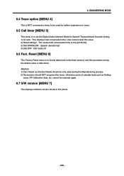
... set up the default value in data block. Attention 1) Fact. Reset (i.e.Factory Reset) should be restored again. 9.7 S/W version [MENU 7] This displays software version stored in the flash memory and this procedure set the Digital Audio Interface Mode for Speech Transcoderand Acoustic testing. 1) All calls : This displays total conversation time. User cannot reset this value. 2) Reset settings : This resets total conversation time to format data block in the phone. - 109 - 9. ENGINEERING MODE 9.4 Trace option [MENU 4] This is NOT a necessary menu to be used...
... set up the default value in data block. Attention 1) Fact. Reset (i.e.Factory Reset) should be restored again. 9.7 S/W version [MENU 7] This displays software version stored in the flash memory and this procedure set the Digital Audio Interface Mode for Speech Transcoderand Acoustic testing. 1) All calls : This displays total conversation time. User cannot reset this value. 2) Reset settings : This resets total conversation time to format data block in the phone. - 109 - 9. ENGINEERING MODE 9.4 Trace option [MENU 4] This is NOT a necessary menu to be used...

Service Manual
Page 114
.../XP -Auto Calibration program(Autocal.exe) -GSM Phone -LGE PIF JIG, Serial Cable, Data Cable -Agilent 8960(Call Setting Instrument) -Tektronix PS2521G(Programmable Power Supply) 11.3 Menu and Settings -File(F) Clear View : Clear Calibration Status window texts -File(F) Save View : Save Calibration Status window texts -File(F) Save Setting : Save Current Calibration settings to setting file(*.cal) -File(F) Load Setting : Load saved Calibration setting -File(F) Make BIN ALL : Make binary file after calibration finished -File(F) Make BIN BAT.Cal only : Make binary file of battery cal data only...
.../XP -Auto Calibration program(Autocal.exe) -GSM Phone -LGE PIF JIG, Serial Cable, Data Cable -Agilent 8960(Call Setting Instrument) -Tektronix PS2521G(Programmable Power Supply) 11.3 Menu and Settings -File(F) Clear View : Clear Calibration Status window texts -File(F) Save View : Save Calibration Status window texts -File(F) Save Setting : Save Current Calibration settings to setting file(*.cal) -File(F) Load Setting : Load saved Calibration setting -File(F) Make BIN ALL : Make binary file after calibration finished -File(F) Make BIN BAT.Cal only : Make binary file of battery cal data only...
Service Manual
Page 116
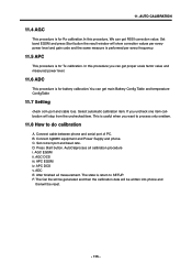
... iii. The Cal file will be generated and then the calibration data will stop from the unchecked item. D. Press Start button. The state is useful when you can get proper scale factor value and measured power level. 11.6 ADC This procedure is for battery calibration.You can get main Battery Config Table and temperature ConfigTable 11.7 Setting check com port and...
... iii. The Cal file will be generated and then the calibration data will stop from the unchecked item. D. Press Start button. The state is useful when you can get proper scale factor value and measured power level. 11.6 ADC This procedure is for battery calibration.You can get main Battery Config Table and temperature ConfigTable 11.7 Setting check com port and...

Service Manual
Page 121
... VIEW && REPLACEMENT PART LIST 12.2 Replacement Parts Note: This Chapter is used for PCB ASSY MAIN(hardware)) SAFC0048101 B2050 PCB... 16 16 19 8 - 120 - Description SUSY00 SPEAKER 4 SJMY00 VIBRATOR,MOTOR 3 SAFY00 PCB ASSY,MAIN 4 SAFB PCB ASSY,MAIN,INSERT 5 SBCL00 BATTERY,CELL,LITHIUM 5 SUMY00 MICROPHONE 5 SVLY00 LCD 4 SAFF00 PCB...Part Number Specification SUSY0014801 PIN ,8 ohm,88 dB,20 mm,*14mm SJMY0007001 3 V,0.085 A,4*12.5 ,6.6T,L3100,SILINDER SAFY0125201 B2050 PCB ASSY MAIN SAFB0040301 B2000/B2050 MAIN INSERT SBCL0001303 2 V,1 mAh,COIN ,SOLDER TYPE BACKUP BATTERY ...
... VIEW && REPLACEMENT PART LIST 12.2 Replacement Parts Note: This Chapter is used for PCB ASSY MAIN(hardware)) SAFC0048101 B2050 PCB... 16 16 19 8 - 120 - Description SUSY00 SPEAKER 4 SJMY00 VIBRATOR,MOTOR 3 SAFY00 PCB ASSY,MAIN 4 SAFB PCB ASSY,MAIN,INSERT 5 SBCL00 BATTERY,CELL,LITHIUM 5 SUMY00 MICROPHONE 5 SVLY00 LCD 4 SAFF00 PCB...Part Number Specification SUSY0014801 PIN ,8 ohm,88 dB,20 mm,*14mm SJMY0007001 3 V,0.085 A,4*12.5 ,6.6T,L3100,SILINDER SAFY0125201 B2050 PCB ASSY MAIN SAFB0040301 B2000/B2050 MAIN INSERT SBCL0001303 2 V,1 mAh,COIN ,SOLDER TYPE BACKUP BATTERY ...


