
Owners Manual
Page 2
...). NO USER SERVICEABLE PARTS INSIDE. The lightning flash with the instructions, may cause harmful interference to provide reasonable protection against harmful interference in any way without written authorization from that may be connected to the grounding system of the building, as practical. Reorient or relocate the receiving antenna. - Any changes or modifications not expressly approved by turning the equipment...
...). NO USER SERVICEABLE PARTS INSIDE. The lightning flash with the instructions, may cause harmful interference to provide reasonable protection against harmful interference in any way without written authorization from that may be connected to the grounding system of the building, as practical. Reorient or relocate the receiving antenna. - Any changes or modifications not expressly approved by turning the equipment...
Owners Manual
Page 5
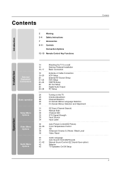
... Out Setup Digital Audio Output PC Setup 29 29 29 29 30 31 31 32 33 33 34 35 35~36 37 38 39 40 41 41~42 43 43 Turning on the TV Volume Adjustment Channel Selection On Screen Menus Language Selection On Screen Menus Selection and Adjustment EZ Scan (Channel Search) Manual Scan Channel Edit DTV Signal Strength Input Source Input Label Auto Picture Control(EZ Picture) Color Temperature Control XD Advanced-Cinema 3:2 Mode / Black Level Video Reset Audio Language Auto Sound Control(EZ Sound) Manual Sound Control (EZ Sound-User...
... Out Setup Digital Audio Output PC Setup 29 29 29 29 30 31 31 32 33 33 34 35 35~36 37 38 39 40 41 41~42 43 43 Turning on the TV Volume Adjustment Channel Selection On Screen Menus Language Selection On Screen Menus Selection and Adjustment EZ Scan (Channel Search) Manual Scan Channel Edit DTV Signal Strength Input Source Input Label Auto Picture Control(EZ Picture) Color Temperature Control XD Advanced-Cinema 3:2 Mode / Black Level Video Reset Audio Language Auto Sound Control(EZ Sound) Manual Sound Control (EZ Sound-User...

Owners Manual
Page 9
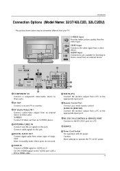
...power. AUDIO IN (RGB/DVI) Connect the monitor output from an S-VIDEO device. 4 ANTENNA/CABLE IN Connect over-the air signals to this jack. S-VIDEO Input AV IN 2 Provides better picture quality than the video input. S-VIDEO VIDEO ( ) AUDIO 9 S-VIDEO VIDEO ( ) AUDIO AUDIO COMPONENT IN AV OUT AV IN 1 COMPONENT IN AV OUT AV IN 1 6 HDMI IN VIDEO AUDIO Connect a HDMI signal to operate the TV on a PC. 10 SERVICE 11 Power Cord Socket For operation with a DVI to these ports do notVwIDEOork. 8 Remote Control Port Connect your TV. Connect cable signals to this jack. 5 DIGITAL...
...power. AUDIO IN (RGB/DVI) Connect the monitor output from an S-VIDEO device. 4 ANTENNA/CABLE IN Connect over-the air signals to this jack. S-VIDEO Input AV IN 2 Provides better picture quality than the video input. S-VIDEO VIDEO ( ) AUDIO 9 S-VIDEO VIDEO ( ) AUDIO AUDIO COMPONENT IN AV OUT AV IN 1 COMPONENT IN AV OUT AV IN 1 6 HDMI IN VIDEO AUDIO Connect a HDMI signal to operate the TV on a PC. 10 SERVICE 11 Power Cord Socket For operation with a DVI to these ports do notVwIDEOork. 8 Remote Control Port Connect your TV. Connect cable signals to this jack. 5 DIGITAL...
Owners Manual
Page 11
...VIDEO Input Connects the video signal from an external device to AC IN stereo sound from an external device. 11 10 1 SERVICE 7 COMPONENT IN 6 RGB IN (PC) VIDEO AUDIO 5 AV OUT AV IN 1 COMPONENT IN 4 HDMI IN 2 8 VIDEO AUDIO 2 ANTENNA/ 1(DVI) OPTICAL CABLE IN RS-232C IN (CONTROL & SERVICE) DIGITAL AUDIO OUT S-VIDEO VIDEO (MONO) AUDIO 3 AV OUT 1 COMPONENT IN Connect a component these ports do not work. 8 Remote Control Port Connect your TV. AUDIO Input Connections are available for listening to these jacks. Note: In standby mode, these jacks. 9 video/audio...
...VIDEO Input Connects the video signal from an external device to AC IN stereo sound from an external device. 11 10 1 SERVICE 7 COMPONENT IN 6 RGB IN (PC) VIDEO AUDIO 5 AV OUT AV IN 1 COMPONENT IN 4 HDMI IN 2 8 VIDEO AUDIO 2 ANTENNA/ 1(DVI) OPTICAL CABLE IN RS-232C IN (CONTROL & SERVICE) DIGITAL AUDIO OUT S-VIDEO VIDEO (MONO) AUDIO 3 AV OUT 1 COMPONENT IN Connect a component these ports do not work. 8 Remote Control Port Connect your TV. AUDIO Input Connections are available for listening to these jacks. Note: In standby mode, these jacks. 9 video/audio...
Owners Manual
Page 19
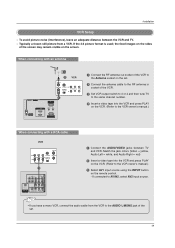
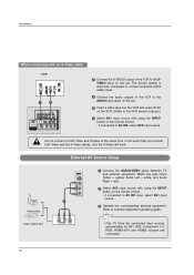
... & SERVICE) AUDIO IN REMOTE (RGB/DVI) CONTROL IN HDMI / DVI IN ANTENNA/ CABLE IN RS-232C IN When connecting with a (CONTROL&SERVICE) RCA cable 1 Connect the RF antenna out socket of the VCR to the Antenna socket on the VCR. (Refer to the VCR owner's manual.) VCR ANT IN OUT S-VIDEO (R) AUDIO (L) VIDEO OUTPUT SWITCH IN 34 VIDEO AUDIO ANT OUT 1 OPTICAL DIGITAL AUDIO ( ) VIDEOS-VIDEO VIDEOAUDIO AUDIO OUT 1 Connect the AUDIO/VIDEO jacks between the VCR and TV. - Typically a frozen still picture from the VCR to the AUDIO L/MONO jack of the set . 2 Connect the antenna cable...
... & SERVICE) AUDIO IN REMOTE (RGB/DVI) CONTROL IN HDMI / DVI IN ANTENNA/ CABLE IN RS-232C IN When connecting with a (CONTROL&SERVICE) RCA cable 1 Connect the RF antenna out socket of the VCR to the Antenna socket on the VCR. (Refer to the VCR owner's manual.) VCR ANT IN OUT S-VIDEO (R) AUDIO (L) VIDEO OUTPUT SWITCH IN 34 VIDEO AUDIO ANT OUT 1 OPTICAL DIGITAL AUDIO ( ) VIDEOS-VIDEO VIDEOAUDIO AUDIO OUT 1 Connect the AUDIO/VIDEO jacks between the VCR and TV. - Typically a frozen still picture from the VCR to the AUDIO L/MONO jack of the set . 2 Connect the antenna cable...
Owners Manual
Page 20
... Video Game Set 1 L AUDIO R VIDEO 1 Connect the AUDIO/VIDEO jacks between TV and external equipment. compared to normal composite (RCA cable) input. 2 Connect the audio outputs of the VCR to the SVIDEO input on the set . 3 Insert a video tape into the VCR and press PLAY on the VCR. (Refer to the VCR owner's manual.) 4 Select AV1 input source with using the INPUT button on the remote control. - The picture quality is improved; If connected to AV IN2, select AV2 input source. Installation COMPONENT IN AV OUT AV IN 1 VIDEO AUDIO OPTICAL DIGITAL AUDIO S-VIDEO VIDEO ( ) AUDIO...
... Video Game Set 1 L AUDIO R VIDEO 1 Connect the AUDIO/VIDEO jacks between TV and external equipment. compared to normal composite (RCA cable) input. 2 Connect the audio outputs of the VCR to the SVIDEO input on the set . 3 Insert a video tape into the VCR and press PLAY on the VCR. (Refer to the VCR owner's manual.) 4 Select AV1 input source with using the INPUT button on the remote control. - The picture quality is improved; If connected to AV IN2, select AV2 input source. Installation COMPONENT IN AV OUT AV IN 1 VIDEO AUDIO OPTICAL DIGITAL AUDIO S-VIDEO VIDEO ( ) AUDIO...
Owners Manual
Page 21
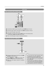
... 1 OPTICAL DIGITAL AUDIO OUT S-VIDEO VIDEO (MONO) AUDIO 1 Connect the S-VIDEO output of the DVD to the S-VIDEO input on the set. 2 Connect the audio outputs of the DVD to the DVD player's manual for operating instructions. If connected to AV IN2, select AV 2 input source. 5 Refer to the AUDIO input jacks on the set . 2 Select HDMI1/DVI or HDMI2 input source with using the INPUT button on the remote control. - When connecting with a HDMI cable ANTENNA/ CABLE IN HDMI IN 2 1(DVI) VIDEO AUDIO 1 COMPONENT IN HDMI-DVD OUTPUT DVD 1 Connect the HDMI output of the DVD to the HDMI IN...
... 1 OPTICAL DIGITAL AUDIO OUT S-VIDEO VIDEO (MONO) AUDIO 1 Connect the S-VIDEO output of the DVD to the S-VIDEO input on the set. 2 Connect the audio outputs of the DVD to the DVD player's manual for operating instructions. If connected to AV IN2, select AV 2 input source. 5 Refer to the AUDIO input jacks on the set . 2 Select HDMI1/DVI or HDMI2 input source with using the INPUT button on the remote control. - When connecting with a HDMI cable ANTENNA/ CABLE IN HDMI IN 2 1(DVI) VIDEO AUDIO 1 COMPONENT IN HDMI-DVD OUTPUT DVD 1 Connect the HDMI output of the DVD to the HDMI IN...
Owners Manual
Page 23
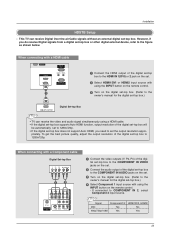
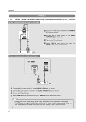
...set-top box. (Refer to the owner's manual for the digita(ClONTsROLe&StER-VtICoE) p box.) 4 Select Component 1 input source with a Component cable RS-232C IN (CONTROL & SERVICE) Digital Set-top Box B R (R) AUDIO (L) 1 2 VIDEO AUDIO 1 Connect the video outputs (Y, PB, PR) of the digiSERVICE tal set the output resolution appro- HDMI / DVI IN 3 Turn on the set -top box. priately. COMPONENT IN AV OUT AV IN 1 RGB IN (PC) REMORTEGBAIUNDIO IN CONTROL IN (RGB/DVI) RS-232C IN (CONTROL & SERVICE) OPTICAL DIGITAL AUDIO OUT S-VIDEO VIDEO (MONO) AUDIO SERVICE HDMI / DVI IN Signal...
...set-top box. (Refer to the owner's manual for the digita(ClONTsROLe&StER-VtICoE) p box.) 4 Select Component 1 input source with a Component cable RS-232C IN (CONTROL & SERVICE) Digital Set-top Box B R (R) AUDIO (L) 1 2 VIDEO AUDIO 1 Connect the video outputs (Y, PB, PR) of the digiSERVICE tal set the output resolution appro- HDMI / DVI IN 3 Turn on the set -top box. priately. COMPONENT IN AV OUT AV IN 1 RGB IN (PC) REMORTEGBAIUNDIO IN CONTROL IN (RGB/DVI) RS-232C IN (CONTROL & SERVICE) OPTICAL DIGITAL AUDIO OUT S-VIDEO VIDEO (MONO) AUDIO SERVICE HDMI / DVI IN Signal...
Owners Manual
Page 24
... digital set-top box supports Auto DVI function, the output resolution of the digital set . RGB IN 3 Turn on the digital set-top box. (Refer to the owner's manual for the d(PCi)gital set-top box.) REMORTEGBAIUNDIO IN CONTROL IN (RGB/DVI) 4 Select HDMI1/DVI input source with a HDMI to DVI cable SERVICE HDMI IN 2 1(DVI) 1 RGB IN (PC) AUDIO IN REMOTE (RGB/DVI) CONTROL IN RS-232C IN (CONTROL & SERVICE) 2 COMPONENT IN AV OUT AV IN 1 1(DVI) RS-232C IN (CONTROL & SERVICE) DVI-DTV OUTPUT (R) AUDIO (L) Digital Set-top Box 1 Connect the DVI output of the digital set-top box...
... digital set-top box supports Auto DVI function, the output resolution of the digital set . RGB IN 3 Turn on the digital set-top box. (Refer to the owner's manual for the d(PCi)gital set-top box.) REMORTEGBAIUNDIO IN CONTROL IN (RGB/DVI) 4 Select HDMI1/DVI input source with a HDMI to DVI cable SERVICE HDMI IN 2 1(DVI) 1 RGB IN (PC) AUDIO IN REMOTE (RGB/DVI) CONTROL IN RS-232C IN (CONTROL & SERVICE) 2 COMPONENT IN AV OUT AV IN 1 1(DVI) RS-232C IN (CONTROL & SERVICE) DVI-DTV OUTPUT (R) AUDIO (L) Digital Set-top Box 1 Connect the DVI output of the digital set-top box...
Owners Manual
Page 25
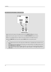
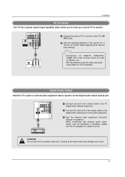
... Digital Audio Output Optical port. Digital Audio Output - Send the TV's audio to p.43) CAUTION Do not look into the optical output port. The TV has a special signal output capability which allows you to the digital audio optical input on the audio equipment. 3 See the external audio equipment instruction manual for VCR recording. COMPONENT IN AV OUT AV IN 1 VIDEO AUDIO OPTICAL DIGITAL AUDIO OUT S-VIDEO VIDEO (MONO) AUDIO 1 Connect the second TV or monitor to the TV's AV OUT jacks. 2 See the Operating Manual of the optical cable to hook...
... Digital Audio Output Optical port. Digital Audio Output - Send the TV's audio to p.43) CAUTION Do not look into the optical output port. The TV has a special signal output capability which allows you to the digital audio optical input on the audio equipment. 3 See the external audio equipment instruction manual for VCR recording. COMPONENT IN AV OUT AV IN 1 VIDEO AUDIO OPTICAL DIGITAL AUDIO OUT S-VIDEO VIDEO (MONO) AUDIO 1 Connect the second TV or monitor to the TV's AV OUT jacks. 2 See the Operating Manual of the optical cable to hook...
Owners Manual
Page 26
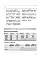
.... • If the PC does not support Auto DVI, you need to the AUDIO IN(RGB/DVI) jack on the set. 3 Turn on the remote control. To get the best picture quality, adjust the output resolution of the PC to set . 4 Select HDMI1/DVI input source with using the INPUT button on the PC and the set the output resolution appropriaRSt-2e32lCyIN. This TV provides Plug and Play capability, meaning that the PC adjusts automatically to 1024x768, 60Hz. (CONTROL&SERVICE) 26
.... • If the PC does not support Auto DVI, you need to the AUDIO IN(RGB/DVI) jack on the set. 3 Turn on the remote control. To get the best picture quality, adjust the output resolution of the PC to set . 4 Select HDMI1/DVI input source with using the INPUT button on the PC and the set the output resolution appropriaRSt-2e32lCyIN. This TV provides Plug and Play capability, meaning that the PC adjusts automatically to 1024x768, 60Hz. (CONTROL&SERVICE) 26
Owners Manual
Page 27
... of HDMI/DVI Source Devices or contact your service center. 5. When Source Devices connected with HDMI/DVI Input, output TV SET Resolution (480p, 720p, 1080i) and TV SET Display fit EIA/CEA-861-B Specification to the Manual of the PC graphic card can not be noise associated with HDMI/DVI Input, output PC Resolution (VGA, SVGA, XGA, WXGA), Position and Size may not work if a HDMI to DVI Cable is not supported TV SET output in use. 2. Avoid keeping a fixed image...
... of HDMI/DVI Source Devices or contact your service center. 5. When Source Devices connected with HDMI/DVI Input, output TV SET Resolution (480p, 720p, 1080i) and TV SET Display fit EIA/CEA-861-B Specification to the Manual of the PC graphic card can not be noise associated with HDMI/DVI Input, output PC Resolution (VGA, SVGA, XGA, WXGA), Position and Size may not work if a HDMI to DVI Cable is not supported TV SET output in use. 2. Avoid keeping a fixed image...

Owners Manual
Page 28
.... 1 Press the ADJUST button and then use D / E button to select Resolution, POSITION, SIZE, or PHASE. 2 Press ENTER button and then use F / G button to original factory values) 1 2 3 4 5 6 7 8 9 0 FLASHBK EZ PIC EZ SOUND SAP CC ADJUST ADJUST - Installation Screen Setup for screen Resolution, Position, Size, and Phase 4 5 6 7 8 9 0 FLASHBK EZ PIC EZ SOUND SAP CC ADJUST ADJUST Mini Glossary Position This function is to adjust picture to PC input and select HDMI/DVI input, this function is used . - When RGB connect to PC input and select the RGB-PC...
.... 1 Press the ADJUST button and then use D / E button to select Resolution, POSITION, SIZE, or PHASE. 2 Press ENTER button and then use F / G button to original factory values) 1 2 3 4 5 6 7 8 9 0 FLASHBK EZ PIC EZ SOUND SAP CC ADJUST ADJUST - Installation Screen Setup for screen Resolution, Position, Size, and Phase 4 5 6 7 8 9 0 FLASHBK EZ PIC EZ SOUND SAP CC ADJUST ADJUST Mini Glossary Position This function is to adjust picture to PC input and select HDMI/DVI input, this function is used . - When RGB connect to PC input and select the RGB-PC...
Owners Manual
Page 29
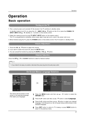
..., disconnect the power plug from the wall power outlet. First select your language. 1 Press the MENU button and then use D / E button to select the OPTION menu. 2 Press the G button and then use D / E button to select Language. 3 Press the G button and then use D / E button to switch the sound off, press the MUTE button. 3. This TV is programmed to remember which power state it was last set to adjust the volume. 2. Channel Selection Press the CH D / E or NUMBER buttons to select a channel number. • If...
..., disconnect the power plug from the wall power outlet. First select your language. 1 Press the MENU button and then use D / E button to select the OPTION menu. 2 Press the G button and then use D / E button to select Language. 3 Press the G button and then use D / E button to switch the sound off, press the MUTE button. 3. This TV is programmed to remember which power state it was last set to adjust the volume. 2. Channel Selection Press the CH D / E or NUMBER buttons to select a channel number. • If...

Owners Manual
Page 30
EZ Scan Manual Scan Channel Edit DTV Signal Input Source Input Label Set ID EZ Picture Color Temperature XD Advanced Video Reset Lock System Set Password Block Channel Movie Rating TV Rating-Children TV Rating-General Input Block Audio Language EZ Sound Balance TV Speaker Aspect Ratio Caption/Text Caption Option Language ISM Method Low Power Auto Clock Manual Clock Off Timer On Timer Sleep Timer Auto Off • Your TV's OSD (On Screen Display) may differ slightly from what is shown in this manual. 30...
EZ Scan Manual Scan Channel Edit DTV Signal Input Source Input Label Set ID EZ Picture Color Temperature XD Advanced Video Reset Lock System Set Password Block Channel Movie Rating TV Rating-Children TV Rating-General Input Block Audio Language EZ Sound Balance TV Speaker Aspect Ratio Caption/Text Caption Option Language ISM Method Low Power Auto Clock Manual Clock Off Timer On Timer Sleep Timer Auto Off • Your TV's OSD (On Screen Display) may differ slightly from what is shown in this manual. 30...
Owners Manual
Page 31
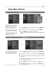
... Scan again after any Antenna/Cable connection changes. - D E TV G 2 TV 2-0 Press to stop the current scan and start DIGITAL ANTENNA channel scan. Setup Menu Options Operation EZ Scan (Channel Search) EZ Scan Manual Scan Channel Edit DTV Signal Input Source Input Label Set ID EZ Scan Manual Scan Channel Edit DTV Signal Input Source Input Label Set ID G Selection ( G or ) leads you want to add or delete. 5 Press the ENTER button to add or delete for ANTENNA, and CABLE. Automatically finds all channels available through antenna or cable inputs...
... Scan again after any Antenna/Cable connection changes. - D E TV G 2 TV 2-0 Press to stop the current scan and start DIGITAL ANTENNA channel scan. Setup Menu Options Operation EZ Scan (Channel Search) EZ Scan Manual Scan Channel Edit DTV Signal Input Source Input Label Set ID EZ Scan Manual Scan Channel Edit DTV Signal Input Source Input Label Set ID G Selection ( G or ) leads you want to add or delete. 5 Press the ENTER button to add or delete for ANTENNA, and CABLE. Automatically finds all channels available through antenna or cable inputs...
Owners Manual
Page 51
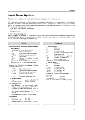
... the broadcasting station. Viewing can be blocked by the type of program and by broadcasting stations. Most television programs and television movies can be blocked. Set ratings and categories to be used to block program viewing based on the ratings sent by TV Rating and/or Individual Categories. Operation Lock Menu Options Parental Control can be blocked. 2. The default setting is to block specific channels, ratings and other viewing sources. For...
... the broadcasting station. Viewing can be blocked by the type of program and by broadcasting stations. Most television programs and television movies can be blocked. Set ratings and categories to be used to block program viewing based on the ratings sent by TV Rating and/or Individual Categories. Operation Lock Menu Options Parental Control can be blocked. 2. The default setting is to block specific channels, ratings and other viewing sources. For...

Owners Manual
Page 52
... MENU button to return to block specific channels, ratings, and external viewing sources. - You can view those programs. • TV Rating-General: Based on the ratings, blocks certain TV programs that you and your family do not want to block from the external source devices you have hooked up previously. • Set Password: Change the password by blocking out all the movies with the initial password "0-0-0-0". 2 Use the D / E button...
... MENU button to return to block specific channels, ratings, and external viewing sources. - You can view those programs. • TV Rating-General: Based on the ratings, blocks certain TV programs that you and your family do not want to block from the external source devices you have hooked up previously. • Set Password: Change the password by blocking out all the movies with the initial password "0-0-0-0". 2 Use the D / E button...
Owners Manual
Page 61
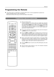
..., the button selected component will turn off on the remote control. Programming code numbers for the corresponding component can operate the component without programming, turn on the component such as a VCR and press the corresponding MODE button (VCR) on the remote control, while illuminating on the selected component. MENU BRIGHT + ENTER EXIT TIMER RATIO INFO VOL MUTE FAV CH 1 2 3 4 5 6 7 8 9 0 FLASHBK EZ PIC EZ SOUND SAP CC ADJUST 1 Test your remote control can be programmed to store the code. Reference Programming the Remote G The remote control is correct...
..., the button selected component will turn off on the remote control. Programming code numbers for the corresponding component can operate the component without programming, turn on the component such as a VCR and press the corresponding MODE button (VCR) on the remote control, while illuminating on the selected component. MENU BRIGHT + ENTER EXIT TIMER RATIO INFO VOL MUTE FAV CH 1 2 3 4 5 6 7 8 9 0 FLASHBK EZ PIC EZ SOUND SAP CC ADJUST 1 Test your remote control can be programmed to store the code. Reference Programming the Remote G The remote control is correct...
Owners Manual
Page 64
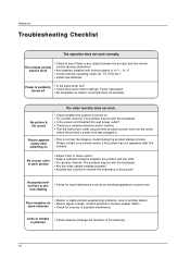
... broadcast. • Is the power cord inserted into the outlet where the product's power cord was plugged in. Horizontal/vertical bars or pic- The remote control doesn't work • Check to -)? • Correct remote operating mode set ? • Check the power control settings. Reference Troubleshooting Checklist The operation does not work . No or poor color or poor picture • Adjust Color in pictures • Check antenna (Change the direction of the picture. The problem may be with correct...
... broadcast. • Is the power cord inserted into the outlet where the product's power cord was plugged in. Horizontal/vertical bars or pic- The remote control doesn't work • Check to -)? • Correct remote operating mode set ? • Check the power control settings. Reference Troubleshooting Checklist The operation does not work . No or poor color or poor picture • Adjust Color in pictures • Check antenna (Change the direction of the picture. The problem may be with correct...

