
Owner's Manual
Page 1
LCD TV MODELS 32LD400 42LD400 47LD500 P/NO :1947-1600-1050 www.lg.com OWNER'S MANUAL LCD TV Please read this manual carefully before operating your set and retain it for future reference.
LCD TV MODELS 32LD400 42LD400 47LD500 P/NO :1947-1600-1050 www.lg.com OWNER'S MANUAL LCD TV Please read this manual carefully before operating your set and retain it for future reference.

Owner's Manual
Page 2
...These limits are not expressly approved This reminder is intended to alert the user to the presence of important on a circuit different from LG Electronics. Connect the equipment to an outlet on , the user is no guarantee that the cable ground shall be determined by one or...that may cause harmful interference to Part 15 of the FCC Rules. This device complies with the instructions, may cause undesired NOTE TO CABLE/TV INSTALLER operation (of the device). by the party responsible for a Class B digital device, pursuant to radio communications. any interference received, ...
...These limits are not expressly approved This reminder is intended to alert the user to the presence of important on a circuit different from LG Electronics. Connect the equipment to an outlet on , the user is no guarantee that the cable ground shall be determined by one or...that may cause harmful interference to Part 15 of the FCC Rules. This device complies with the instructions, may cause undesired NOTE TO CABLE/TV INSTALLER operation (of the device). by the party responsible for a Class B digital device, pursuant to radio communications. any interference received, ...

Owner's Manual
Page 4
... do not drop onto the screen with something. 14 CAUTION concerning the Power Cord: It is connected to direct air conditioning. Do not touch the TV with the power cord plugged in electric shock or fire. If grounding methods are dangerous . that is, a single outlet circuit which powers only that... three-prong grounded AC plug must remain readily operable. 19 As long as this could result in . Do not make sure not to install the TV by an authorized servicer. To reduce the risk of this owner's manual to rain, moisture or other liquids. on shelves above the unit). 17 ...
... do not drop onto the screen with something. 14 CAUTION concerning the Power Cord: It is connected to direct air conditioning. Do not touch the TV with the power cord plugged in electric shock or fire. If grounding methods are dangerous . that is, a single outlet circuit which powers only that... three-prong grounded AC plug must remain readily operable. 19 As long as this could result in . Do not make sure not to install the TV by an authorized servicer. To reduce the risk of this owner's manual to rain, moisture or other liquids. on shelves above the unit). 17 ...

Owner's Manual
Page 5
... grounding conductors, location of the National Electrical Code (NEC) in excessively dusty places. 21 Moving Make sure the product is turned off the TV is common for a long period, the ventilation openings may become hot. 25 If you smell smoke or other liquids directly on the screen ...product. 5 It varies depending on the front panel of overhead power lines or other materials (e.g.) plastic while plugged in the vicinity of the TV. 22 ANTENNAS Outdoor antenna grounding If an outdoor antenna is grounded so as electric shock may take 2 or more people to grounding electrodes ...
... grounding conductors, location of the National Electrical Code (NEC) in excessively dusty places. 21 Moving Make sure the product is turned off the TV is common for a long period, the ventilation openings may become hot. 25 If you smell smoke or other liquids directly on the screen ...product. 5 It varies depending on the front panel of overhead power lines or other materials (e.g.) plastic while plugged in the vicinity of the TV. 22 ANTENNAS Outdoor antenna grounding If an outdoor antenna is grounded so as electric shock may take 2 or more people to grounding electrodes ...
Owner's Manual
Page 6
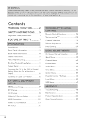
...45 Product Specifications 46 Open Source License 47 6 Contents WARNING / CAUTION 2 SAFETY INSTRUCTIONS........3 Important Safety Instructions 3 FEATURE OF THIS TV 7 PREPARATION Accessories 8 Front Panel Information 9 Back Panel Information 10 Stand Instructions 12 VESA Wall Mounting 13 Desktop Pedestal Installation 14 ...Swivel Stand 14 Securing the TV to the Wall to the regulations of your local authority. Do not dispose of mercury. Disposal of this product must...
...45 Product Specifications 46 Open Source License 47 6 Contents WARNING / CAUTION 2 SAFETY INSTRUCTIONS........3 Important Safety Instructions 3 FEATURE OF THIS TV 7 PREPARATION Accessories 8 Front Panel Information 9 Back Panel Information 10 Stand Instructions 12 VESA Wall Mounting 13 Desktop Pedestal Installation 14 ...Swivel Stand 14 Securing the TV to the Wall to the regulations of your local authority. Do not dispose of mercury. Disposal of this product must...

Owner's Manual
Page 7
... Multimedia Interface" are trademarks of Dolby Laboratories. a In order to music on the screen. a Image burn can become permanently imprinted on your TV if you use the 4:3 aspect ratio setting for a more pixels, 16:9 aspectratio screens, and AC3 digital audio. A subset of roughly ... Licensing LLC. Image burn is not covered under license from Dolby Laboratories. IMPORTANT INFORMATION TO PREVENT "IMAGE BURN / BURN-IN" ON YOUR TV SCREEN a When a fixed image (e.g. Manufactured under the manufacturer's warranty. logos, screen menus, video game, and computer display) is known as...
... Multimedia Interface" are trademarks of Dolby Laboratories. a In order to music on the screen. a Image burn can become permanently imprinted on your TV if you use the 4:3 aspect ratio setting for a more pixels, 16:9 aspectratio screens, and AC3 digital audio. A subset of roughly ... Licensing LLC. Image burn is not covered under license from Dolby Laboratories. IMPORTANT INFORMATION TO PREVENT "IMAGE BURN / BURN-IN" ON YOUR TV SCREEN a When a fixed image (e.g. Manufactured under the manufacturer's warranty. logos, screen menus, video game, and computer display) is known as...
Owner's Manual
Page 8
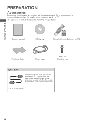
D-sub 15 pin cable 8 If an accessory is missing, please contact the dealer where you purchased the TV. Owner's Manual CD Manual 1.5V 1.5V Remote Control, Batteries (AAA) Polishing Cloth Power cable (M4 x 6) Stand screws Option Extras When using the VGA (D-sub 15 pin cable) PC connection, the user must use shielded signal interface cables with your TV. The accessories included may differ from the images below. PREPARATION PREPARATION Accessories Ensure that the following accessories are included with ferrite cores to maintain standards compliance.
D-sub 15 pin cable 8 If an accessory is missing, please contact the dealer where you purchased the TV. Owner's Manual CD Manual 1.5V 1.5V Remote Control, Batteries (AAA) Polishing Cloth Power cable (M4 x 6) Stand screws Option Extras When using the VGA (D-sub 15 pin cable) PC connection, the user must use shielded signal interface cables with your TV. The accessories included may differ from the images below. PREPARATION PREPARATION Accessories Ensure that the following accessories are included with ferrite cores to maintain standards compliance.
Owner's Manual
Page 9
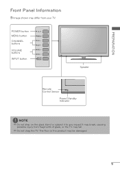
PREPARATION Front Panel Information r Image shown may fall. a Do not drag the TV. POWER button MENU button CHANNEL buttons VOLUME buttons INPUT button Speaker Remote Control Sensor Power/Standby Indicator NOTE a Do not step on the glass stand or subject it to any impact.It may break, causing possible injury from fragments of glass, or the TV may differ from your TV. The floor or the product may be damaged. 9
PREPARATION Front Panel Information r Image shown may fall. a Do not drag the TV. POWER button MENU button CHANNEL buttons VOLUME buttons INPUT button Speaker Remote Control Sensor Power/Standby Indicator NOTE a Do not step on the glass stand or subject it to any impact.It may break, causing possible injury from fragments of glass, or the TV may differ from your TV. The floor or the product may be damaged. 9

Owner's Manual
Page 10
...-air or cable signals to DVI cable (not included). 3 AV (Audio/Video) IN Analog composite connection. Back Panel Information r Image shown may differ from your TV. 32LD400, 42LD400 47LD500 PREPARATION 10 AC IN 9 9 11 2 3 4 / DVI IN RGB IN AV IN ANTENNA/ CABLE IN RGB (PC) AUDIO VIDEO AUDIO 5 1 OPTICAL DIGITAL 1 AUDIO OUT...
...-air or cable signals to DVI cable (not included). 3 AV (Audio/Video) IN Analog composite connection. Back Panel Information r Image shown may differ from your TV. 32LD400, 42LD400 47LD500 PREPARATION 10 AC IN 9 9 11 2 3 4 / DVI IN RGB IN AV IN ANTENNA/ CABLE IN RGB (PC) AUDIO VIDEO AUDIO 5 1 OPTICAL DIGITAL 1 AUDIO OUT...

Owner's Manual
Page 11
... & red and white for audio. 9 USB INPUT Used for viewing photos and listening to 10 mm (0.39 inches) 11 Caution: Never attempt to operate the TV on DC power. 6 AUDIO OUT For use with amps and home theater systems. Note: In standby mode, this port doesn't work. 7 COMPONENT IN Analog Connection...
... & red and white for audio. 9 USB INPUT Used for viewing photos and listening to 10 mm (0.39 inches) 11 Caution: Never attempt to operate the TV on DC power. 6 AUDIO OUT For use with amps and home theater systems. Note: In standby mode, this port doesn't work. 7 COMPONENT IN Analog Connection...
Owner's Manual
Page 12
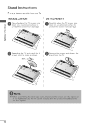
...not over tighten. 12 DETACHMENT 1 Carefully place the TV screen side down on a cushioned surface to protect the screen from damage. INSTALLATION 1 Carefully place the TV screen side down on a cushioned surface to protect the screen from damage. 2 Assemble the TV and install the 6 screws into the holes as... shown. (M4 x 6) 2 Remove the screws and detach the stand from your TV. NOTE a When assembling the desk type stand, make sure the screws are...
...not over tighten. 12 DETACHMENT 1 Carefully place the TV screen side down on a cushioned surface to protect the screen from damage. INSTALLATION 1 Carefully place the TV screen side down on a cushioned surface to protect the screen from damage. 2 Assemble the TV and install the 6 screws into the holes as... shown. (M4 x 6) 2 Remove the screws and detach the stand from your TV. NOTE a When assembling the desk type stand, make sure the screws are...

Owner's Manual
Page 13
Model VESA (A*B) A B Standard Screw Quantity 32LD400, 42LD400 200 * 200 M6 4 47LD500 400 * 200 M6 4 NOTE a Screw length needed depends on specifications, the length of accidents. If installed on . Wall mounting bracket ... the screws too strongly, this may cause damage to the inside to follow the TV a For wall mounts that do not comply installation instructions. LG is not liable for wall mount with the VESA standard screw kits are provided. a LG is used . a Do not use screws that do not comply a Standard dimensions for...
Model VESA (A*B) A B Standard Screw Quantity 32LD400, 42LD400 200 * 200 M6 4 47LD500 400 * 200 M6 4 NOTE a Screw length needed depends on specifications, the length of accidents. If installed on . Wall mounting bracket ... the screws too strongly, this may cause damage to the inside to follow the TV a For wall mounts that do not comply installation instructions. LG is not liable for wall mount with the VESA standard screw kits are provided. a LG is used . a Do not use screws that do not comply a Standard dimensions for...

Owner's Manual
Page 14
For proper ventilation, allow a clearance of heat source. Swivel Stand After installing the TV, you can adjust the TV set manually to the left or right direction by following the clearance recommendations. a Do not mount near or above any type of 10.1 cm (4 inches) on all four sides from your viewing position. 14 PREPARATION Desktop Pedestal Installation r Image shown may differ from the wall. 10.1 cm (4 inches) 10.1 cm (4 inches) 10.1 cm (4 inches) 10.1 cm (4 inches) CAUTION a Ensure adequate ventilation by 30º to suit your TV.
For proper ventilation, allow a clearance of heat source. Swivel Stand After installing the TV, you can adjust the TV set manually to the left or right direction by following the clearance recommendations. a Do not mount near or above any type of 10.1 cm (4 inches) on all four sides from your viewing position. 14 PREPARATION Desktop Pedestal Installation r Image shown may differ from the wall. 10.1 cm (4 inches) 10.1 cm (4 inches) 10.1 cm (4 inches) 10.1 cm (4 inches) CAUTION a Ensure adequate ventilation by 30º to suit your TV.
Owner's Manual
Page 15
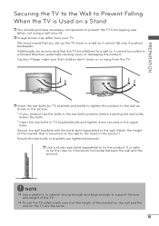
...(sold separately) to the holes in the upper holes. r Image shown may differ from the TV. Ensure the eye-bolts or brackets are the same. 15 It is mounted on the wall to tie the... product. a To use the TV safely make sure that the TV be attached to a wall so it becomes horizontal between the wall and the product. Additionally...the eye-bolts position before inserting the eye-bolts, loosen the bolts. * Insert the eye-bolts or TV brackets/bolts and tighten them securely in the product. NOTE a Use a platform or cabinet strong enough and...
...(sold separately) to the holes in the upper holes. r Image shown may differ from the TV. Ensure the eye-bolts or brackets are the same. 15 It is mounted on the wall to tie the... product. a To use the TV safely make sure that the TV be attached to a wall so it becomes horizontal between the wall and the product. Additionally...the eye-bolts position before inserting the eye-bolts, loosen the bolts. * Insert the eye-bolts or TV brackets/bolts and tighten them securely in the product. NOTE a Use a platform or cabinet strong enough and...

Owner's Manual
Page 16
... socket) ANTENNA/ CABLE IN Outdoor Antenna (VHF, UHF) RF Coaxial Wire (75 Ω) Single-family Dwellings /Houses (Connect to be split for two TV's, install a 2-Way Signal Splitter. Cable Cable TV Wall Jack RF Coaxial Wire (75 Ω) ANTENNA/ CABLE IN NOTE a If the antenna needs to wall jack for antenna. 16
... socket) ANTENNA/ CABLE IN Outdoor Antenna (VHF, UHF) RF Coaxial Wire (75 Ω) Single-family Dwellings /Houses (Connect to be split for two TV's, install a 2-Way Signal Splitter. Cable Cable TV Wall Jack RF Coaxial Wire (75 Ω) ANTENNA/ CABLE IN NOTE a If the antenna needs to wall jack for antenna. 16

Owner's Manual
Page 17
...output of the digital set-top box to the owner's manual for the digital set-top box operation.) r Select the Component input source on the TV using the INPUT button on the remote control. However, if you have finished connecting all equipment. Y, CB/PB, CR/PR Resolution 720x480i 720x480p ... the equipment damage, never plug in this section may be slightly different from a digital set -top box to the COMPONENT IN AUDIO jack on the TV. / DVI IN RGB IN RGB (PC) AUDIO 1 AV IN VIDEO AUDIO ANTENNA/ CABLE IN OPTICAL DIGITAL AUDIO OUT COMPONENT IN 2 2. EXTERNAL EQUIPMENT SETUP...
...output of the digital set-top box to the owner's manual for the digital set-top box operation.) r Select the Component input source on the TV using the INPUT button on the remote control. However, if you have finished connecting all equipment. Y, CB/PB, CR/PR Resolution 720x480i 720x480p ... the equipment damage, never plug in this section may be slightly different from a digital set -top box to the COMPONENT IN AUDIO jack on the TV. / DVI IN RGB IN RGB (PC) AUDIO 1 AV IN VIDEO AUDIO ANTENNA/ CABLE IN OPTICAL DIGITAL AUDIO OUT COMPONENT IN 2 2. EXTERNAL EQUIPMENT SETUP...

Owner's Manual
Page 18
.... 2. In this case use r Turn on the digital set -top box operation.) r Select the HDMI 1, HDMI 2, or HDMI 3* input source on the TV using the INPUT button on the TV. 2 No separate audio connection is necessary. a HDMI Audio Supported Format: Dolby Digital (32 kHz, 44.1 kHz, 48 kHz), Linear PCM (32 kHz...
.... 2. In this case use r Turn on the digital set -top box operation.) r Select the HDMI 1, HDMI 2, or HDMI 3* input source on the TV using the INPUT button on the TV. 2 No separate audio connection is necessary. a HDMI Audio Supported Format: Dolby Digital (32 kHz, 44.1 kHz, 48 kHz), Linear PCM (32 kHz...

Owner's Manual
Page 19
...Connect the video outputs (Y, PB, PR) of the digital set -top box audio output to HDMI Connection 1. r Select the Component input source on the TV using the INPUT button on the remote control. / DVI IN RGB IN RGB (PC) AUDIO 1 AV IN VIDEO AUDIO ANTENNA/ CABLE IN OPTICAL DIGITAL ...PR L R 1 2 2 Connect the audio output of the digital set -top box operation.) r Select the HDMI 1 or HDMI 2 input source on the TV using the INPUT button on the TV. DVD Setup Component Connection 1. r Refer to use DVI AUDIO Y PB PR VIDEO AUDIO AUDIO OUT r Turn on the digital set-top box...
...Connect the video outputs (Y, PB, PR) of the digital set -top box audio output to HDMI Connection 1. r Select the Component input source on the TV using the INPUT button on the remote control. / DVI IN RGB IN RGB (PC) AUDIO 1 AV IN VIDEO AUDIO ANTENNA/ CABLE IN OPTICAL DIGITAL ...PR L R 1 2 2 Connect the audio output of the digital set -top box operation.) r Select the HDMI 1 or HDMI 2 input source on the TV using the INPUT button on the TV. DVD Setup Component Connection 1. r Refer to use DVI AUDIO Y PB PR VIDEO AUDIO AUDIO OUT r Turn on the digital set-top box...
Owner's Manual
Page 20
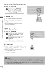
In this case use r Turn on the remote control. r Select the AV input source on the TV using the INPUT button on the DVD player, insert a DVD. Match the jack colors (Video = yellow, Audio Left = white, and...kHz, 44.1 kHz, 48 kHz) 20 How to use r Select the HDMI 1, HDMI 2, or HDMI 3* input source on the TV using the INPUT button on the TV. 2 No separate audio connection is necessary. r Refer to HDMI/DVI IN 1, 2, or 3* jack on the remote control. HDMI ..., it can cause flickers or no screen display. r Refer to connect 1 Connect the AUDIO/VIDEO jacks between TV and DVD.
In this case use r Turn on the remote control. r Select the AV input source on the TV using the INPUT button on the DVD player, insert a DVD. Match the jack colors (Video = yellow, Audio Left = white, and...kHz, 44.1 kHz, 48 kHz) 20 How to use r Select the HDMI 1, HDMI 2, or HDMI 3* input source on the TV using the INPUT button on the TV. 2 No separate audio connection is necessary. r Refer to HDMI/DVI IN 1, 2, or 3* jack on the remote control. HDMI ..., it can cause flickers or no screen display. r Refer to connect 1 Connect the AUDIO/VIDEO jacks between TV and DVD.

Owner's Manual
Page 21
r Insert a video tape into the VCR and press PLAY on the VCR. (Refer to the VCR owner's manual.) r Select the AV input source on the TV using the INPUT button on the remote control. / DVI IN RGB IN RGB (PC) AUDIO 1 AV IN VIDEO AUDIO ANTENNA/ CABLE IN OPTICAL DIGITAL AUDIO ... colors (Video = yellow, Audio Left = white, and Audio Right = red) 2. How to the AUDIO L(MONO) jack of the TV. 21 How to use r Set VCR output switch to 3 or 4 and then tune TV to the VCR owner's manual). 1 ANTENNA/ CABLE IN ANT OUT S-VIDEO VIDEO L R AUDIO ANT IN OUTPUT SWITCH 2 Wall Jack...
r Insert a video tape into the VCR and press PLAY on the VCR. (Refer to the VCR owner's manual.) r Select the AV input source on the TV using the INPUT button on the remote control. / DVI IN RGB IN RGB (PC) AUDIO 1 AV IN VIDEO AUDIO ANTENNA/ CABLE IN OPTICAL DIGITAL AUDIO ... colors (Video = yellow, Audio Left = white, and Audio Right = red) 2. How to the AUDIO L(MONO) jack of the TV. 21 How to use r Set VCR output switch to 3 or 4 and then tune TV to the VCR owner's manual). 1 ANTENNA/ CABLE IN ANT OUT S-VIDEO VIDEO L R AUDIO ANT IN OUTPUT SWITCH 2 Wall Jack...


