

User Manual
Page 2
... shock hazard by inadvertent connection to the earth terminal of a three-pin plug. NO USER-SERVICEABLE PARTS INSIDE. If your dealer. Accessories FM indoor antenna (1) AM loop antenna (1) Loop antenna stand (1) GRC-700 (1) Batteries (R06/AA) (6) ENTER CONFIRM UP ME VOLU DOWN so mu mo e dit vie sic und mode eep Sl listen CONTRAST ON/STANDBY Backlight Keep this page carefully...
... shock hazard by inadvertent connection to the earth terminal of a three-pin plug. NO USER-SERVICEABLE PARTS INSIDE. If your dealer. Accessories FM indoor antenna (1) AM loop antenna (1) Loop antenna stand (1) GRC-700 (1) Batteries (R06/AA) (6) ENTER CONFIRM UP ME VOLU DOWN so mu mo e dit vie sic und mode eep Sl listen CONTRAST ON/STANDBY Backlight Keep this page carefully...
User Manual
Page 3
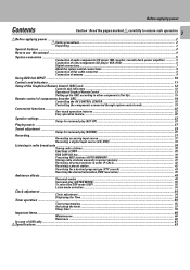
... the components connected through system control cords 19 Convenient functions ...22 One-touch operation features ...22 Easy operation feature ...22 Speaker settings ...23 Setup for surround play (SET UP) ...23 Playing music ...27 Sound adjustment ...29 Setup for a desired program type (PTY search 43 Reserving the desired information (EON reservation 45 Ambience effects ...48 Surround modes ...48 Surround play (SOUND) ...29 Recording ...31 Recording an analog input source ...31 Recording a digital input source (CD, DVD 33 Listening to radio broadcasts ...38 Tuning radio stations...38...
... the components connected through system control cords 19 Convenient functions ...22 One-touch operation features ...22 Easy operation feature ...22 Speaker settings ...23 Setup for surround play (SET UP) ...23 Playing music ...27 Sound adjustment ...29 Setup for a desired program type (PTY search 43 Reserving the desired information (EON reservation 45 Ambience effects ...48 Surround modes ...48 Surround play (SOUND) ...29 Recording ...31 Recording an analog input source ...31 Recording a digital input source (CD, DVD 33 Listening to radio broadcasts ...38 Tuning radio stations...38...

User Manual
Page 4
... output. Audio CD) using your multi speakers. used Step No. The 3 STEREO mode will redirect the surround signal to steer the Left, Center, Right and Surround channel audio signals. The LCD also shows information on and starts playback. BefoSryesatepmplcyionngnpeocwtioenr 4 Special features True home theater sound DTS DTS (Digital Theater Systems) is a 5.1 channel digital audio format that you connect the digital output of the player to the digital input of this unit. The PRO LOGIC mode uses the built-in this AV CONTROL CENTER...
... output. Audio CD) using your multi speakers. used Step No. The 3 STEREO mode will redirect the surround signal to steer the Left, Center, Right and Surround channel audio signals. The LCD also shows information on and starts playback. BefoSryesatepmplcyionngnpeocwtioenr 4 Special features True home theater sound DTS DTS (Digital Theater Systems) is a 5.1 channel digital audio format that you connect the digital output of the player to the digital input of this unit. The PRO LOGIC mode uses the built-in this AV CONTROL CENTER...
User Manual
Page 5
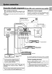
....INPUT FRONT SURROUND CENTER PLAY PLAY REC PLAY REC PLAY SUB WOOFER Connection cable PLAY OUT REC IN REC PLAY IN OUT LINE OUTPUT Remove cap Shape of AC outlet Australia x 1 UNSWITCHED To wall AC outlet *2 Cassette deck 2 MD recorder or Cassette deck 1 System control cord *1 Power amplifier M-A300 *1 For the connection and operation procedures of the power amplifier and speakers, refer to adhere followings. CD player The connected components shown here are completed. Also connect the system control cords when the KENWOOD Audio Component System "SERIES...
....INPUT FRONT SURROUND CENTER PLAY PLAY REC PLAY REC PLAY SUB WOOFER Connection cable PLAY OUT REC IN REC PLAY IN OUT LINE OUTPUT Remove cap Shape of AC outlet Australia x 1 UNSWITCHED To wall AC outlet *2 Cassette deck 2 MD recorder or Cassette deck 1 System control cord *1 Power amplifier M-A300 *1 For the connection and operation procedures of the power amplifier and speakers, refer to adhere followings. CD player The connected components shown here are completed. Also connect the system control cords when the KENWOOD Audio Component System "SERIES...

User Manual
Page 6
...DVD players. When using DVD 6ch INPUT. 0 ANTENNA AM VIDEO CD (OPTICAL 1) DVD (COAXAL) FM 75Ω GND PRE OUT FRONT SURROUND CENTER L CONNECT WITH POWER AMPLIFIER R SUB WOOFER REC PLAY VIDEO 1 REC PLAY PLAY DVD/ MONITOR 6CH.INPUT OUT VIDEO 2 CD MD/TAPE1 DIGITAL IN TAPE 2/MON SYSTEM CONTROL DVD/6CH.INPUT FRONT SURROUND CENTER PLAY PLAY REC PLAY REC PLAY SUB WOOFER UNSWITCHED Audio IN Audio OUT Video IN VCR Video OUT *2 Audio CENTER OUT Audio SUBWOOFER OUT Audio SURROUND OUT Audio FRONT OUT Audio DIGITAL OUT Video OUT DVD The connected components are connected...
...DVD players. When using DVD 6ch INPUT. 0 ANTENNA AM VIDEO CD (OPTICAL 1) DVD (COAXAL) FM 75Ω GND PRE OUT FRONT SURROUND CENTER L CONNECT WITH POWER AMPLIFIER R SUB WOOFER REC PLAY VIDEO 1 REC PLAY PLAY DVD/ MONITOR 6CH.INPUT OUT VIDEO 2 CD MD/TAPE1 DIGITAL IN TAPE 2/MON SYSTEM CONTROL DVD/6CH.INPUT FRONT SURROUND CENTER PLAY PLAY REC PLAY REC PLAY SUB WOOFER UNSWITCHED Audio IN Audio OUT Video IN VCR Video OUT *2 Audio CENTER OUT Audio SUBWOOFER OUT Audio SURROUND OUT Audio FRONT OUT Audio DIGITAL OUT Video OUT DVD The connected components are connected...

User Manual
Page 8
.... AV CONTROL CENTER Connection example ANTENNA AM FM 75Ω GND L CONNECT WITH POWER AMPLIFIER R POWER AMPLIFIER SYSTEM CONTROL System control cord UNSWITCHED GRAPHIC EQUALIZER MD recorder SYSTEM CONTROL SYSTEM CONTROL System control cord The SERIES 21 components which is connected to KENWOOD audio component system "SERIES 21", also connect them through system control cords) Remote Control * Lets you start of playback when recording from a source component, the input selector on the socket at the rear of sound or noise produced. 2. System connection 8 About...
.... AV CONTROL CENTER Connection example ANTENNA AM FM 75Ω GND L CONNECT WITH POWER AMPLIFIER R POWER AMPLIFIER SYSTEM CONTROL System control cord UNSWITCHED GRAPHIC EQUALIZER MD recorder SYSTEM CONTROL SYSTEM CONTROL System control cord The SERIES 21 components which is connected to KENWOOD audio component system "SERIES 21", also connect them through system control cords) Remote Control * Lets you start of playback when recording from a source component, the input selector on the socket at the rear of sound or noise produced. 2. System connection 8 About...

User Manual
Page 11
...7 INPUT MODE key * Use to switch between ON and STANDBY. 2 Remote sensor 3 TIMER SET key Press to select the Dolby digital mode. 9 DTS key 0 CIRCLE SURROUND key ! This condition is flowing into the unit's internal circuitry to select the listening mode. indicator Display SLEEP indicator 1 2 3 4 5 6 7 8 9 0! @ # ON/STANDBY PHONES INPUT TAPE 2 / MONITOR TIMER SET DIGITAL REC MODE SET UP SOUND INPUT MODE TIMER MODE CLOCK DISPLAY RDS PTY TA/NEWS DIGITAL DTS CIRCLE LISTEN SURROUND MODE MULTI.CONTROL LEVEL A.MEMO AUTO BAND PTY SELECT TUNING VOLUME CONTROL OPEN...
...7 INPUT MODE key * Use to switch between ON and STANDBY. 2 Remote sensor 3 TIMER SET key Press to select the Dolby digital mode. 9 DTS key 0 CIRCLE SURROUND key ! This condition is flowing into the unit's internal circuitry to select the listening mode. indicator Display SLEEP indicator 1 2 3 4 5 6 7 8 9 0! @ # ON/STANDBY PHONES INPUT TAPE 2 / MONITOR TIMER SET DIGITAL REC MODE SET UP SOUND INPUT MODE TIMER MODE CLOCK DISPLAY RDS PTY TA/NEWS DIGITAL DTS CIRCLE LISTEN SURROUND MODE MULTI.CONTROL LEVEL A.MEMO AUTO BAND PTY SELECT TUNING VOLUME CONTROL OPEN...
User Manual
Page 12
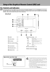
... button $ 3 Mute button • 4 Volume up/down button ¶ 5 Contrast button $ 6 On/Standby button ¶ 7 Backlight button $ 8 Quick Access menu * edit movie music sound listen mode sleep : Editing feature : Movie device controls such as DVD players or VCRs. : Music device controls such as CD players or the radio tuner. : Sound controls, such as "midnight" mode. : Listen modes such as stereo, Dolby Digital. : Sleep timer 9 Touch screen display # 0 Stylus (stored on top edge) # Approximate operating range Infrared remote control Remote sensor 6m GRC Infrared ray system...
... button $ 3 Mute button • 4 Volume up/down button ¶ 5 Contrast button $ 6 On/Standby button ¶ 7 Backlight button $ 8 Quick Access menu * edit movie music sound listen mode sleep : Editing feature : Movie device controls such as DVD players or VCRs. : Music device controls such as CD players or the radio tuner. : Sound controls, such as "midnight" mode. : Listen modes such as stereo, Dolby Digital. : Sleep timer 9 Touch screen display # 0 Stylus (stored on top edge) # Approximate operating range Infrared remote control Remote sensor 6m GRC Infrared ray system...
User Manual
Page 15
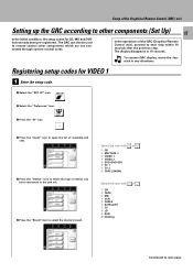
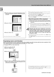
... with 1 CD 2 TAPE 3 MD 4 VCR 5 CABLE 6 SATELLITE 7 TV 8 LD 9 DVD 0 Nothing or . or . In the operations of device you have already been pre-registered. Setup of the Graphical Remote Control (GRC) unit Setting up the GRC according to other components which are not connected through system control cords. Registering setup codes for CD, MD and DVD have connected to the jack set. 6 Press the "Brand" icon to select the device's brand. The display disappears...
... with 1 CD 2 TAPE 3 MD 4 VCR 5 CABLE 6 SATELLITE 7 TV 8 LD 9 DVD 0 Nothing or . or . In the operations of device you have already been pre-registered. Setup of the Graphical Remote Control (GRC) unit Setting up the GRC according to other components which are not connected through system control cords. Registering setup codes for CD, MD and DVD have connected to the jack set. 6 Press the "Brand" icon to select the device's brand. The display disappears...
User Manual
Page 16
... "Code" icon. do not move GRC or the device's remote until GRC displays the the Function change menu again. ÷ Be sure to next page GRC will not learn . 10 cm ÷ This may not automatically display the "System" screen. ÷ With CD-Carrousel, select "Sys-carrousel". ÷ When CD, MD and TAPE are connected through system control cords, select "System". Set up other universal remotes. This instructs GRC to send a "Power...
... "Code" icon. do not move GRC or the device's remote until GRC displays the the Function change menu again. ÷ Be sure to next page GRC will not learn . 10 cm ÷ This may not automatically display the "System" screen. ÷ With CD-Carrousel, select "Sys-carrousel". ÷ When CD, MD and TAPE are connected through system control cords, select "System". Set up other universal remotes. This instructs GRC to send a "Power...
User Manual
Page 18
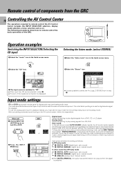
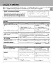
...the Quick access menu. Input mode settings CD and DVD inputs each connected component. Analog input: Select this setting to play analog signals from a DVD, CD, or LD player. However, even when this setting to play mode 1 DIGITAL AUTO (digital input, auto sound) 2 DIGITAL MANUAL (digital input, manual sound) 3 ANALOG (analog input, manual sound) ÷ With DIGITAL MANUAL, the audio may be not output when the signal is to select CD or DVD. The following procedures show how to remote control the basic operations of input signal (Dolby Digital, PCM, DTS ) and the speaker setting...
...the Quick access menu. Input mode settings CD and DVD inputs each connected component. Analog input: Select this setting to play analog signals from a DVD, CD, or LD player. However, even when this setting to play mode 1 DIGITAL AUTO (digital input, auto sound) 2 DIGITAL MANUAL (digital input, manual sound) 3 ANALOG (analog input, manual sound) ÷ With DIGITAL MANUAL, the audio may be not output when the signal is to select CD or DVD. The following procedures show how to remote control the basic operations of input signal (Dolby Digital, PCM, DTS ) and the speaker setting...
User Manual
Page 19
... ÷ System control connection 8 ÷ Setup of source components% CONFIRM UP ME VOLU DOWN CONTRAST ON/STANDBY BACKLIGHT Select the "music" icon in the fixed segment screen. (Select the icon) musi 2 Select the "CD" icon. Operating the CD player 1 Select the "music" icon in the Quick access menu. c 2 Select the "TUNER" icon Display the tuner operation menu. 3 Select the icon to be selected. ÷ For the operation of the CD player, also read the instruction manual of...
... ÷ System control connection 8 ÷ Setup of source components% CONFIRM UP ME VOLU DOWN CONTRAST ON/STANDBY BACKLIGHT Select the "music" icon in the fixed segment screen. (Select the icon) musi 2 Select the "CD" icon. Operating the CD player 1 Select the "music" icon in the Quick access menu. c 2 Select the "TUNER" icon Display the tuner operation menu. 3 Select the icon to be selected. ÷ For the operation of the CD player, also read the instruction manual of...

User Manual
Page 22
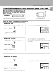
... AV CONTROL CENTER to put it to standby mode. ÷ The STANDBY indicator lights in standby mode, the operations as described below are possible provided that the associated components are connected through system control cords. Function available with the play key operation 1 Press the play . ÷ CD player and cassette deck. ÷ Turn on the system before switching the input selector. ÷ Select the source component with the input selector. 2 The selected source component starts to play key. 2 The system is switched...
... AV CONTROL CENTER to put it to standby mode. ÷ The STANDBY indicator lights in standby mode, the operations as described below are possible provided that the associated components are connected through system control cords. Function available with the play key operation 1 Press the play . ÷ CD player and cassette deck. ÷ Turn on the system before switching the input selector. ÷ Select the source component with the input selector. 2 The selected source component starts to play key. 2 The system is switched...
User Manual
Page 23
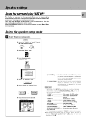
... speaker system and listening room environment in use. "SUBW Sub-woofer ON/OFF setting. "CNTR Center speaker setting. "REMIX"*1 Sub-woofer remix ON/OFF setting. SURROUND DISTANCE ........ When the SERIES 21 speakers are not necessary. Each press MULTI CONTROL LEVEL or key switches the indication. End of SET UP *1, *2 This setting is not available if "SW Off" is switched to each speaker. Main unit Each press of the SETUP key switches the adjustment...
... speaker system and listening room environment in use. "SUBW Sub-woofer ON/OFF setting. "CNTR Center speaker setting. "REMIX"*1 Sub-woofer remix ON/OFF setting. SURROUND DISTANCE ........ When the SERIES 21 speakers are not necessary. Each press MULTI CONTROL LEVEL or key switches the indication. End of SET UP *1, *2 This setting is not available if "SW Off" is switched to each speaker. Main unit Each press of the SETUP key switches the adjustment...
User Manual
Page 26
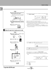
... of all the system's speakers (except the subwoofer) play at the same volume. 5 Press the "Test Tone" icon. (Select the icon) 5 Adjust the input level. (analog sources only) GRC 1 Select the "music" or "movie" icon in memory on a per-selector basis. "Speaker settings" £ C c h + 1 ) d B AUTO SOUND FM DTS DOLBY AM PRO LOGIC S MW MHz SLEEP LW KHz TIMER 1 2 Display when test tone is output from a surround speaker ÷ Be...
... of all the system's speakers (except the subwoofer) play at the same volume. 5 Press the "Test Tone" icon. (Select the icon) 5 Adjust the input level. (analog sources only) GRC 1 Select the "music" or "movie" icon in memory on a per-selector basis. "Speaker settings" £ C c h + 1 ) d B AUTO SOUND FM DTS DOLBY AM PRO LOGIC S MW MHz SLEEP LW KHz TIMER 1 2 Display when test tone is output from a surround speaker ÷ Be...
User Manual
Page 27
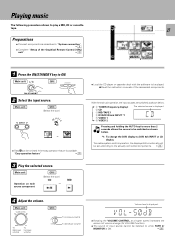
... each source component GRC (Select the icon) CD MD or ÷ Load the CD player or cassette deck with the software to be switched as shown below . *1: To change (AI VOLUME function). ÷ The sound of volume change the DVD display to DVD 6ch INPUT or LD display To enable system-control operation, the displayed information should be listened to the actually connected components. 0 4 Adjust the volume. Playing music The following procedure allows to ON. C D AUTO STEREO MEMO.TUNED...
... each source component GRC (Select the icon) CD MD or ÷ Load the CD player or cassette deck with the software to be switched as shown below . *1: To change (AI VOLUME function). ÷ The sound of volume change the DVD display to DVD 6ch INPUT or LD display To enable system-control operation, the displayed information should be listened to the actually connected components. 0 4 Adjust the volume. Playing music The following procedure allows to ON. C D AUTO STEREO MEMO.TUNED...

User Manual
Page 28
... PHONES jack. ÷ If headphones are not available. ÷ The speaker setting is not available with DVD 6ch INPUT. ÷ The sound adjustment is selected, all the speaker levels become 0 dB so the levels should be set on the source component. The Listen mode operations are plugged in during surround play , only the front L ch and R ch will be activated by pressing the TAPE 2/MONITOR key. 2. Refer to the STEREO mode...
... PHONES jack. ÷ If headphones are not available. ÷ The speaker setting is not available with DVD 6ch INPUT. ÷ The sound adjustment is selected, all the speaker levels become 0 dB so the levels should be set on the source component. The Listen mode operations are plugged in during surround play , only the front L ch and R ch will be activated by pressing the TAPE 2/MONITOR key. 2. Refer to the STEREO mode...

User Manual
Page 48
..., video tape and any type of delivering true five-channel impact. Center speaker Subwoofer Front speaker Surround speaker (stereo signal) Dolby Digital (AC-3) The Dolby Digital (AC-3) surround format lets you connect only the front speakers. Although only Dolby Digital (AC-3) soundtracks incorporate a separate low frequency channel, connecting a subwoofer will experience digital noise in most CD, LD or DVD players. The Digital Signal Processing (DSP) modes let you play (SET UP)" before using the surround modes. £ Surround modes DTS The DTS multi-channel audio format...
..., video tape and any type of delivering true five-channel impact. Center speaker Subwoofer Front speaker Surround speaker (stereo signal) Dolby Digital (AC-3) The Dolby Digital (AC-3) surround format lets you connect only the front speakers. Although only Dolby Digital (AC-3) soundtracks incorporate a separate low frequency channel, connecting a subwoofer will experience digital noise in most CD, LD or DVD players. The Digital Signal Processing (DSP) modes let you play (SET UP)" before using the surround modes. £ Surround modes DTS The DTS multi-channel audio format...

User Manual
Page 49
.... Center speaker TV Subwoofer* Front Speaker Surround speaker * Optional in the Dolby 3 Stereo mode the surround information is recommended that are not Dolby Surround encoded. When in this mode. DVD 6-channel INPUT mode Using a DVD player or the like surround sound from Dolby Surround encoded sources (such as accurate when used with stereo program sources, like CD, television, and FM radio. This AV CONTROL CENTER is a specially encoded 2 channel surround format designed to provide theater- Dialog positioning and sound image definition, however, may not be as video and...
.... Center speaker TV Subwoofer* Front Speaker Surround speaker * Optional in the Dolby 3 Stereo mode the surround information is recommended that are not Dolby Surround encoded. When in this mode. DVD 6-channel INPUT mode Using a DVD player or the like surround sound from Dolby Surround encoded sources (such as accurate when used with stereo program sources, like CD, television, and FM radio. This AV CONTROL CENTER is a specially encoded 2 channel surround format designed to provide theater- Dialog positioning and sound image definition, however, may not be as video and...
User Manual
Page 61
tem connection". 58 Tuner Symptom Radio stations cannot be received by referring to the power amplifier's instruction manual. ÷ Set the presence mode. Amplifier Symptom Cause Remedy Sound is not output or the volume level is low. ÷ Connection cords are short-circuited. ÷ Unplug the AC cord, remove the short-circuiting and plug the AC cord again. E Standby LED blinks and sound is not output. ÷ Speaker cords are unplugged from the jacks. ÷ MUTE is ON. (The...
tem connection". 58 Tuner Symptom Radio stations cannot be received by referring to the power amplifier's instruction manual. ÷ Set the presence mode. Amplifier Symptom Cause Remedy Sound is not output or the volume level is low. ÷ Connection cords are short-circuited. ÷ Unplug the AC cord, remove the short-circuiting and plug the AC cord again. E Standby LED blinks and sound is not output. ÷ Speaker cords are unplugged from the jacks. ÷ MUTE is ON. (The...


