

User Manual
Page 2
... and make sure that you retain the original carton and packing materials for shipping damage. Accessories FM indoor antenna (1) AM loop antenna (1) Graphical Remote Control unit (1) (C-V351) Remote control unit (1) (C-V301) Main Menu Input CD Tuner LD Tape1 TapeA Source Return Cable Sat. Before applying power Caution : Read this equipment. Europe and U.K AC 230 V only For the United Kingdom Factory fitted moulded mains plug 1. If the plug fitted...
... and make sure that you retain the original carton and packing materials for shipping damage. Accessories FM indoor antenna (1) AM loop antenna (1) Graphical Remote Control unit (1) (C-V351) Remote control unit (1) (C-V301) Main Menu Input CD Tuner LD Tape1 TapeA Source Return Cable Sat. Before applying power Caution : Read this equipment. Europe and U.K AC 230 V only For the United Kingdom Factory fitted moulded mains plug 1. If the plug fitted...
User Manual
Page 3
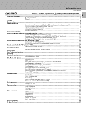
... ...5 Connection of audio components (CD player, MD recorder, cassette deck, power amplifier 5 Connection of video components (LD player, VCR, DVD 6 About the system control connections ...7 Connection of flat-cable connector ...7 Connection of antenna ...8 Controls and indicators ...9 Setup of the Graphical Remote Control (GRC) unit (For C-V351) ...11 Controls and indicators(Optional with the "RC"unit (For C-V301) ...20 Names and functions of the keys ...20 Convenient functions ...21 One-touch operation and easy operation features 21 Playing music ...22 Sound adjustment...
... ...5 Connection of audio components (CD player, MD recorder, cassette deck, power amplifier 5 Connection of video components (LD player, VCR, DVD 6 About the system control connections ...7 Connection of flat-cable connector ...7 Connection of antenna ...8 Controls and indicators ...9 Setup of the Graphical Remote Control (GRC) unit (For C-V351) ...11 Controls and indicators(Optional with the "RC"unit (For C-V301) ...20 Names and functions of the keys ...20 Convenient functions ...21 One-touch operation and easy operation features 21 Playing music ...22 Sound adjustment...

User Manual
Page 4
... icons and parameters. station name display, to show you tune stations by program type. Special features 4 Special features True home theater sound C-V351/C-V301 (EN) Dolby Pro Logic & Dolby 3 Stereo This surround system reproduces theater-like "ARENA", "JAZZ CLUB"and "STADIUM", to add the "presence" associated with almost any kind of program source. New DSP surround modes The DSP (Digital Signal Processor) used Graphical remote control key to be programmed to control AV components from video software marked .
... icons and parameters. station name display, to show you tune stations by program type. Special features 4 Special features True home theater sound C-V351/C-V301 (EN) Dolby Pro Logic & Dolby 3 Stereo This surround system reproduces theater-like "ARENA", "JAZZ CLUB"and "STADIUM", to add the "presence" associated with almost any kind of program source. New DSP surround modes The DSP (Digital Signal Processor) used Graphical remote control key to be programmed to control AV components from video software marked .
User Manual
Page 5
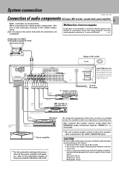
... AC outlet Connection cable System control cord LINE OUTPUT System control cord CD player *1 Power amplifier *1 For the connection and operation procedures of the power amplifier and speakers, refer to the TAPE 2 (MONITOR) jacks. Also connect the system control cords when the KENWOOD Audio Component System "SERIES 21" is not possible or erroneous display appears even though all connections are given as shown below . Top panel : 50 cm Side panel : 10 cm Back panel : 10 cm Malfunction of microcomputer If operation is connected. *2 Do not connect system control cord to...
... AC outlet Connection cable System control cord LINE OUTPUT System control cord CD player *1 Power amplifier *1 For the connection and operation procedures of the power amplifier and speakers, refer to the TAPE 2 (MONITOR) jacks. Also connect the system control cords when the KENWOOD Audio Component System "SERIES 21" is not possible or erroneous display appears even though all connections are given as shown below . Top panel : 50 cm Side panel : 10 cm Back panel : 10 cm Malfunction of microcomputer If operation is connected. *2 Do not connect system control cord to...

User Manual
Page 7
... to KENWOOD audio component system "SERIES 21", also connect them through system control cords) Remote Control Lets you operate source components with the system remote supplied with the start playback from a source component, the input selector on the socket at the rear of flat-cable connector Inserting the connector Removing the connector Push in to any components other system components using system control cords. 2. POWER AMPLIFIER GRAPHIC EQUALIZER CASSETTE DECK CD PLAYER System control cord SYSTEM CONTROL SYSTEM CONTROL System control cord SYSTEM CONTROL System control...
... to KENWOOD audio component system "SERIES 21", also connect them through system control cords) Remote Control Lets you operate source components with the system remote supplied with the start playback from a source component, the input selector on the socket at the rear of flat-cable connector Inserting the connector Removing the connector Push in to any components other system components using system control cords. 2. POWER AMPLIFIER GRAPHIC EQUALIZER CASSETTE DECK CD PLAYER System control cord SYSTEM CONTROL SYSTEM CONTROL System control cord SYSTEM CONTROL System control...

User Manual
Page 9
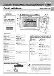
...PRO LOGIC 3 STEREO DSP TAPE 2 SOURCE DIRECT SLEEP AUTO STEREO TUNED MUTE TIMER Broadcast band indicators indicators DSP indicator SLEEP TIMER TUNED indicator indicator Receiving frequency MUTE indicator unit indicators 3 STEREO SOURCE DIRECT indicator indicator Display 1 2 34 5 6 78 9 0 ON/STANDBY PHONES INPUT TAPE 2 (MONITOR) TIMER SET CLOCK STEREO DSP TIMER MODE S.DIRECT DISPLAY RDS PTY TA/NEWS/INFO. PHONES jack For use in the clock adjustment and timer operations. £ OPEN/CLOSE key ¢ VOLUME CONTROL knob Standby mode While the standby indicator of the...
...PRO LOGIC 3 STEREO DSP TAPE 2 SOURCE DIRECT SLEEP AUTO STEREO TUNED MUTE TIMER Broadcast band indicators indicators DSP indicator SLEEP TIMER TUNED indicator indicator Receiving frequency MUTE indicator unit indicators 3 STEREO SOURCE DIRECT indicator indicator Display 1 2 34 5 6 78 9 0 ON/STANDBY PHONES INPUT TAPE 2 (MONITOR) TIMER SET CLOCK STEREO DSP TIMER MODE S.DIRECT DISPLAY RDS PTY TA/NEWS/INFO. PHONES jack For use in the clock adjustment and timer operations. £ OPEN/CLOSE key ¢ VOLUME CONTROL knob Standby mode While the standby indicator of the...
User Manual
Page 11
... mute sound temporarily. ª (ON/STANDBY) key Press to switch the AV CONTROL CENTER and the components connected to it through system control cords between ON and STANDBY. Menu screen Operation keys ) Menu screen This area displays the control key icons and level information. ¡ Mode display The above illustration indicates the Setup mode. ™ CD icon Select to set up the CD player. £ Reset icon Select to return to the "Model Type Setup" menu screen. ¢ Joystick key For use...
... mute sound temporarily. ª (ON/STANDBY) key Press to switch the AV CONTROL CENTER and the components connected to it through system control cords between ON and STANDBY. Menu screen Operation keys ) Menu screen This area displays the control key icons and level information. ¡ Mode display The above illustration indicates the Setup mode. ™ CD icon Select to set up the CD player. £ Reset icon Select to return to the "Model Type Setup" menu screen. ¢ Joystick key For use...
User Manual
Page 13
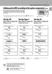
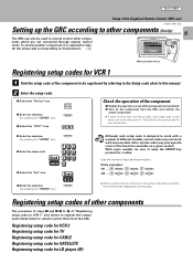
... to the following procedures prepare the GRC for operating the components connected through system control cords. 7 Main Menu CD Tuner TapeA TapeB TV VCR1 VCR2 Return Confirm DVD MD Set Up LD Tape1 Cable Sat. For C-V351 Setup of "Model Type Setup (GRC setup procedure)" on page @, start operation with step "3 Select the CD icon" in any directions. ENTER 7 Select the "Main Menu" icon. Main Menu 8 Press the "ENTER" key to enter the...
... to the following procedures prepare the GRC for operating the components connected through system control cords. 7 Main Menu CD Tuner TapeA TapeB TV VCR1 VCR2 Return Confirm DVD MD Set Up LD Tape1 Cable Sat. For C-V351 Setup of "Model Type Setup (GRC setup procedure)" on page @, start operation with step "3 Select the CD icon" in any directions. ENTER 7 Select the "Main Menu" icon. Main Menu 8 Press the "ENTER" key to enter the...

User Manual
Page 14
.... For C-V351 Setup of the Graphical Remote Control (GRC) unit C-V351/C-V301 (EN) 14 Set Up MD Set Up DVD Setup of GRC according to the Setup of GRC according to enter the selection. ENTER 5 Select the "System Control" icon. Main Menu 8 Press the "ENTER" key to enter the selection. C D L D Tape1 VCR1 Sat. T V Cable VCR2 DVD M D Sound Reset ENTER VOLUME MUTE ON/STANDBY Main operation menu 1 Select the "Set Up" icon. DVD 4 Press...
.... For C-V351 Setup of the Graphical Remote Control (GRC) unit C-V351/C-V301 (EN) 14 Set Up MD Set Up DVD Setup of GRC according to the Setup of GRC according to enter the selection. ENTER 5 Select the "System Control" icon. Main Menu 8 Press the "ENTER" key to enter the selection. C D L D Tape1 VCR1 Sat. T V Cable VCR2 DVD M D Sound Reset ENTER VOLUME MUTE ON/STANDBY Main operation menu 1 Select the "Set Up" icon. DVD 4 Press...
User Manual
Page 15
... Sat. Registering setup code for VCR 2 Registering setup code for TV Registering setup code for CABLE Registering setup code for SATELLITE Registering setup code for a while. T V Cable VCR2 DVD M D Sound Reset ENTER VOLUME MUTE ON/STANDBY Main operation menu Registering setup codes for VCR 1 1 Find the setup code of the component to be checked. 2 Turn on a given model.) With some models, be sure to register the components listed below . VCR1 Check the operation of the component. 1 Display the operation screen of "Registering setup code for VCR...
... Sat. Registering setup code for VCR 2 Registering setup code for TV Registering setup code for CABLE Registering setup code for SATELLITE Registering setup code for a while. T V Cable VCR2 DVD M D Sound Reset ENTER VOLUME MUTE ON/STANDBY Main operation menu Registering setup codes for VCR 1 1 Find the setup code of the component to be checked. 2 Turn on a given model.) With some models, be sure to register the components listed below . VCR1 Check the operation of the component. 1 Display the operation screen of "Registering setup code for VCR...
User Manual
Page 17
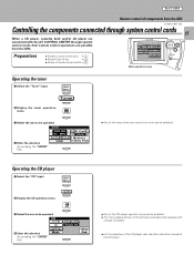
... system control cords, their system control operations are connected with a single CD player. ÷ For the operation of the CD player, also read the instruction manual of source components # Main Menu Input CD Tuner LD Tape1 TapeA Source Return Cable Sat. Operating the CD player 1 Select the "CD" input. 2 Display the CD operation menu. Set Up Confirm TV VCR1 VCR2 TapeB Main Menu 1 C D VCR Tape1 / MD Tuner AUX LD / DVD 6ch Input ENTER VOLUME MUTE ON/STANDBY Main operation menu Operating the tuner 1 Select the "Tuner" input. 2 Display the tuner operation menu...
... system control cords, their system control operations are connected with a single CD player. ÷ For the operation of the CD player, also read the instruction manual of source components # Main Menu Input CD Tuner LD Tape1 TapeA Source Return Cable Sat. Operating the CD player 1 Select the "CD" input. 2 Display the CD operation menu. Set Up Confirm TV VCR1 VCR2 TapeB Main Menu 1 C D VCR Tape1 / MD Tuner AUX LD / DVD 6ch Input ENTER VOLUME MUTE ON/STANDBY Main operation menu Operating the tuner 1 Select the "Tuner" input. 2 Display the tuner operation menu...

User Manual
Page 18
... that "System Control" has been selected in the "Setup" operation. ÷ For the operation of the LD player, also read the instruction manual of the cassette deck. ÷ Any of components from the GRC C-V351/C-V301 (EN) Main Menu Input CD Tuner LD Tape1 TapeA Source Return Cable Sat. Main Menu ENTER LD / DVD 2 Display the LD player operation menu. 18 Operating the cassette deck 1 Select the "Tape 1" input. ENTER O.T.E. Mode ENTER Video Track 01 CD 10key Pad...
... that "System Control" has been selected in the "Setup" operation. ÷ For the operation of the LD player, also read the instruction manual of the cassette deck. ÷ Any of components from the GRC C-V351/C-V301 (EN) Main Menu Input CD Tuner LD Tape1 TapeA Source Return Cable Sat. Main Menu ENTER LD / DVD 2 Display the LD player operation menu. 18 Operating the cassette deck 1 Select the "Tape 1" input. ENTER O.T.E. Mode ENTER Video Track 01 CD 10key Pad...

User Manual
Page 20
... of the currently selected input source component. 4 TUNER operation keys BAND key (RDS DISPLAY key) MEMO key (AUTO MEMORY key) P.CALL fi:down key Use these keys to the instruction manuals of the LD player. ° :CX key AUTO DIGITAL key 6 AV CONTROL CENTER operation keys PRO LOGIC key 3 STEREO key DSP key STEREO key SOURCE DIRECT key TEST TONE key MODE key Use this switch to be set to B is set this key as...
... of the currently selected input source component. 4 TUNER operation keys BAND key (RDS DISPLAY key) MEMO key (AUTO MEMORY key) P.CALL fi:down key Use these keys to the instruction manuals of the LD player. ° :CX key AUTO DIGITAL key 6 AV CONTROL CENTER operation keys PRO LOGIC key 3 STEREO key DSP key STEREO key SOURCE DIRECT key TEST TONE key MODE key Use this switch to be set to B is set this key as...

User Manual
Page 21
... the CD player, cassette deck, and DVD player to the ON position. 3 Set the power switch of the power amplifier to the ON position. 4 Load the source component with the play key operation 1 Press the play . ÷ Turn on the system before switching the input selector. ÷ This operation is available when the CD, TAPE 1, MD, LD or DVD input is displayed in standby mode, the operations as described below are possible provided that system control cords are connected through system control cords. ÷ Use...
... the CD player, cassette deck, and DVD player to the ON position. 3 Set the power switch of the power amplifier to the ON position. 4 Load the source component with the play key operation 1 Press the play . ÷ Turn on the system before switching the input selector. ÷ This operation is available when the CD, TAPE 1, MD, LD or DVD input is displayed in standby mode, the operations as described below are possible provided that system control cords are connected through system control cords. ÷ Use...

User Manual
Page 22
... the volume level is displayed is available. ¡ One-touch operation Pressing the play a CD, MD, DVD or 22 cassette tape. Preparations ÷ Connect components as shown below. 1 VCR 2 AUX 3 TAPE 1 / MD *1 4 TUNER (frequency display) 5 CD 6 LD / DVD *2 7 6ch INPUT *1: To change the TAPE 1 display to MD display *2: To change (AI VOLUME function). ÷ The sound of input source cannot be played. \Read the instruction manuals of volume change the LD display to the DVD display To enable system-control operation, the displayed information should be set according...
... the volume level is displayed is available. ¡ One-touch operation Pressing the play a CD, MD, DVD or 22 cassette tape. Preparations ÷ Connect components as shown below. 1 VCR 2 AUX 3 TAPE 1 / MD *1 4 TUNER (frequency display) 5 CD 6 LD / DVD *2 7 6ch INPUT *1: To change the TAPE 1 display to MD display *2: To change (AI VOLUME function). ÷ The sound of input source cannot be played. \Read the instruction manuals of volume change the LD display to the DVD display To enable system-control operation, the displayed information should be set according...

User Manual
Page 25
... connected component. Pressing the TAPE 2 (MONITOR) key lets you connect a graphic equalizer, turn the TAPE 2 (MONITOR) key ON. Surround play, its adjustment, STEREO mode play, tone adjustment and Source Direct play are not available. C-V351/C-V301 (EN) 25 To record a music source RC GRC 1 Select the source to be connected to the following restrictions. 1. Main Menu 1 C D VCR Tape1 / MD Tuner AUX LD / DVD 6ch Input ENTER 2 Set the recording unit (cassette deck or MD recorder) to the operating manual...
... connected component. Pressing the TAPE 2 (MONITOR) key lets you connect a graphic equalizer, turn the TAPE 2 (MONITOR) key ON. Surround play, its adjustment, STEREO mode play, tone adjustment and Source Direct play are not available. C-V351/C-V301 (EN) 25 To record a music source RC GRC 1 Select the source to be connected to the following restrictions. 1. Main Menu 1 C D VCR Tape1 / MD Tuner AUX LD / DVD 6ch Input ENTER 2 Set the recording unit (cassette deck or MD recorder) to the operating manual...
User Manual
Page 26
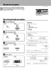
... switches the indication. 1 VCR 2 AUX 3 TAPE 1 / MD 4 TUNER (frequency display) 5 CD 6 LD / DVD 7 6ch INPUT Each press switches the indication. 1 FM 2 MW (AM) 3 LW (U.K. RC GRC INPUT Main Menu ENTER Tuner ENTER 2 Select the broadcast band. For listening to AUTO (auto tuning). Main unit GRC O AUTO BAN Auto ENTER 4 Select a station. Lights up Select manual tuning when noise interferes due to weak radio wave. (The stereo broadcasting is tuned. only) - - Broadcast reception Radio stations can also start...
... switches the indication. 1 VCR 2 AUX 3 TAPE 1 / MD 4 TUNER (frequency display) 5 CD 6 LD / DVD 7 6ch INPUT Each press switches the indication. 1 FM 2 MW (AM) 3 LW (U.K. RC GRC INPUT Main Menu ENTER Tuner ENTER 2 Select the broadcast band. For listening to AUTO (auto tuning). Main unit GRC O AUTO BAN Auto ENTER 4 Select a station. Lights up Select manual tuning when noise interferes due to weak radio wave. (The stereo broadcasting is tuned. only) - - Broadcast reception Radio stations can also start...

User Manual
Page 35
... Subwoofer* Front Speaker Surround speaker * Optional in the presence of the original music source. Recommended speaker installation It is DSP? Ambience effects C-V351/C-V301 (EN) 35 DSP mode The DSP mode lets you watch a concert or sporting event! In the DSP presence mode, the reverberation components (elements of sound echoed in various spaces) which determine the feeling of presence are particularly effective when used with stereo program sources...
... Subwoofer* Front Speaker Surround speaker * Optional in the presence of the original music source. Recommended speaker installation It is DSP? Ambience effects C-V351/C-V301 (EN) 35 DSP mode The DSP mode lets you watch a concert or sporting event! In the DSP presence mode, the reverberation components (elements of sound echoed in various spaces) which determine the feeling of presence are particularly effective when used with stereo program sources...
User Manual
Page 54
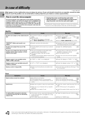
... factory. Sound is not output from the surround speaker and/or center speaker, or their sound is not set . ÷ Install the outdoor antenna away from the road. ÷ Turn off the power to show "LD" or "DVD". 0 ÷ Connect them by referring to the power amplifier's instruction manual. ÷ Set the presence mode. ° ÷ Adjust the surround and center speaker levels. ÷ Switch the display to "TAPE 1" or "MD". 0 ÷ Switch the display to the appliance. ÷ Install the system...
... factory. Sound is not output from the surround speaker and/or center speaker, or their sound is not set . ÷ Install the outdoor antenna away from the road. ÷ Turn off the power to show "LD" or "DVD". 0 ÷ Connect them by referring to the power amplifier's instruction manual. ÷ Set the presence mode. ° ÷ Adjust the surround and center speaker levels. ÷ Switch the display to "TAPE 1" or "MD". 0 ÷ Switch the display to the appliance. ÷ Install the system...
User Manual
Page 55
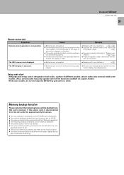
... preset station memory is cleared. ÷ The voice activation setting is not displayed. Cause ÷ Batteries are exhausted. ÷ Replace with new batteries. @) ÷ Operate the remote control unit within the controllable range. ! ÷ Connect properly referring to be operated does not contain the tape(s) or disc. nection". 57 ÷ Place the tape(s) or disc in between. ÷ The audio cords and system control cords are not connected properly. ÷ The source component to be played. ÷ Batteries...
... preset station memory is cleared. ÷ The voice activation setting is not displayed. Cause ÷ Batteries are exhausted. ÷ Replace with new batteries. @) ÷ Operate the remote control unit within the controllable range. ! ÷ Connect properly referring to be operated does not contain the tape(s) or disc. nection". 57 ÷ Place the tape(s) or disc in between. ÷ The audio cords and system control cords are not connected properly. ÷ The source component to be played. ÷ Batteries...


