Operation Manual
Page 1
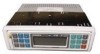
... COMPACT DIGITAL AUDIO CH MCD-9424JA W1 1 W2 2 LOUD W3 3 RPT 4 DISP SHF 5 SCN 6 PWR Welcome! If you how to install your Jensen stereo to have the original dated receipt. MCD 9424JA Features Basic Operation 2 On/Off 2 Select Mode 2 Volume 2 Treble 2 Bass 3 Balance 3 Fader 3 Bass Boost 3 Set the Clock 3 Optional Remote Control ..... 4 WeatherBand and Radio Operation 5 Select a Weather Band ........ 5 Select a Radio Band 5 Select a Radio Station ......... 5 Preset Stations 6 Automatically Store Stations 6 Preset Scan 6 CD Player Operation ........ 7 Insert and Eject CD...
... COMPACT DIGITAL AUDIO CH MCD-9424JA W1 1 W2 2 LOUD W3 3 RPT 4 DISP SHF 5 SCN 6 PWR Welcome! If you how to install your Jensen stereo to have the original dated receipt. MCD 9424JA Features Basic Operation 2 On/Off 2 Select Mode 2 Volume 2 Treble 2 Bass 3 Balance 3 Fader 3 Bass Boost 3 Set the Clock 3 Optional Remote Control ..... 4 WeatherBand and Radio Operation 5 Select a Weather Band ........ 5 Select a Radio Band 5 Select a Radio Station ......... 5 Preset Stations 6 Automatically Store Stations 6 Preset Scan 6 CD Player Operation ........ 7 Insert and Eject CD...
Operation Manual
Page 2
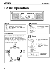
... COMPACT DIGITAL AUDIO CH MCD-9424JA W1 1 W2 2 LOUD W3 3 RPT 4 DISP SHF 5 SCN 6 PWR On/Off PWR Press PWR button to turn it off. Adjust Treble level using VOL or VOL button. +7 = maximum - 7 = minimum SEL/ (Balance) (Bass) 2 Press SEL button two times. 2 VOL VOL 2. VOL Treble 1 SEL/ 1. When mode has not been adjusted for 3 seconds, display returns to move display through volume, treble, bass, balance and fader functions. Use VOL and VOL buttons to adjust...
... COMPACT DIGITAL AUDIO CH MCD-9424JA W1 1 W2 2 LOUD W3 3 RPT 4 DISP SHF 5 SCN 6 PWR On/Off PWR Press PWR button to turn it off. Adjust Treble level using VOL or VOL button. +7 = maximum - 7 = minimum SEL/ (Balance) (Bass) 2 Press SEL button two times. 2 VOL VOL 2. VOL Treble 1 SEL/ 1. When mode has not been adjusted for 3 seconds, display returns to move display through volume, treble, bass, balance and fader functions. Use VOL and VOL buttons to adjust...
Operation Manual
Page 3
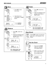
... button. +7 = maximum VOL - 7 = minimum Balance F15 = Front speakers only R15 = Rear speakers only 1 SEL/ 2 VOL 1. VOL R15 = Right speaker only L15 = Left speaker only Set the Clock 1 DISP 3 Sec 2 3 Sec 01 2 3 1. Within 3 seconds, press to change minutes, to increase the bass output. Adjust sound balance front and rear using VOL or VOL button. LOUD appears in the display. Press and hold DISP button for 3 seconds until display flashes. 2. MH 3 Press SEL button four times. 2. Adjust Bass level using...
... button. +7 = maximum VOL - 7 = minimum Balance F15 = Front speakers only R15 = Rear speakers only 1 SEL/ 2 VOL 1. VOL R15 = Right speaker only L15 = Left speaker only Set the Clock 1 DISP 3 Sec 2 3 Sec 01 2 3 1. Within 3 seconds, press to change minutes, to increase the bass output. Adjust sound balance front and rear using VOL or VOL button. LOUD appears in the display. Press and hold DISP button for 3 seconds until display flashes. 2. MH 3 Press SEL button four times. 2. Adjust Bass level using...
Operation Manual
Page 4
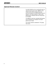
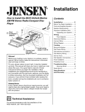
® Optional Remote Control MCD 9424JA The MCD 9424JA can be installed in the dash panel of your vessel. The remote requires a standard 2 1/8" gauge hole cutout. 4 The remote control allows access to be controlled through an optional wired remote control, MWR-20. The MWR-20 looks like a standard dash gauge and is designed to the most common functions on the MCD 9424JA such as Volume, Tune/Track selection, Power on/off, AM/FM bands, Weather Band and Play/Pause for CD Mode.
® Optional Remote Control MCD 9424JA The MCD 9424JA can be installed in the dash panel of your vessel. The remote requires a standard 2 1/8" gauge hole cutout. 4 The remote control allows access to be controlled through an optional wired remote control, MWR-20. The MWR-20 looks like a standard dash gauge and is designed to the most common functions on the MCD 9424JA such as Volume, Tune/Track selection, Power on/off, AM/FM bands, Weather Band and Play/Pause for CD Mode.
Operation Manual
Page 5
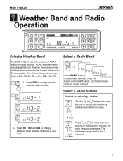
... bands. Select a Radio Station Options for selecting a station Touch a or for more than one second to move quickly through the radio frequency numbers. W3 3 2. Press WB to change radio to weather radio receiver. 2 W1 1 W2 2 Select a Radio Band BAND Press BAND button to six preset stations. The numbers change radio between three weather channels in your area. 1 Sec Press or for less than one step. NOAA Weather Radio broadcasts National Weather Service warnings...
... bands. Select a Radio Station Options for selecting a station Touch a or for more than one second to move quickly through the radio frequency numbers. W3 3 2. Press WB to change radio to weather radio receiver. 2 W1 1 W2 2 Select a Radio Band BAND Press BAND button to six preset stations. The numbers change radio between three weather channels in your area. 1 Sec Press or for less than one step. NOAA Weather Radio broadcasts National Weather Service warnings...
Operation Manual
Page 6
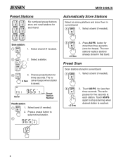
... stations replace stations >3 Sec already stored in current band 1 BAND 1. Preset Scan Scan stations stored in that band. Select a band (if needed ). 2. Select a station. Press a preset button for more than three seconds (receiver beeps). Select band (if needed ). 2 AS/PS Press AS/PS button for three seconds. The re- 3 Sec ceiver beeps when station is saved. Select a band (if needed ). 2 2. ® MCD 9424JA Preset Stations W1 1 W2 2 W3 3 RPT 4 Six numbered preset buttons...
... stations replace stations >3 Sec already stored in current band 1 BAND 1. Preset Scan Scan stations stored in that band. Select a band (if needed ). 2. Select a station. Press a preset button for more than three seconds (receiver beeps). Select band (if needed ). 2 AS/PS Press AS/PS button for three seconds. The re- 3 Sec ceiver beeps when station is saved. Select a band (if needed ). 2 2. ® MCD 9424JA Preset Stations W1 1 W2 2 W3 3 RPT 4 Six numbered preset buttons...
Operation Manual
Page 7
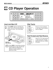
... advance to radio operation. xxxx x xx xx xxxx xxx Insert CD label side up Press OPEN to open flip-over panel. Track numbers show on display. Receiver switches to next track. xx xxx Fast Forward and Fast Reverse Hold or to fast forward or fast reverse CD. Press (eject) to stop CD play and eject CD from when you release the button. 7 CD play . Flip panel up to...
... advance to radio operation. xxxx x xx xx xxxx xxx Insert CD label side up Press OPEN to open flip-over panel. Track numbers show on display. Receiver switches to next track. xx xxx Fast Forward and Fast Reverse Hold or to fast forward or fast reverse CD. Press (eject) to stop CD play and eject CD from when you release the button. 7 CD play . Flip panel up to...
Operation Manual
Page 8
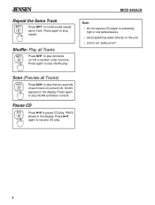
... all tracks on CD in random order one time. Press again to play . 8 SCAN appears in the display. MCD 9424JA Note: • Do not expose CD player to continuously repeat same track. ® Repeat the Same Track RPT 4 Press RPT to extremely high or low temperatures. • Avoid splashing water directly on the unit. • Unit is not "water...
... all tracks on CD in random order one time. Press again to play . 8 SCAN appears in the display. MCD 9424JA Note: • Do not expose CD player to continuously repeat same track. ® Repeat the Same Track RPT 4 Press RPT to extremely high or low temperatures. • Avoid splashing water directly on the unit. • Unit is not "water...
Operation Manual
Page 9
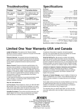
... sensitivity (stereo 16 dBf Stereo separation @ 1 kHz 40 dB AM Tuner Tuning range 530 kHz-1720 kHz Amplifier Total system power 160 watts peak Power output front: 2 x 40W rear: 2 x 40W General Power supply 11-16 VDC, negative ground Speaker output impedance 4-8 Ohms Fuses fast blow AGC (0.5 amp and 10 amp) Dimensions 7" x 7" x 2" (178mm x 178mm x 51mm) Specifications subject to you may also have other electrical interferences; Persons Protected. The...
... sensitivity (stereo 16 dBf Stereo separation @ 1 kHz 40 dB AM Tuner Tuning range 530 kHz-1720 kHz Amplifier Total system power 160 watts peak Power output front: 2 x 40W rear: 2 x 40W General Power supply 11-16 VDC, negative ground Speaker output impedance 4-8 Ohms Fuses fast blow AGC (0.5 amp and 10 amp) Dimensions 7" x 7" x 2" (178mm x 178mm x 51mm) Specifications subject to you may also have other electrical interferences; Persons Protected. The...
Operation Manual
Page 10
...3 Connect Wires 3 Wiring Diagram 4 Testing 5 Reconnect Battery 5 Test Power Wiring 5 Test Antenna Connection 5 Test Memory Wiring 5 Set the Clock 5 Test Speaker Connections ......... 6 Final Installation 7 Protective Cover 7 Troubleshooting 8 • Securing Wires 8 Reset Button 8 Specifications and Warranty 9 Technical Assistance For technical assistance with the installation of these instructions before you ever need to work right, it . We've tried to install your Jensen stereo should ever require service, you will show you 're holding in this book, consider turning...
...3 Connect Wires 3 Wiring Diagram 4 Testing 5 Reconnect Battery 5 Test Power Wiring 5 Test Antenna Connection 5 Test Memory Wiring 5 Set the Clock 5 Test Speaker Connections ......... 6 Final Installation 7 Protective Cover 7 Troubleshooting 8 • Securing Wires 8 Reset Button 8 Specifications and Warranty 9 Technical Assistance For technical assistance with the installation of these instructions before you ever need to work right, it . We've tried to install your Jensen stereo should ever require service, you will show you 're holding in this book, consider turning...
Operation Manual
Page 11
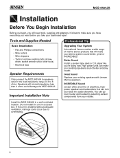
... power units can turn your boat into audio dynamite. ® MCD 9424JA Installation Before You Begin Installation Before you begin, you will make your existing speakers sound better and play louder. Important Installation Note Upgrading Your System International Jensen makes a wide range of amplifiers, highpower speakers and subwoofers that will need before you take your dashboard apart. If the unit is best to 8 ohms. Speakers with Jensen Marine speakers. Great Sound Replace your retailer. Install...
... power units can turn your boat into audio dynamite. ® MCD 9424JA Installation Before You Begin Installation Before you begin, you will make your existing speakers sound better and play louder. Important Installation Note Upgrading Your System International Jensen makes a wide range of amplifiers, highpower speakers and subwoofers that will need before you take your dashboard apart. If the unit is best to 8 ohms. Speakers with Jensen Marine speakers. Great Sound Replace your retailer. Install...
Operation Manual
Page 12
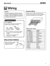
Speaker RF+ Speaker RF- Wiring Color Codes Function LF+ Speaker LF- Speaker RR+ Speaker RR- Fuse Fuse Adapter Crimp on Ground Ignition Battery Dimmer Color white white/black green green/black gray gray/black violet violet/black dark blue black red yellow orange 3 ® MCD 9424JA Wiring Important If wiring connections are made wrong, the unit will not operate properly and it could be damaged. Speaker Remote-Amp turn on a matching connector and attach: • Yellow wire-Fuse marked...
Speaker RF+ Speaker RF- Wiring Color Codes Function LF+ Speaker LF- Speaker RR+ Speaker RR- Fuse Fuse Adapter Crimp on Ground Ignition Battery Dimmer Color white white/black green green/black gray gray/black violet violet/black dark blue black red yellow orange 3 ® MCD 9424JA Wiring Important If wiring connections are made wrong, the unit will not operate properly and it could be damaged. Speaker Remote-Amp turn on a matching connector and attach: • Yellow wire-Fuse marked...
Operation Manual
Page 13
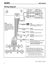
.../black green LR+ LR Dark Blue Amp AMP Connect to existing dimmer wire. Fuses When replacing a fuse, make sure new fuse is always live. Orange Dimmer Connect to the amplifier. Accessory Connect to ground terminal. Memory Connect to battery or 12 volt power source that is correct type and amperage. Using an incorrect fuse could damage radio. Black Filter Box In-line Fuse (10-amp) Red Ground Connect to existing radio wire or radio fuse. violet/black violet RR+ RR...
.../black green LR+ LR Dark Blue Amp AMP Connect to existing dimmer wire. Fuses When replacing a fuse, make sure new fuse is always live. Orange Dimmer Connect to the amplifier. Accessory Connect to ground terminal. Memory Connect to battery or 12 volt power source that is correct type and amperage. Using an incorrect fuse could damage radio. Black Filter Box In-line Fuse (10-amp) Red Ground Connect to existing radio wire or radio fuse. violet/black violet RR+ RR...
Operation Manual
Page 14
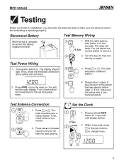
Reconnect Battery Test Memory Wiring When wiring is operating properly. Turn the key off, then turn the radio on. Test Power Wiring 1. If not, check the electrical connection at the yellow and red wires. 3. You will select a different station. 2. Test Antenna Connection 1 1. The radio should tune to change minutes, to a nearby station. Set the Clock 1 DISP 3 Sec 2 3 Sec 01 2 3 1. Turn ignition switch on again. If not, check antenna con- Press and hold button 1 for 3 seconds until you...
Reconnect Battery Test Memory Wiring When wiring is operating properly. Turn the key off, then turn the radio on. Test Power Wiring 1. If not, check the electrical connection at the yellow and red wires. 3. You will select a different station. 2. Test Antenna Connection 1 1. The radio should tune to change minutes, to a nearby station. Set the Clock 1 DISP 3 Sec 2 3 Sec 01 2 3 1. Turn ignition switch on again. If not, check antenna con- Press and hold button 1 for 3 seconds until you...
Operation Manual
Page 15
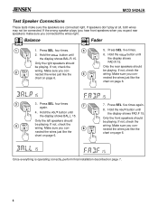
... operating correctly, perform final installation described on page 6. 5 SEL/ 6 VOL 5. Press SEL four times. 2. If not, check the wiring. Make sure you connected the wires right. Hold the VOL button until the display shows FAD.F 15. Balance Fader 1 SEL/ 2 VOL 1. If speakers don't play at all, both wires may not be playing. If the wrong speaker plays (you hear front speakers when you expect rear speakers) make sure the speakers are connected...
... operating correctly, perform final installation described on page 6. 5 SEL/ 6 VOL 5. Press SEL four times. 2. If not, check the wiring. Make sure you connected the wires right. Hold the VOL button until the display shows FAD.F 15. Balance Fader 1 SEL/ 2 VOL 1. If speakers don't play at all, both wires may not be playing. If the wrong speaker plays (you hear front speakers when you expect rear speakers) make sure the speakers are connected...
Operation Manual
Page 16
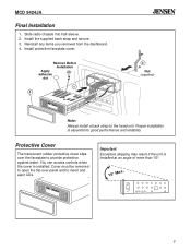
... CH COMPACT DIGITAL AUDIO MCD-9424JA W1 1 W3 3 SHF 5 W2 2 RPT 4 SCN 6 LOUD DISP PWR Important Excessive skipping may result if the unit is essential for good performance and reliability. You can access controls when the cover is installed. Slide radio chassis into half-sleeve. 2. Cover must be removed to open the flip-over the faceplate to the head unit.
... CH COMPACT DIGITAL AUDIO MCD-9424JA W1 1 W3 3 SHF 5 W2 2 RPT 4 SCN 6 LOUD DISP PWR Important Excessive skipping may result if the unit is essential for good performance and reliability. You can access controls when the cover is installed. Slide radio chassis into half-sleeve. 2. Cover must be removed to open the flip-over the faceplate to the head unit.
Operation Manual
Page 17
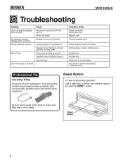
Use wire ties to bundle wires together when possible. (But never bundle speaker wires and power wires together!) Reset Button In case of your installation! ® MCD 9424JA Troubleshooting Problem Does not operate (display does not light) No speakers operate (display lights normally) Not all speakers operate Blows fuses Can't find cause of problem Cause No power to red wire (12V with key on) Inline fuse blown Speaker wires not connected Incorrect splices or connections Speaker wires shorting to chassis ground or to...
Use wire ties to bundle wires together when possible. (But never bundle speaker wires and power wires together!) Reset Button In case of your installation! ® MCD 9424JA Troubleshooting Problem Does not operate (display does not light) No speakers operate (display lights normally) Not all speakers operate Blows fuses Can't find cause of problem Cause No power to red wire (12V with key on) Inline fuse blown Speaker wires not connected Incorrect splices or connections Speaker wires shorting to chassis ground or to...

Operation Manual
Page 18
... dBf 50 dB quieting sensitivity (stereo 16 dBf Stereo separation @ 1 kHz ...40 dB AM T uner Tuning range ...530 kHz-1720 kHz Amplifier Total system power ...160 watts peak Power output ...front: 2 x 40W rear: 2 x 40W General Power supply 11-16 VDC, negative ground Speaker output impedance 4-8 Ohms Fuses fast blow AGC (0.5 amp and 10 amp) Dimensions 7" x 7" x 2" (178mm x 178mm x 51mm) Specifications subject to the carrier); All implied...
... dBf 50 dB quieting sensitivity (stereo 16 dBf Stereo separation @ 1 kHz ...40 dB AM T uner Tuning range ...530 kHz-1720 kHz Amplifier Total system power ...160 watts peak Power output ...front: 2 x 40W rear: 2 x 40W General Power supply 11-16 VDC, negative ground Speaker output impedance 4-8 Ohms Fuses fast blow AGC (0.5 amp and 10 amp) Dimensions 7" x 7" x 2" (178mm x 178mm x 51mm) Specifications subject to the carrier); All implied...


