Operation Manual
Page 10
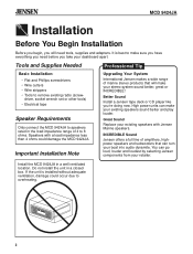
... unit for everyone. For your Jensen stereo to install your Jensen stereo should ever require service, you will show you how to work right, it . It's a good idea to Install the MCD 9424JA Marine AM/FM Stereo Radio/Compact Disc Player Final 3 Installation (page 8) 1 Install wiring 2 Connect and (pages 4 and 5) test radio (pages 6 and 7) Welcome! Warranty...
... unit for everyone. For your Jensen stereo to install your Jensen stereo should ever require service, you will show you how to work right, it . It's a good idea to Install the MCD 9424JA Marine AM/FM Stereo Radio/Compact Disc Player Final 3 Installation (page 8) 1 Install wiring 2 Connect and (pages 4 and 5) test radio (pages 6 and 7) Welcome! Warranty...
Operation Manual
Page 11
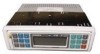
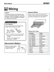
...and Phillips screwdrivers • Wire cutters • Wire strippers • Tools to remove existing radio (screwdriver, socket wrench set or other tools) • Electrical tape Speaker Requirements Only connect the MCD 9424JA to make sure you have everything you need tools, supplies and adapters. If ... before you take your existing speakers sound better and play louder. Install the MCD 9424JA in a closed box. Better Sound Install a Jensen tape deck or CD player like you will make your dashboard apart. OPEN VOL AS/PS VOL WB BAND SEL/ ® ST SHUFFLE 8 X OVERSAMPLING •...
...and Phillips screwdrivers • Wire cutters • Wire strippers • Tools to remove existing radio (screwdriver, socket wrench set or other tools) • Electrical tape Speaker Requirements Only connect the MCD 9424JA to make sure you have everything you need tools, supplies and adapters. If ... before you take your existing speakers sound better and play louder. Install the MCD 9424JA in a closed box. Better Sound Install a Jensen tape deck or CD player like you will make your dashboard apart. OPEN VOL AS/PS VOL WB BAND SEL/ ® ST SHUFFLE 8 X OVERSAMPLING •...
Operation Manual
Page 12
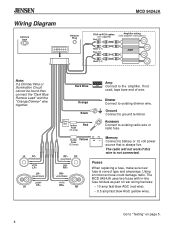
... Yellow wire-Fuse marked MAIN, BAT or PWR • Red wire-Fuse marked ACCY (accessory), or RADIO Disconnect Battery Before you begin, always disconnect the battery negative terminal. - + Connect Wires Splice, crimp or solder the wires from the receiver to the chart (below). Follow the installation... handled by an experienced technician. Speaker RF+ Speaker RF- Speaker LR+ Speaker LR- ® MCD 9424JA Wiring Important If wiring connections are made wrong, the unit will not operate properly and it could be damaged. Wiring Color Codes Function LF+ Speaker LF- Professional...
... Yellow wire-Fuse marked MAIN, BAT or PWR • Red wire-Fuse marked ACCY (accessory), or RADIO Disconnect Battery Before you begin, always disconnect the battery negative terminal. - + Connect Wires Splice, crimp or solder the wires from the receiver to the chart (below). Follow the installation... handled by an experienced technician. Speaker RF+ Speaker RF- Speaker LR+ Speaker LR- ® MCD 9424JA Wiring Important If wiring connections are made wrong, the unit will not operate properly and it could be damaged. Wiring Color Codes Function LF+ Speaker LF- Professional...
Operation Manual
Page 13
...Testing" on page 5. 4 In-line Yellow Fuse (0.5-amp) RF- Go to existing dimmer wire. green/black green LR+ LR Dark Blue Amp AMP Connect to existing radio wire or radio fuse. If not used, tape bare end of rear wiring harness: • 10 amp fast blow AGC (red wire). • 0.5 amp fast... violet RR+ RR +- Fuses When replacing a fuse, make sure new fuse is not connected. Accessory Connect to the amplifier. The MCD 9424JA uses two fuses with in-line fuse holders as part of wire. The radio will not work if this wire is correct type and amperage. LF LF- Using an...
...Testing" on page 5. 4 In-line Yellow Fuse (0.5-amp) RF- Go to existing dimmer wire. green/black green LR+ LR Dark Blue Amp AMP Connect to existing radio wire or radio fuse. If not used, tape bare end of rear wiring harness: • 10 amp fast blow AGC (red wire). • 0.5 amp fast... violet RR+ RR +- Fuses When replacing a fuse, make sure new fuse is not connected. Accessory Connect to the amplifier. The MCD 9424JA uses two fuses with in-line fuse holders as part of wire. The radio will not work if this wire is correct type and amperage. LF LF- Using an...
Operation Manual
Page 14
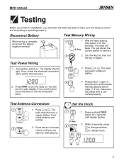
... just stored the current station in memory. 2 2. Press PWR to increase volume until display flashes. 2. If not, check electrical connections to change hours. Press or . Test Power Wiring 1. Press or . Test Antenna Connection 1 1. The radio should return to make sure the yellow wire is complete, reconnect the battery negative terminal. - + 1 W1 1 1. nection. 2 VOL...
... just stored the current station in memory. 2 2. Press PWR to increase volume until display flashes. 2. If not, check electrical connections to change hours. Press or . Test Power Wiring 1. Press or . Test Antenna Connection 1 1. The radio should return to make sure the yellow wire is complete, reconnect the battery negative terminal. - + 1 W1 1 1. nection. 2 VOL...
Operation Manual
Page 15
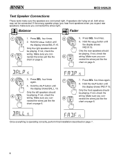
... on page 6. 7 SEL/ 8 VOL 7. If the wrong speaker plays (you hear front speakers when you expect rear speakers) make sure the speakers are connected right. Balance Fader 1 SEL/ 2 VOL 1. If not, check the wiring. If speakers don't play at all, both wires may not be playing. ...Press SEL five times. 6. If not, check the wiring. Only the left speakers should be connected. Hold the VOL button until the display shows BAL.L 15. Once everything is operating correctly, perform final installation described on page 6. ® MCD...
... on page 6. 7 SEL/ 8 VOL 7. If the wrong speaker plays (you hear front speakers when you expect rear speakers) make sure the speakers are connected right. Balance Fader 1 SEL/ 2 VOL 1. If not, check the wiring. If speakers don't play at all, both wires may not be playing. ...Press SEL five times. 6. If not, check the wiring. Only the left speakers should be connected. Hold the VOL button until the display shows BAL.L 15. Once everything is operating correctly, perform final installation described on page 6. ® MCD...
Operation Manual
Page 17
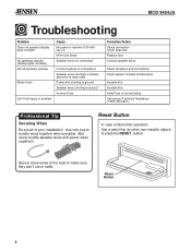
...boat to ground Incorrect fuse Corrective Action Check connection Check boat fuse Replace fuse Connect speaker wires Check all splices and connections Check splices, insulate all bare wires Insulate wire Insulate wire Install fuse of correct rating Call Jensen Technical Assistance (1-800-323-0221) Professional Tip... Securing Wires Be proud of problem Cause No power to red wire (12V with key on) Inline fuse blown Speaker wires not connected Incorrect splices or connections Speaker wires shorting to ...
...boat to ground Incorrect fuse Corrective Action Check connection Check boat fuse Replace fuse Connect speaker wires Check all splices and connections Check splices, insulate all bare wires Insulate wire Insulate wire Install fuse of correct rating Call Jensen Technical Assistance (1-800-323-0221) Professional Tip... Securing Wires Be proud of problem Cause No power to red wire (12V with key on) Inline fuse blown Speaker wires not connected Incorrect splices or connections Speaker wires shorting to ...


