Instructions
Page 2
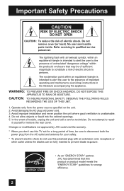
... and call a service technician. Avoid Improper installation and never position the unit where good ventilation is intended to alert the user to repair it yourself or remove the rear cover. Refer servicing to disconnect both the power plug from the power source specified on the unit. 2. Operate only from the AC outlet and antenna for energy efficiency. 2 Avoid damaging the AC plug and power cord. 3. WARNING...
... and call a service technician. Avoid Improper installation and never position the unit where good ventilation is intended to alert the user to repair it yourself or remove the rear cover. Refer servicing to disconnect both the power plug from the power source specified on the unit. 2. Operate only from the AC outlet and antenna for energy efficiency. 2 Avoid damaging the AC plug and power cord. 3. WARNING...
Instructions
Page 5
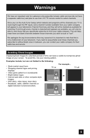
... a separate cable box) and plan to use their JVC TV remote control to note that you run the Auto Tuner Setup (which detects and programs all be able to view those channels you subscribe to without blank ones in between those channels you will likely mean there are not limited to sequentially scan those that this is important to select channels. Avoiding Ghost Images Displaying fixed...
... a separate cable box) and plan to use their JVC TV remote control to note that you run the Auto Tuner Setup (which detects and programs all be able to view those channels you subscribe to without blank ones in between those channels you will likely mean there are not limited to sequentially scan those that this is important to select channels. Avoiding Ghost Images Displaying fixed...
Instructions
Page 10
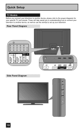
Quick Setup TV Models Before you in understanding how to connect your television to another device, please refer to set up your specific TV and remote. These will help assist you connect your television to another device, as well as use the remote to the proper diagrams for your television. Rear Panel Diagram AUDIO AUDIO AUDIO COMPONENT AUDIO COMPONENT AUDIO AUDIO AUDIO COMPONENT AUDIO COMPONENT INPUT 3 S-VIDEO Y VIDEO PB L PR R INPUT 4 INPUT 5 / INPUT 1 AUDIO AUDIO OUT Y VIDEO VIDEO PB L L L PR R R R Side Panel Diagram POWER INPUT 3 S-VIDEO Y VIDEO ...
Quick Setup TV Models Before you in understanding how to connect your television to another device, please refer to set up your specific TV and remote. These will help assist you connect your television to another device, as well as use the remote to the proper diagrams for your television. Rear Panel Diagram AUDIO AUDIO AUDIO COMPONENT AUDIO COMPONENT AUDIO AUDIO AUDIO COMPONENT AUDIO COMPONENT INPUT 3 S-VIDEO Y VIDEO PB L PR R INPUT 4 INPUT 5 / INPUT 1 AUDIO AUDIO OUT Y VIDEO VIDEO PB L L L PR R R R Side Panel Diagram POWER INPUT 3 S-VIDEO Y VIDEO ...
Instructions
Page 12
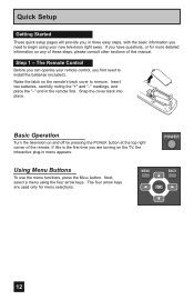
... the TV, the interactive plug-in menu appears. Snap the cover back into place. Basic Operation Turn the television on the remote's back cover to remove. If this manual. The four arrow keys are turning on any of these steps, please consult other sections of the remote. MENU BACK OK 12 The Remote Control Before you can operate your new television right away. Quick Setup Getting Started These quick setup...
... the TV, the interactive plug-in menu appears. Snap the cover back into place. Basic Operation Turn the television on the remote's back cover to remove. If this manual. The four arrow keys are turning on any of these steps, please consult other sections of the remote. MENU BACK OK 12 The Remote Control Before you can operate your new television right away. Quick Setup Getting Started These quick setup...
Instructions
Page 13
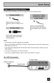
...local cable operator. • To connect a DVD player, see VCR Connection. • If you will use plugs like VCRs, DVD players, stereo amplifiers, game consoles, etc. Quick Setup Step 2 - Used to connect audio/video devices like the ones illustrated below. S-Video Cable Used to make these diagrams and the television does not work properly, contact your TV. No VCR Connection Cable or Antenna Output Coaxial Cable TV Rear Panel 75 Ω (VHF/UHF) DIGITAL AUDIO INPUT 1 OPTICAL OUT INPUT 2 PHOTO VIEWER / SERVICE 13 Connecting your devices To make video connections with S-Video...
...local cable operator. • To connect a DVD player, see VCR Connection. • If you will use plugs like VCRs, DVD players, stereo amplifiers, game consoles, etc. Quick Setup Step 2 - Used to connect audio/video devices like the ones illustrated below. S-Video Cable Used to make these diagrams and the television does not work properly, contact your TV. No VCR Connection Cable or Antenna Output Coaxial Cable TV Rear Panel 75 Ω (VHF/UHF) DIGITAL AUDIO INPUT 1 OPTICAL OUT INPUT 2 PHOTO VIEWER / SERVICE 13 Connecting your devices To make video connections with S-Video...
Instructions
Page 14
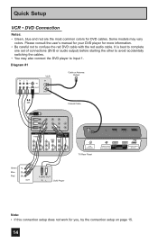
...vary colors. Diagram #1 R LV IN OUT VCR IN OUT Cable or Antenna Output OR Coaxial Cable AUDIO AUDIO AUDIO COMPONENT AUDIO COMPONENT INPUT 3 S-VIDEO Y VIDEO PB L PR R INPUT 4 Y VIDEO INPUT 5 / INPUT 1 AUDIO AUDIO OUT VIDEO PB L L L PR R R R 75 Ω (VHF/UHF) TV Rear Panel DIGITAL AUDIO INPUT 1 OPTICAL OUT INPUT 2 PHOTO VIEWER / SERVICE Green Blue Red Y PB PR OUT AUDIO OUT R L DVD Player Note: • If this connection setup does not work for DVD cables. Some models may also connect the DVD player to confuse the red DVD cable with the red audio cable.
...vary colors. Diagram #1 R LV IN OUT VCR IN OUT Cable or Antenna Output OR Coaxial Cable AUDIO AUDIO AUDIO COMPONENT AUDIO COMPONENT INPUT 3 S-VIDEO Y VIDEO PB L PR R INPUT 4 Y VIDEO INPUT 5 / INPUT 1 AUDIO AUDIO OUT VIDEO PB L L L PR R R R 75 Ω (VHF/UHF) TV Rear Panel DIGITAL AUDIO INPUT 1 OPTICAL OUT INPUT 2 PHOTO VIEWER / SERVICE Green Blue Red Y PB PR OUT AUDIO OUT R L DVD Player Note: • If this connection setup does not work for DVD cables. Some models may also connect the DVD player to confuse the red DVD cable with the red audio cable.
Instructions
Page 16
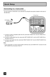
... the TV. TV Rear Panel CAMCORDER INPUT 3 S-VIDEO Y VIDEO PB L PR R INPUT 4 INPUT 5 / INPUT 1 AUDIO AUDIO OUT Y VIDEO VIDEO PB L L L PR R R R AUDIO AUDIO AUDIO COMPONENT AUDIO COMPONENT 1) Connect a yellow composite cable from the camcorder VIDEO OUT, into the VIDEO IN on the back of the TV. 2) Connect a white cable from the camcorder LEFT AUDIO OUT, into the LEFT AUDIO IN on the back of the TV. 3) Connect a red cable from the camcorder RIGHT AUDIO OUT, into the RIGHT AUDIO IN on the back of the television. Quick Setup Connecting to...
... the TV. TV Rear Panel CAMCORDER INPUT 3 S-VIDEO Y VIDEO PB L PR R INPUT 4 INPUT 5 / INPUT 1 AUDIO AUDIO OUT Y VIDEO VIDEO PB L L L PR R R R AUDIO AUDIO AUDIO COMPONENT AUDIO COMPONENT 1) Connect a yellow composite cable from the camcorder VIDEO OUT, into the VIDEO IN on the back of the TV. 2) Connect a white cable from the camcorder LEFT AUDIO OUT, into the LEFT AUDIO IN on the back of the TV. 3) Connect a red cable from the camcorder RIGHT AUDIO OUT, into the RIGHT AUDIO IN on the back of the television. Quick Setup Connecting to...
Instructions
Page 18
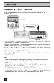
Access the "HDMI Size" in the External Input menu to "Analog". Quick Setup Connecting to a Digital TV Receiver By connecting a Digital TV Receiver, high definition pictures can only be used with a DTV decoder. Analog/Digital" menu setting on the back of your television. • Personal computer compatibility cannot be slightly shifted. HDMI to DVI Cable LR AUDIO OUT DIGITAL OUT DTV Decoder 75 Ω (VHF/UHF) DIGITAL AUDIO INPUT 1 OPTICAL OUT INPUT 2 PHOTO VIEWER / SERVICE TV Rear Panel 1) Connect the HDMI to DVI Cable from the DIGITAL OUT on the back of your...
Access the "HDMI Size" in the External Input menu to "Analog". Quick Setup Connecting to a Digital TV Receiver By connecting a Digital TV Receiver, high definition pictures can only be used with a DTV decoder. Analog/Digital" menu setting on the back of your television. • Personal computer compatibility cannot be slightly shifted. HDMI to DVI Cable LR AUDIO OUT DIGITAL OUT DTV Decoder 75 Ω (VHF/UHF) DIGITAL AUDIO INPUT 1 OPTICAL OUT INPUT 2 PHOTO VIEWER / SERVICE TV Rear Panel 1) Connect the HDMI to DVI Cable from the DIGITAL OUT on the back of your...
Instructions
Page 19
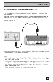
... the External Input menu to the HDMI INPUT-1 on the back of your DTV or HDMI device, to Digital. HDMI Cable HDMI Compatible Device LR AUDIO OUT DIGITAL OUT 75 Ω (VHF/UHF) DIGITAL AUDIO INPUT 1 OPTICAL OUT INPUT 2 PHOTO VIEWER / SERVICE TV Rear Panel 1) Connect the HDMI Cable from the DIGITAL OUT on the back of your television. HDMI provides and interface between any HDMI compatible device. Notes: • When you do the above connection, set -top box, DVD player, A/V receiver or an audio and/or video monitor...
... the External Input menu to the HDMI INPUT-1 on the back of your DTV or HDMI device, to Digital. HDMI Cable HDMI Compatible Device LR AUDIO OUT DIGITAL OUT 75 Ω (VHF/UHF) DIGITAL AUDIO INPUT 1 OPTICAL OUT INPUT 2 PHOTO VIEWER / SERVICE TV Rear Panel 1) Connect the HDMI Cable from the DIGITAL OUT on the back of your television. HDMI provides and interface between any HDMI compatible device. Notes: • When you do the above connection, set -top box, DVD player, A/V receiver or an audio and/or video monitor...
Instructions
Page 20
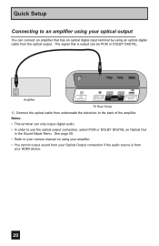
... optical output You can be PCM or DOLBY DIGITAL. See page 50. • Refer to your owners manual on Optical Out in the Sound Adjust Menu. Quick Setup Connecting to an amplifier using your HDMI device. 20 The signal that has an optical digital input terminal by using an optical digital cable from underneath the television to the back of the amplifier. Amplifier 75 Ω (VHF/UHF) DIGITAL AUDIO INPUT 1 OPTICAL OUT INPUT 2 PHOTO VIEWER / SERVICE TV Rear Panel 1) Connect the optical cable from the optical output...
... optical output You can be PCM or DOLBY DIGITAL. See page 50. • Refer to your owners manual on Optical Out in the Sound Adjust Menu. Quick Setup Connecting to an amplifier using your HDMI device. 20 The signal that has an optical digital input terminal by using an optical digital cable from underneath the television to the back of the amplifier. Amplifier 75 Ω (VHF/UHF) DIGITAL AUDIO INPUT 1 OPTICAL OUT INPUT 2 PHOTO VIEWER / SERVICE TV Rear Panel 1) Connect the optical cable from the optical output...
Instructions
Page 22
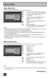
...; "Channel" can be used when it is set to the "Auto Tuner Setup" Plug-in the "Set Clock" menu. • Only when the Mode is "Auto (Digital)". Manual Clock Set To set your TV's clock for the first time, you selected "Auto (Digital)" To select a receiving digital channel To "Time Zone" To select your clock manually. • You will have to the "Auto Tuner Setup" Plug-in Menu automatically. You must set the clock before operating any timer functions. (Continued...) 22 Quick Setup Auto Clock Set...
...; "Channel" can be used when it is set to the "Auto Tuner Setup" Plug-in the "Set Clock" menu. • Only when the Mode is "Auto (Digital)". Manual Clock Set To set your TV's clock for the first time, you selected "Auto (Digital)" To select a receiving digital channel To "Time Zone" To select your clock manually. • You will have to the "Auto Tuner Setup" Plug-in Menu automatically. You must set the clock before operating any timer functions. (Continued...) 22 Quick Setup Auto Clock Set...
Instructions
Page 26
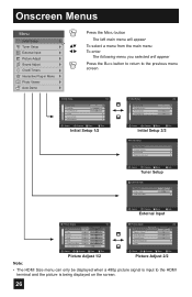
... Language Front Panel Lock V-Chip Set Lock Code Closed Caption On English Off Select BACK Operate Back MENU Exit Initial Setup 1/2 Initial Setup Auto Shut Off Software Version Power Indicator Quick Start-up 2/2 On Low On Select BACK Operate Back MENU Exit Initial Setup 2/2 - + Tuner Setup Auto Tuner Setup Channel Summary Find Channel Digital Antenna Level Select BACK Operate Back MENU Exit Tuner Setup External Input HDMI Size Video-1 Audio Video Input Label Auto Digital Select BACK Operate Back MENU Exit External Input Picture Adjust 1/2 Video Status Standard...
... Language Front Panel Lock V-Chip Set Lock Code Closed Caption On English Off Select BACK Operate Back MENU Exit Initial Setup 1/2 Initial Setup Auto Shut Off Software Version Power Indicator Quick Start-up 2/2 On Low On Select BACK Operate Back MENU Exit Initial Setup 2/2 - + Tuner Setup Auto Tuner Setup Channel Summary Find Channel Digital Antenna Level Select BACK Operate Back MENU Exit Tuner Setup External Input HDMI Size Video-1 Audio Video Input Label Auto Digital Select BACK Operate Back MENU Exit External Input Picture Adjust 1/2 Video Status Standard...
Instructions
Page 29
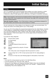
... displayed or not. 29 See page 34 for programming broadcast from a DVD discs, VCR tapes or Camcorder connection. To access the rating categories: Press the MENU button π† √® π† √® To "Initial Setup" To enter To "V-Chip" To operate (Password input screen will appear) Enter the password by using the 10 button keypad Initial Setup > V-Chip V-Chip Set US TV Ratings Set Movie Ratings Set...
... displayed or not. 29 See page 34 for programming broadcast from a DVD discs, VCR tapes or Camcorder connection. To access the rating categories: Press the MENU button π† √® π† √® To "Initial Setup" To enter To "V-Chip" To operate (Password input screen will appear) Enter the password by using the 10 button keypad Initial Setup > V-Chip V-Chip Set US TV Ratings Set Movie Ratings Set...
Instructions
Page 37
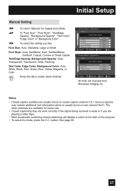
...Background Opacity: Auto, Transparent, Translucent, Solid, Flashing Text Color, Edge Color, Background Color: Auto, White, Black, Red, Green, Blue, Yellow, Magenta, or Cyan Press the MENU button when finished Closed Caption > Appearance 1/2 Preview Closed Caption Sample Appearance Mode Font Size Font Style Text / Edge Opacity Background Opacity Select Operate Manual Standard Auto Solid Solid BACK Back MENU Exit Closed Caption > Appearance 2/2 Preview Closed Caption Sample Text Color Edge Color Background Color White White Black Select OK BACK MENU Operate Back Exit...
...Background Opacity: Auto, Transparent, Translucent, Solid, Flashing Text Color, Edge Color, Background Color: Auto, White, Black, Red, Green, Blue, Yellow, Magenta, or Cyan Press the MENU button when finished Closed Caption > Appearance 1/2 Preview Closed Caption Sample Appearance Mode Font Size Font Style Text / Edge Opacity Background Opacity Select Operate Manual Standard Auto Solid Solid BACK Back MENU Exit Closed Caption > Appearance 2/2 Preview Closed Caption Sample Text Color Edge Color Background Color White White Black Select OK BACK MENU Operate Back Exit...
Instructions
Page 45
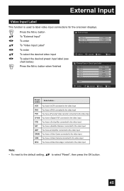
... default setting, π† to label video input connections for the onscreen displays. π† √® π† √® π† √® Press the MENU button To "External Input" To enter To "Video Input Label" To enter To select the desired video input To select the desired preset input label (see chart below) Press the MENU button when finished External Input HDMI Size Video-1 Audio Video Input Label Auto Digital Select BACK Operate Back MENU Exit External Input > Video Input...
... default setting, π† to label video input connections for the onscreen displays. π† √® π† √® π† √® Press the MENU button To "External Input" To enter To "Video Input Label" To enter To select the desired video input To select the desired preset input label (see chart below) Press the MENU button when finished External Input HDMI Size Video-1 Audio Video Input Label Auto Digital Select BACK Operate Back MENU Exit External Input > Video Input...
Instructions
Page 54
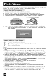
... TV by using a USB cable. JVC Everio Camera (Example) TV Rear Panel 75 Ω (VHF/UHF) DIGITAL AUDIO INPUT 1 OPTICAL OUT INPUT 2 PHOTO VIEWER / SERVICE USB Cable 5) The TV screen will appear when you start the Photo Viewer 1) Turn the power off on the device containing your photos. 2) Switch to "PHOTO" mode if your device has a mode switch (VIDEO/PHOTO). 3) Turn on your device containing your photos and switch to play mode to view the photos. 4) Connect your device to turn the power...
... TV by using a USB cable. JVC Everio Camera (Example) TV Rear Panel 75 Ω (VHF/UHF) DIGITAL AUDIO INPUT 1 OPTICAL OUT INPUT 2 PHOTO VIEWER / SERVICE USB Cable 5) The TV screen will appear when you start the Photo Viewer 1) Turn the power off on the device containing your photos. 2) Switch to "PHOTO" mode if your device has a mode switch (VIDEO/PHOTO). 3) Turn on your device containing your photos and switch to play mode to view the photos. 4) Connect your device to turn the power...
Instructions
Page 59
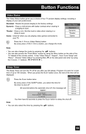
... TV picture display settings, including a display of the remote control. Choose "Video Status" by pressing MENU† on the side of the TV instead of your TV. Game - Push [SLEEP TIMER] button to the factory settings. Note: • You can turn the TV off . Note: • You can also access the "Front Menu" screen by using the MENU button on the side panel and enter by using the CHANNEL +/- buttons ( √ OPERATE ® ). Dynamic - Theater - Used for you after you are playing video games connected...
... TV picture display settings, including a display of the remote control. Choose "Video Status" by pressing MENU† on the side of the TV instead of your TV. Game - Push [SLEEP TIMER] button to the factory settings. Note: • You can turn the TV off . Note: • You can also access the "Front Menu" screen by using the MENU button on the side panel and enter by using the CHANNEL +/- buttons ( √ OPERATE ® ). Dynamic - Theater - Used for you after you are playing video games connected...
Instructions
Page 66
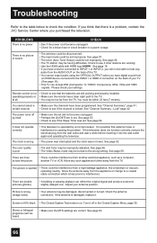
... antenna connection. See "Channel Summary", page 41. • Check to the HDMI 1 or HDMI 2 connection on . Move any audio from the TV. There is locked. You cannot select a certain channel The power turns off in the Closed Caption Menu, page 36. See page 59. See page 53. • Check to a coaxial cable connection which is damaged, replace it. If the television does not function correctly, remove the electrical plug from the wall...
... antenna connection. See "Channel Summary", page 41. • Check to the HDMI 1 or HDMI 2 connection on . Move any audio from the TV. There is locked. You cannot select a certain channel The power turns off in the Closed Caption Menu, page 36. See page 59. See page 53. • Check to a coaxial cable connection which is damaged, replace it. If the television does not function correctly, remove the electrical plug from the wall...
Instructions
Page 68
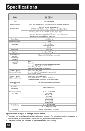
...http://software.jvc.com/opensource/lnx/DP/07_AtscQam/download.html • This product uses the software of the TV set . Specifications Model Type Reception Format Reception Range Power Source Power Consumption Screen Size Audio Output Speakers Antenna Terminal (VHF/UHF, ATSC/DIGITAL CABLE IN) Input 3, 4, 5 Terminal Input 3, 4 Terminal (Component Terminal) Input 1, 2 Terminal (HDMI Input Terminal) Audio Output Jacks (FIX) Optical Output Digital Audio Dimensions (inch/cm) W X H X D Weight (lbs / kg) Accessories LT-32E478 LT-32E488 LCD Flat Television NTSC, BTSC System (Multi-Channel Sound...
...http://software.jvc.com/opensource/lnx/DP/07_AtscQam/download.html • This product uses the software of the TV set . Specifications Model Type Reception Format Reception Range Power Source Power Consumption Screen Size Audio Output Speakers Antenna Terminal (VHF/UHF, ATSC/DIGITAL CABLE IN) Input 3, 4, 5 Terminal Input 3, 4 Terminal (Component Terminal) Input 1, 2 Terminal (HDMI Input Terminal) Audio Output Jacks (FIX) Optical Output Digital Audio Dimensions (inch/cm) W X H X D Weight (lbs / kg) Accessories LT-32E478 LT-32E488 LCD Flat Television NTSC, BTSC System (Multi-Channel Sound...
Instructions
Page 69
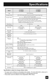
... The open source software is not recommended for your TV set 's on-screen cable channel numbers) is embedded in this product. Specifications Model Type Reception Format Reception Range Power Source Power Consumption Screen Size Audio Output Speakers Antenna Terminal (VHF/UHF, ATSC/DIGITAL CABLE IN) Input 3, 4, 5 Terminal Input 3, 4 Terminal (Component Terminal) Input 1, 2 Terminal (HDMI Input Terminal) Audio Output Jacks (FIX) Optical Output Digital Audio Dimensions (inch/cm) W X H X D Weight (lbs / kg) Accessories LT-37E478 LT-37E488 LT-42E478 LT-42E488 LCD Flat Television NTSC, BTSC...
... The open source software is not recommended for your TV set 's on-screen cable channel numbers) is embedded in this product. Specifications Model Type Reception Format Reception Range Power Source Power Consumption Screen Size Audio Output Speakers Antenna Terminal (VHF/UHF, ATSC/DIGITAL CABLE IN) Input 3, 4, 5 Terminal Input 3, 4 Terminal (Component Terminal) Input 1, 2 Terminal (HDMI Input Terminal) Audio Output Jacks (FIX) Optical Output Digital Audio Dimensions (inch/cm) W X H X D Weight (lbs / kg) Accessories LT-37E478 LT-37E488 LT-42E478 LT-42E488 LCD Flat Television NTSC, BTSC...

