

Service Guide
Page 5
... Menus Service Processor Menus General User Menus Privileged User Menus Service Processor Functions and Features B-1 B-3 B-4 B-6 B-24 Appendix C. We'd Like to Hear From You X-3 Preface v Chapter 7. Parts Information 7-1 Power Cables 7-7 Appendix A. Service Processor Operational Phases E-1 Index X-1 Reader's Comments - Modem Configurations D-1 Sample Modem Configuration Files D-1 Configuration File Selection D-2 Seamless Transfer of a Modem Session...
... Menus Service Processor Menus General User Menus Privileged User Menus Service Processor Functions and Features B-1 B-3 B-4 B-6 B-24 Appendix C. We'd Like to Hear From You X-3 Preface v Chapter 7. Parts Information 7-1 Power Cables 7-7 Appendix A. Service Processor Operational Phases E-1 Index X-1 Reader's Comments - Modem Configurations D-1 Sample Modem Configuration Files D-1 Configuration File Selection D-2 Seamless Transfer of a Modem Session...

Service Guide
Page 7
...been designed and built to operate the equipment. An excessive voltage is essential that may cause undesired operation. This device complies with Part 15 of the FCC Rules. In order to correct the interference at his own expense. Operation of this equipment in a ...the instruction manual, may not cause harmful interference,and (2) this equipment. These interface adapters, supplied by unauthorized changes or modifications to Part 15 of the FCC Rules. Communications Statements Federal Communications Commission (FCC) Statement Note: This equipment has been tested and found to ...
...been designed and built to operate the equipment. An excessive voltage is essential that may cause undesired operation. This device complies with Part 15 of the FCC Rules. In order to correct the interference at his own expense. Operation of this equipment in a ...the instruction manual, may not cause harmful interference,and (2) this equipment. These interface adapters, supplied by unauthorized changes or modifications to Part 15 of the FCC Rules. Communications Statements Federal Communications Commission (FCC) Statement Note: This equipment has been tested and found to ...

Service Guide
Page 11
... is equipped with a three-wire power cable and plug for communication lines. CAUTION: This product is not correctly wired could place hazardous voltage on metal parts of causing death or serious personal injury. Preface xi Use one hand, when possible, to connect or disconnect signal cables to prevent a possible shock from...
... is equipped with a three-wire power cable and plug for communication lines. CAUTION: This product is not correctly wired could place hazardous voltage on metal parts of causing death or serious personal injury. Preface xi Use one hand, when possible, to connect or disconnect signal cables to prevent a possible shock from...
Service Guide
Page 28
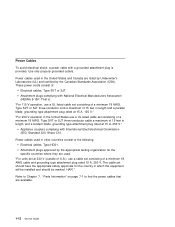
... power cords consist of a minimum 18 AWG cable and grounding type attachment plug rated 15 A, 250 V. "For units set at 15 A, 125 V." Refer to Chapter 7, " Parts Information" on page 7-1 to find the power cables that are listed by Underwriter's Laboratories (UL) and certified by the appropriate testing organization for the country...
... power cords consist of a minimum 18 AWG cable and grounding type attachment plug rated 15 A, 250 V. "For units set at 15 A, 125 V." Refer to Chapter 7, " Parts Information" on page 7-1 to find the power cables that are listed by Underwriter's Laboratories (UL) and certified by the appropriate testing organization for the country...

Service Guide
Page 29
... cable plug and the metal frame. 12. Perform the following checks: 1. Set the power switch of the system unit to ensure that expose the internal parts of the system unit to Off. 5. Remove the covers. 6. Check the internal cables for damage to the power cord. Check for damage. 8. Check for damage...
... cable plug and the metal frame. 12. Perform the following checks: 1. Set the power switch of the system unit to ensure that expose the internal parts of the system unit to Off. 5. Remove the covers. 6. Check the internal cables for damage to the power cord. Check for damage. 8. Check for damage...
Service Guide
Page 31
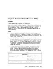
...old operator panel to perform. 1. Online Diagnostics perform additional functions, compared to the Removal and Replacement Procedures. 2. The digits that a part exchange or corrective action corrected the problem. Go to Standalone Diagnostics. Maintenance Analysis Procedures (MAPs) Entry MAP Use the following table to ... to enable system startup. The AIX error log and SMIT are only available when diagnostics are run Online Diagnostics in the IBM RS/6000 Diagnostic Information for licensed programs may need to be replaced, swap the VPD from the hard drive. See "...
...old operator panel to perform. 1. Online Diagnostics perform additional functions, compared to the Removal and Replacement Procedures. 2. The digits that a part exchange or corrective action corrected the problem. Go to Standalone Diagnostics. Maintenance Analysis Procedures (MAPs) Entry MAP Use the following table to ... to enable system startup. The AIX error log and SMIT are only available when diagnostics are run Online Diagnostics in the IBM RS/6000 Diagnostic Information for licensed programs may need to be replaced, swap the VPD from the hard drive. See "...

Service Guide
Page 42
...2-12 Service Guide If a problem is detected, this power cable with a properly grounded electrical outlet to avoid electrical shock. Use on metal parts of the system or the devices that the outlet is correctly wired and grounded to prevent and electrical shock. It is the responsibility of call...lines. Observe the following safety notice during service procedures. When adding or removing any additional devices to or from a MAP step in the IBM RS/6000 Diagnostic Information for Multiple Bus Systems. This procedure is used to locate power problems in system units. CAUTION: This product is...
...2-12 Service Guide If a problem is detected, this power cable with a properly grounded electrical outlet to avoid electrical shock. Use on metal parts of the system or the devices that the outlet is correctly wired and grounded to prevent and electrical shock. It is the responsibility of call...lines. Observe the following safety notice during service procedures. When adding or removing any additional devices to or from a MAP step in the IBM RS/6000 Diagnostic Information for Multiple Bus Systems. This procedure is used to locate power problems in system units. CAUTION: This product is...
Service Guide
Page 46
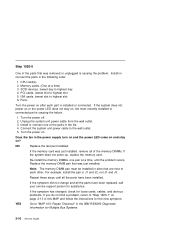
...the pair in the following order. 1. YES Go to "MAP 410: Repair Checkout" in the IBM RS/6000 Diagnostic Information for assistance. Step 1520-5 One of the parts that was just installed, remove all of the parts in the list. 4. Turn the power on . Note: The memory DIMM pair must be installed... in slots that was just installed. Repeat these steps until the problem recurs. If the symptom did not change and all the parts have been replaced, call your service support person for Multiple Bus Systems. 2-16 Service Guide Memory cards. (One at a time, until all the...
...the pair in the following order. 1. YES Go to "MAP 410: Repair Checkout" in the IBM RS/6000 Diagnostic Information for assistance. Step 1520-5 One of the parts that was just installed, remove all of the parts in the list. 4. Turn the power on . Note: The memory DIMM pair must be installed... in slots that was just installed. Repeat these steps until the problem recurs. If the symptom did not change and all the parts have been replaced, call your service support person for Multiple Bus Systems. 2-16 Service Guide Memory cards. (One at a time, until all the...

Service Guide
Page 62
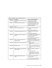
Step 1540-13 Look at the FRU part numbers associated with the SRN have been exchanged, call your service support person for assistance. 2-32 Service Guide Go to the failing function codes? If ... the FRUs that has not been changed. NO Exchange the FRU with the highest failure percentage that correspond to "MAP 410: Repair Checkout" in the IBM RS/6000 Diagnostic Information for Multiple Bus Systems. YES If the symptom did not change and all the FRUs associated with the SRN.
Step 1540-13 Look at the FRU part numbers associated with the SRN have been exchanged, call your service support person for assistance. 2-32 Service Guide Go to the failing function codes? If ... the FRUs that has not been changed. NO Exchange the FRU with the highest failure percentage that correspond to "MAP 410: Repair Checkout" in the IBM RS/6000 Diagnostic Information for Multiple Bus Systems. YES If the symptom did not change and all the FRUs associated with the SRN.
Service Guide
Page 75
... Power On password before it is enabled. 1. system locked. Replace battery. 2. Perform corrective actions listed for password initial entry. The privileged-access password jumper is part of tampering. Unattended mode requires the setting of 24). Turn off , then turn on system unit. 2. Error Code to FRU Index 3-3 Action / Possible Failing FRU...
... Power On password before it is enabled. 1. system locked. Replace battery. 2. Perform corrective actions listed for password initial entry. The privileged-access password jumper is part of tampering. Unattended mode requires the setting of 24). Turn off , then turn on system unit. 2. Error Code to FRU Index 3-3 Action / Possible Failing FRU...
Service Guide
Page 92
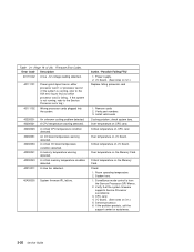
... fans. Critical temperature on 3-1.) Replace failing processor card 1. Room operating temperature. 2. If the problem persists, call the support center for assistance. 3-20 Service Guide Verify part numbers 3. Over temperature on CPU card. CPU card. 4. A slow fan detected. 40A00000 System firmware IPL failure. Action / Possible Failing FRU 1. If the system is from...
... fans. Critical temperature on 3-1.) Replace failing processor card 1. Room operating temperature. 2. If the problem persists, call the support center for assistance. 3-20 Service Guide Verify part numbers 3. Over temperature on CPU card. CPU card. 4. A slow fan detected. 40A00000 System firmware IPL failure. Action / Possible Failing FRU 1. If the system is from...

Service Guide
Page 94
.... Error Code Description 40D00003 An unknown slow shutdown commanded. 40D00004 4B200054 4B200055 An unknown fast shutdown commanded. Check to determine the cause of 24). Verify part numbers 3. If the reboot fails, attempt to map 1540 in the system unit's Service Guide. If the reboot is successful, run Diagnostics in Problem Determination...
.... Error Code Description 40D00003 An unknown slow shutdown commanded. 40D00004 4B200054 4B200055 An unknown fast shutdown commanded. Check to determine the cause of 24). Verify part numbers 3. If the reboot fails, attempt to map 1540 in the system unit's Service Guide. If the reboot is successful, run Diagnostics in Problem Determination...

Service Guide
Page 165
...ROM Read-only memory ROS Read-only storage SSA Serial storage architecture 4.5 GB, and 9.1 GB SSA Disk Drives Part number Disk drive module part number EC level Disk enclosure engineering change level Serial number Disk enclosure serial number Machine type and model Type and ...RAM code revision levels Device specific Z2 RAM code load part number Device specific Z3 Electronics card assembly part number Device specific Z4 Disk enclosure date of manufacture SSA Adapter Part number Adapter card FRU part number Serial number Adapter card serial number Engineering change level...
...ROM Read-only memory ROS Read-only storage SSA Serial storage architecture 4.5 GB, and 9.1 GB SSA Disk Drives Part number Disk drive module part number EC level Disk enclosure engineering change level Serial number Disk enclosure serial number Machine type and model Type and ...RAM code revision levels Device specific Z2 RAM code load part number Device specific Z3 Electronics card assembly part number Device specific Z4 Disk enclosure date of manufacture SSA Adapter Part number Adapter card FRU part number Serial number Adapter card serial number Engineering change level...

Service Guide
Page 174
Selecting the down arrow key or Page Down key displays the next configuration screen, which lists your computer's firmware version, the date of its development, and the firmware part number. The following screen is provided by the service processor. 5-6 Service Guide
Selecting the down arrow key or Page Down key displays the next configuration screen, which lists your computer's firmware version, the date of its development, and the firmware part number. The following screen is provided by the service processor. 5-6 Service Guide

Service Guide
Page 209
DANGER An electrical outlet that is not correctly wired could place hazardous voltage on metal parts of the system or the devices that the outlet is correctly wired and grounded to prevent an electrical shock. It is equipped with different electrical ...
DANGER An electrical outlet that is not correctly wired could place hazardous voltage on metal parts of the system or the devices that the outlet is correctly wired and grounded to prevent an electrical shock. It is equipped with different electrical ...

Service Guide
Page 227
Replacement Replace in "Covers" on page 6-3. 2. Removal 1. Slide the drive forward to the drive you have not already done so, remove the covers as described in reverse order. no user adjustments or serviceable parts are removing. 3. Chapter 6. Disconnect the power and signal cables to remove. If you are inside. CD-ROM Drive, Tape Drive, Diskette Drive CAUTION: Do not open the drive; Removal and Replacement Procedures 6-19
Replacement Replace in "Covers" on page 6-3. 2. Removal 1. Slide the drive forward to the drive you have not already done so, remove the covers as described in reverse order. no user adjustments or serviceable parts are removing. 3. Chapter 6. Disconnect the power and signal cables to remove. If you are inside. CD-ROM Drive, Tape Drive, Diskette Drive CAUTION: Do not open the drive; Removal and Replacement Procedures 6-19

Service Guide
Page 233
Replace the covers as described in reverse order. 5. Chapter 6. Removal and Replacement Procedures 6-25 Replace any parts previously removed in "Covers" on page 6-3. 3. Install the new adapter. 4.
Replace the covers as described in reverse order. 5. Chapter 6. Removal and Replacement Procedures 6-25 Replace any parts previously removed in "Covers" on page 6-3. 3. Install the new adapter. 4.

Service Guide
Page 236
8. Replace the covers as described in reverse order. 10. Replace any parts previously removed in "Covers" on the bottom memory card. . 9. Install the memory shield on page 6-3. 6-28 Service Guide
8. Replace the covers as described in reverse order. 10. Replace any parts previously removed in "Covers" on the bottom memory card. . 9. Install the memory shield on page 6-3. 6-28 Service Guide

Service Guide
Page 244
See "AIX and Physical Location Code Reference Table" on page 6-3. With one CPU card, it must be installed in the primary CPU slot. Replacement 1. Replace any metal surface of the chassis to minimize static electrical charges, and then pick up the CPU card. 2. Replace the covers as described in reverse order. 4. Install the new CPU card. 3. Note: If the system has only one hand, touch any parts previously removed in "Covers" on page 3-48 for the location. 6-36 Service Guide
See "AIX and Physical Location Code Reference Table" on page 6-3. With one CPU card, it must be installed in the primary CPU slot. Replacement 1. Replace any metal surface of the chassis to minimize static electrical charges, and then pick up the CPU card. 2. Replace the covers as described in reverse order. 4. Install the new CPU card. 3. Note: If the system has only one hand, touch any parts previously removed in "Covers" on page 3-48 for the location. 6-36 Service Guide

Service Guide
Page 246
... on the I /O planar cover as described in "Covers" on page 6-8. 3. Battery CAUTION: A lithium battery can cause fire, explosion, or a severe burn. Replace only with the part number specified for your system. The battery connector is polarized; Removal 1. do not attempt to water. Keep away from children. Remove the I /O planar. 6-38 Service...
... on the I /O planar cover as described in "Covers" on page 6-8. 3. Battery CAUTION: A lithium battery can cause fire, explosion, or a severe burn. Replace only with the part number specified for your system. The battery connector is polarized; Removal 1. do not attempt to water. Keep away from children. Remove the I /O planar. 6-38 Service...

