
Service Guide
Page 3
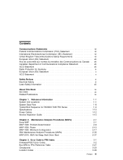
... (MAPs 2-1 Entry MAP 2-1 MAP 1020: Problem Determination 2-6 MAP 1520: Power 2-12 MAP 1540: Minimum Configuration 2-17 SSA Maintenance Analysis Procedures (MAPs 2-35 MAP 2010: SSA Hot-Swap Disk Drive-Start 2-37 Chapter 3. Error Code to FRU Index 3-1 Firmware/POST Error Codes 3-2 Bus SRN ...
... (MAPs 2-1 Entry MAP 2-1 MAP 1020: Problem Determination 2-6 MAP 1520: Power 2-12 MAP 1540: Minimum Configuration 2-17 SSA Maintenance Analysis Procedures (MAPs 2-35 MAP 2010: SSA Hot-Swap Disk Drive-Start 2-37 Chapter 3. Error Code to FRU Index 3-1 Firmware/POST Error Codes 3-2 Bus SRN ...
Service Guide
Page 4
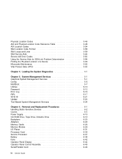
... and Links SSA Service Aids Service Aid Error Codes Using the Service Aids for SSA-Link Problem Determination Finding the Physical Location of a Device Microcode Maintenance Vital Product Data (VPD 3-46 3-48 3-54 3-58 3-59 3-64 3-83 3-84 3-90 3-92 3-93 Chapter 4. Removal and Replacement Procedures 6-1 Handling Static-Sensitive Devices 6-2 Covers...
... and Links SSA Service Aids Service Aid Error Codes Using the Service Aids for SSA-Link Problem Determination Finding the Physical Location of a Device Microcode Maintenance Vital Product Data (VPD 3-46 3-48 3-54 3-58 3-59 3-64 3-83 3-84 3-90 3-92 3-93 Chapter 4. Removal and Replacement Procedures 6-1 Handling Static-Sensitive Devices 6-2 Covers...

Service Guide
Page 13
... to the requirements of enclosures, electronics, and redundant interlocks such that there is no exposure to laser radiation above a Class 1 level during normal operation, user maintenance, or servicing conditions. Do not attempt to operate the drive while it is not serviceable and is to the requirements of the Department of Health...
... to the requirements of enclosures, electronics, and redundant interlocks such that there is no exposure to laser radiation above a Class 1 level during normal operation, user maintenance, or servicing conditions. Do not attempt to operate the drive while it is not serviceable and is to the requirements of the Department of Health...

Service Guide
Page 15
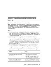
...Information contains information to help users set up, install options, configure, modify, and solve minor problems. The IBM RS/6000 Diagnostic Information for purchase: The IBM RS/6000 7025 F50 Series User's Guide contains information to help you plan your installation. This manual is ..., error codes, service request numbers, and failing function codes. About This Book This book provides maintenance information that is specific to repair system failures. It also contains Maintenance Analysis Procedures (MAPs) that are not common to other systems. MAPs that the service technician has...
...Information contains information to help users set up, install options, configure, modify, and solve minor problems. The IBM RS/6000 Diagnostic Information for purchase: The IBM RS/6000 7025 F50 Series User's Guide contains information to help you plan your installation. This manual is ..., error codes, service request numbers, and failing function codes. About This Book This book provides maintenance information that is specific to repair system failures. It also contains Maintenance Analysis Procedures (MAPs) that are not common to other systems. MAPs that the service technician has...

Service Guide
Page 29
... the covers for dirt, water, and any unsafe condition is the responsibility of the owner of the system unit to the system unit, check for a maintenance agreement. They should be corrected before anyone can service the machine. Check for proper fit to the power cord. Note: The correction of the system...
... the covers for dirt, water, and any unsafe condition is the responsibility of the owner of the system unit to the system unit, check for a maintenance agreement. They should be corrected before anyone can service the machine. Check for proper fit to the power cord. Note: The correction of the system...
Service Guide
Page 31
.... Go to determine your use only the first eight digits to verify that new keys for your starting point. Maintenance Analysis Procedures 2-1 Maintenance Analysis Procedures (MAPs) Entry MAP Use the following table to the Removal and Replacement Procedures. 2. See "Location ...Codes" on the operator panel control assembly (connector U2). The AIX error log and SMIT are only available when diagnostics are run Online Diagnostics in the IBM...
.... Go to determine your use only the first eight digits to verify that new keys for your starting point. Maintenance Analysis Procedures 2-1 Maintenance Analysis Procedures (MAPs) Entry MAP Use the following table to the Removal and Replacement Procedures. 2. See "Location ...Codes" on the operator panel control assembly (connector U2). The AIX error log and SMIT are only available when diagnostics are run Online Diagnostics in the IBM...

Service Guide
Page 33
...All display problems. 888 is connected to S1. If entering the password from the keyboard which is displayed when booting in the IBM RS/6000 Diagnostic Information for the terminal. If the problem is attached to the system, replace the keyboard. Symptom The system does..."MAP 1540: Minimum Configuration" on 2-1.) 2. Action Verify that the ASCII terminal is displayed in the control panel followed by additional error codes. Maintenance Analysis Procedures 2-3 If replacing the keyboard does not fix the problem, replace the I /O planar if these procedures do not find a problem ...
...All display problems. 888 is connected to S1. If entering the password from the keyboard which is displayed when booting in the IBM RS/6000 Diagnostic Information for the terminal. If the problem is attached to the system, replace the keyboard. Symptom The system does..."MAP 1540: Minimum Configuration" on 2-1.) 2. Action Verify that the ASCII terminal is displayed in the control panel followed by additional error codes. Maintenance Analysis Procedures 2-3 If replacing the keyboard does not fix the problem, replace the I /O planar if these procedures do not find a problem ...

Service Guide
Page 35
Maintenance Analysis Procedures 2-5 Symptom You suspect a cable problem. Chapter 2. Action See the IBM RS/6000 Adapter, Device, and Cable Information for Multiple Bus Systems. All other problems. You Cannot Find the Symptom in this Table Go to "MAP 1020: Problem Determination" on page 2-6.
Maintenance Analysis Procedures 2-5 Symptom You suspect a cable problem. Chapter 2. Action See the IBM RS/6000 Adapter, Device, and Cable Information for Multiple Bus Systems. All other problems. You Cannot Find the Symptom in this Table Go to "MAP 1020: Problem Determination" on page 2-6.
Service Guide
Page 37
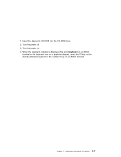
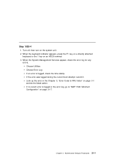
Turn the power on an ASCII terminal. Maintenance Analysis Procedures 2-7 Turn the power off. 3. When the keyboard indicator is displayed (the word keyboard on an ASCII terminal or the keyboard icon on a graphical display), press the F5 key on the directly-attached keyboard or the number 5 key on . 4. Insert the diagnostic CD-ROM into the CD-ROM drive. 2. Chapter 2. 1.
Turn the power on an ASCII terminal. Maintenance Analysis Procedures 2-7 Turn the power off. 3. When the keyboard indicator is displayed (the word keyboard on an ASCII terminal or the keyboard icon on a graphical display), press the F5 key on the directly-attached keyboard or the number 5 key on . 4. Insert the diagnostic CD-ROM into the CD-ROM drive. 2. Chapter 2. 1.

Service Guide
Page 39
... "E0xx" then go to "Checkpoints" on page 3-29. If you were directed here from the Entry MAP, go to the Fast Path MAP in the IBM RS/6000 Diagnostic Information for Multiple Bus Systems. Note: If the operator panel displays 2 sets of numbers, use the bottom set of the four-digit... number displayed in the operator panel, then go to "MAP 1540: Minimum Configuration" on page 2-17. Maintenance Analysis Procedures 2-9 Otherwise, find the symptom in the "Entry MAP" on page 2-1. All other numbers record SRN 101-xxx, where xxx is displayed in the...
... "E0xx" then go to "Checkpoints" on page 3-29. If you were directed here from the Entry MAP, go to the Fast Path MAP in the IBM RS/6000 Diagnostic Information for Multiple Bus Systems. Note: If the operator panel displays 2 sets of numbers, use the bottom set of the four-digit... number displayed in the operator panel, then go to "MAP 1540: Minimum Configuration" on page 2-17. Maintenance Analysis Procedures 2-9 Otherwise, find the symptom in the "Entry MAP" on page 2-1. All other numbers record SRN 101-xxx, where xxx is displayed in the...
Service Guide
Page 41
... key on a directly attached keyboard or the 1 key on the system unit. 2. Chapter 2. If the error was logged during the current boot attempt, record it. Maintenance Analysis Procedures 2-11 Choose Utilities Choose Error Log If an error is logged in the Chapter 3, "Error Code to "MAP 1540: Minimum Configuration" on page...
... key on a directly attached keyboard or the 1 key on the system unit. 2. Chapter 2. If the error was logged during the current boot attempt, record it. Maintenance Analysis Procedures 2-11 Choose Utilities Choose Error Log If an error is logged in the Chapter 3, "Error Code to "MAP 1540: Minimum Configuration" on page...

Service Guide
Page 43
NO Go to "Step 1520-3" on page 2-14. There is no indication of the fans, including the fan in the IBM RS/6000 Diagnostic Information for several reasons: 1. Turn the power off. 2. Check that the power outlet has been wired correctly with the correct voltage. 4. Check ...that the external power cable is pressed. Did you find a problem? Step 1520-1 You may be directed to this MAP for Multiple Bus Systems. Chapter 2. Maintenance Analysis Procedures 2-13 When the start /stop switch is pressed, the system begins to power on, but the power LED does not stay on. Go...
NO Go to "Step 1520-3" on page 2-14. There is no indication of the fans, including the fan in the IBM RS/6000 Diagnostic Information for several reasons: 1. Turn the power off. 2. Check that the power outlet has been wired correctly with the correct voltage. 4. Check ...that the external power cable is pressed. Did you find a problem? Step 1520-1 You may be directed to this MAP for Multiple Bus Systems. Chapter 2. Maintenance Analysis Procedures 2-13 When the start /stop switch is pressed, the system begins to power on, but the power LED does not stay on. Go...

Service Guide
Page 45
...stay on? NO Replace the I/O planar. Chapter 2. Remove all the ISA and PCI adapters. Connect the system unit power cable to the adapters. Maintenance Analysis Procedures 2-15 Unplug the system unit power cable from all the adapters. 4. Record the slot numbers of any cables attached to the wall ...outlet. 9. Turn the power off. 2. Remove the CPU card(s). 6. Go to "MAP 410: Repair Checkout" in the IBM RS/6000 Diagnostic Information for Multiple Bus Systems. YES Go to "Step 1520-5" on . Step 1520-4 1. Remove all the SCSI devices. 7.
...stay on? NO Replace the I/O planar. Chapter 2. Remove all the ISA and PCI adapters. Connect the system unit power cable to the adapters. Maintenance Analysis Procedures 2-15 Unplug the system unit power cable from all the adapters. 4. Record the slot numbers of any cables attached to the wall ...outlet. 9. Turn the power off. 2. Remove the CPU card(s). 6. Go to "MAP 410: Repair Checkout" in the IBM RS/6000 Diagnostic Information for Multiple Bus Systems. YES Go to "Step 1520-5" on . Step 1520-4 1. Remove all the SCSI devices. 7.
Service Guide
Page 47
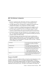
... service the system. MAP 1540: Minimum Configuration Notes: 1. It is a good idea to examine that a CD-ROM drive is installed and connected to attempt recoveries. Maintenance Analysis Procedures 2-17 From the System Power Control Menu go to unplug the power cable before proceeding (see Service Processor System Information Menu). 6. The Service...
... service the system. MAP 1540: Minimum Configuration Notes: 1. It is a good idea to examine that a CD-ROM drive is installed and connected to attempt recoveries. Maintenance Analysis Procedures 2-17 From the System Power Control Menu go to unplug the power cable before proceeding (see Service Processor System Information Menu). 6. The Service...

Service Guide
Page 49
... CPU cable is installed.] 8. Disconnect the SCSI cable from the first Memory card. Does the operator panel stabilize with the instructions on step 6 on . 15. Maintenance Analysis Procedures 2-19 Chapter 2. Plug in the power cable (and wait for the operator panel to assure stability, depending on the operator panel display). 14...
... CPU cable is installed.] 8. Disconnect the SCSI cable from the first Memory card. Does the operator panel stabilize with the instructions on step 6 on . 15. Maintenance Analysis Procedures 2-19 Chapter 2. Plug in the power cable (and wait for the operator panel to assure stability, depending on the operator panel display). 14...

Service Guide
Page 51
...-5" on system configuration. Note: Checkpoints E1F2, E1F3 and STBY are installed and tested, record the positions of memory DIMMs. 3. NO Go to stabilize at a checkpoint. Maintenance Analysis Procedures 2-21 Turn the power off and remove the power cable. 2. Repeat this configuration. 1. Chapter 2. Install a pair of the memory DIMMs in the second...
...-5" on system configuration. Note: Checkpoints E1F2, E1F3 and STBY are installed and tested, record the positions of memory DIMMs. 3. NO Go to stabilize at a checkpoint. Maintenance Analysis Procedures 2-21 Turn the power off and remove the power cable. 2. Repeat this configuration. 1. Chapter 2. Install a pair of the memory DIMMs in the second...

Service Guide
Page 53
a. Power supply. 3. Maintenance Analysis Procedures 2-23 I/O planar (See notes on . 5. Note: Checkpoints E1F2, E1F3 and STBY are stable as soon as they appear. Other checkpoints may take up ... MAP, and follow the instructions for the operator panel to assure stability, depending on system configuration. YES Go to "MAP 410: Repair Checkout" in the IBM RS/6000 Diagnostic Information for assistance. System card c. NO Reinstall the original FRU. If the symptom did not change and all the FRUs have been...
a. Power supply. 3. Maintenance Analysis Procedures 2-23 I/O planar (See notes on . 5. Note: Checkpoints E1F2, E1F3 and STBY are stable as soon as they appear. Other checkpoints may take up ... MAP, and follow the instructions for the operator panel to assure stability, depending on system configuration. YES Go to "MAP 410: Repair Checkout" in the IBM RS/6000 Diagnostic Information for assistance. System card c. NO Reinstall the original FRU. If the symptom did not change and all the FRUs have been...

Service Guide
Page 55
... remaining in the system unit is identified or all the FRUs have been exchanged. Graphics adapter (if installed). 3. I/O planar. (see notes on page 2-26. Chapter 2. Maintenance Analysis Procedures 2-25 If a problem is found, follow the instructions for the device attached to the S1 serial port or the display attached to the...
... remaining in the system unit is identified or all the FRUs have been exchanged. Graphics adapter (if installed). 3. I/O planar. (see notes on page 2-26. Chapter 2. Maintenance Analysis Procedures 2-25 If a problem is found, follow the instructions for the device attached to the S1 serial port or the display attached to the...

Service Guide
Page 57
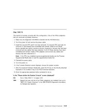
... of the FRUs remaining in this step until all the FRUs have been exchanged. Processor card 6. Repeat this MAP and follow the instructions for assistance. Maintenance Analysis Procedures 2-27 The graphics adapter, if the system console is defined as a graphical display. 4. Is the "Please define the System Console" screen displayed...
... of the FRUs remaining in this step until all the FRUs have been exchanged. Processor card 6. Repeat this MAP and follow the instructions for assistance. Maintenance Analysis Procedures 2-27 The graphics adapter, if the system console is defined as a graphical display. 4. Is the "Please define the System Console" screen displayed...
Service Guide
Page 59
...power off and remove the power cable. 3. If the Console Selection screen displays, choose the system console. 7. NO Go to do so. Maintenance Analysis Procedures 2-29 One of the FRUs (adapters) are installed, then go to load the supplemental media first. 4. If all of the ...FRUs (adapters) that you installed requires supplemental media use the Process Supplemental Media task to "MAP 410: Repair Checkout" in the IBM RS/6000 Diagnostic Information for Multiple Bus Systems. Chapter 2. Note: If the FRU you removed is probably defective, 1. Reinstall the power cable....
...power off and remove the power cable. 3. If the Console Selection screen displays, choose the system console. 7. NO Go to do so. Maintenance Analysis Procedures 2-29 One of the FRUs (adapters) are installed, then go to load the supplemental media first. 4. If all of the ...FRUs (adapters) that you installed requires supplemental media use the Process Supplemental Media task to "MAP 410: Repair Checkout" in the IBM RS/6000 Diagnostic Information for Multiple Bus Systems. Chapter 2. Note: If the FRU you removed is probably defective, 1. Reinstall the power cable....
