

Service Guide
Page 54
... unit. This triggers the SMS. 6. If the ASCII terminal or graphics display (including display adapter) are connected differently than before, the Console Selection screen appears and requires that a new console be selected. 5. If... an ASCII terminal has been defined as the system console, install the display adapter and connect the display to the I/O planar. Plug the keyboard into the keyboard connector on the rear of the ...is displayed or the system appears to do so. 7. Also connect the internal serial and Ethernet cables to it. Turn the power off. 2.
... unit. This triggers the SMS. 6. If the ASCII terminal or graphics display (including display adapter) are connected differently than before, the Console Selection screen appears and requires that a new console be selected. 5. If... an ASCII terminal has been defined as the system console, install the display adapter and connect the display to the I/O planar. Plug the keyboard into the keyboard connector on the rear of the ...is displayed or the system appears to do so. 7. Also connect the internal serial and Ethernet cables to it. Turn the power off. 2.

Service Guide
Page 107
... PCI bridge secondary bus E156 E15A E15B E15C E15D E15E E15F E160 E161 E162 E164 E168 E16C E16D E16E E16F E170 E171 E174 Create PCI ethernet node Create 64 bit host (primary) PCI controller node Transferring control to FRU Index 3-35 GTX100P Planar not detected or failed diagnostics. GTX100P Close Subsystem... on 3-29. See the note on 3-29. PCI Adapters 2. I \O board is replaced, see 3-1. Table 3-5 (Page 4 of PCI Bus Probe Executing PCI-Delay function Establish host connection Action/ Possible Failing FRU 1. See the note on 3-29.
... PCI bridge secondary bus E156 E15A E15B E15C E15D E15E E15F E160 E161 E162 E164 E168 E16C E16D E16E E16F E170 E171 E174 Create PCI ethernet node Create 64 bit host (primary) PCI controller node Transferring control to FRU Index 3-35 GTX100P Planar not detected or failed diagnostics. GTX100P Close Subsystem... on 3-29. See the note on 3-29. PCI Adapters 2. I \O board is replaced, see 3-1. Table 3-5 (Page 4 of PCI Bus Probe Executing PCI-Delay function Establish host connection Action/ Possible Failing FRU 1. See the note on 3-29.

Service Guide
Page 117
i. Replace I /O Board) h. Power Off then On and retry the boot operation b. Verify the network connection (network could be down) c. If this is successful, run the diagnostics against the system. Chapter 3. Replace network adapter (unless trying to boot using the ethernet controller on the I /O Board. (See notes on 3-1.) 4. Remove all installed adapters except the...
i. Replace I /O Board) h. Power Off then On and retry the boot operation b. Verify the network connection (network could be down) c. If this is successful, run the diagnostics against the system. Chapter 3. Replace network adapter (unless trying to boot using the ethernet controller on the I /O Board. (See notes on 3-1.) 4. Remove all installed adapters except the...
Service Guide
Page 123
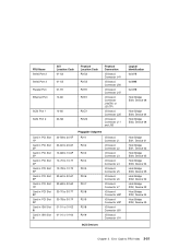
...-67 30-68 to 30-6F 30-70 to 30-77 30-78 to FRU Index 3-51 FRU Name Serial Port 2 Serial Port 3 Parallel Port Ethernet Port SCSI Port 1 SCSI Port 2 Card in PCI Slot 1P Card in PCI Slot 2P Card in PCI Slot 3P Card in PCI Slot 4P...-S3 01-R1 10-80 10-60 30-58 Physical Location Code P2/S2 P2/S3 P2/R1 P2/E1 P2/Z1 P2/Z2 Physical Connection I/O board Connector J41 I/O board Connector J50 I/O board Connector J47 I/O board Connector J18(TH) or J21(TP) I/O board Connector J25 I /O board Connector J91 SCSI Devices Logical...
...-67 30-68 to 30-6F 30-70 to 30-77 30-78 to FRU Index 3-51 FRU Name Serial Port 2 Serial Port 3 Parallel Port Ethernet Port SCSI Port 1 SCSI Port 2 Card in PCI Slot 1P Card in PCI Slot 2P Card in PCI Slot 3P Card in PCI Slot 4P...-S3 01-R1 10-80 10-60 30-58 Physical Location Code P2/S2 P2/S3 P2/R1 P2/E1 P2/Z1 P2/Z2 Physical Connection I/O board Connector J41 I/O board Connector J50 I/O board Connector J47 I/O board Connector J18(TH) or J21(TP) I/O board Connector J25 I /O board Connector J91 SCSI Devices Logical...

Service Guide
Page 204
After selecting the Ping option, you to test a connection to change how the Ethernet adapter communicates with the remote system. Token Ring (Slot=3) ===> 5-36 Service Guide No | | 3. Interface 1. Auto | Ping, the last option available from the Network Parameters menu, allows you must choose which adapter communicates with the network: | Full Duplex | | 1. Yes | | 2. Ethernet (Integrated) 2. Selecting the Full Duplex option allows you to a remote system unit.
After selecting the Ping option, you to test a connection to change how the Ethernet adapter communicates with the remote system. Token Ring (Slot=3) ===> 5-36 Service Guide No | | 3. Interface 1. Auto | Ping, the last option available from the Network Parameters menu, allows you must choose which adapter communicates with the network: | Full Duplex | | 1. Yes | | 2. Ethernet (Integrated) 2. Selecting the Full Duplex option allows you to a remote system unit.


