
User Manual
Page 2
... Operation 10 Setup Menu 12 Input Menu 13 Image Menu 14 Options Menu 15 No Signal Menu 16 MAINTENANCE 17 Lamp 17 Air Filter 19 Other Maintenance 19 Page TROUBLESHOOTING 20 OSD Message 20 Indicators Message 21 Symptom 22 SPECIFICATIONS 23 WARRANTY AND AFTER-SERVICE ......24 TABLES Table 1. CONTENTS Page FEATURES 2 BEFORE USE 2 Contents of Package 2 Part Names 3 Loading the Batteries 5 Fixing the Handle 5 INSTALLATION 6 Installation of the Projector and Screen........6 Angle Adjustment 6 Cabling 7 Power Connection 8 Example of the Video Electronics...
... Operation 10 Setup Menu 12 Input Menu 13 Image Menu 14 Options Menu 15 No Signal Menu 16 MAINTENANCE 17 Lamp 17 Air Filter 19 Other Maintenance 19 Page TROUBLESHOOTING 20 OSD Message 20 Indicators Message 21 Symptom 22 SPECIFICATIONS 23 WARRANTY AND AFTER-SERVICE ......24 TABLES Table 1. CONTENTS Page FEATURES 2 BEFORE USE 2 Contents of Package 2 Part Names 3 Loading the Batteries 5 Fixing the Handle 5 INSTALLATION 6 Installation of the Projector and Screen........6 Angle Adjustment 6 Cabling 7 Power Connection 8 Example of the Video Electronics...
User Manual
Page 3
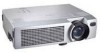
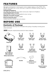
... grundig for closer viewing. NOTE • Keep the original packing material for Remote Control Transmitter AUTO MENU KEYSTONE MENU SELECT POSITION RESET FREEZE MAGNIFY MUTE OFF VOLUME Remote Control Transmitter GEBRUIKSAANWIJZNG Lees voor het qebruik alstublieft deze handleiding aandachtig door, om volledig profijt te hebben van de uitgebreide mogelijkheden. Outstanding Brightness The UHB lamp and high-efficiency optical system assure a high level of the...
... grundig for closer viewing. NOTE • Keep the original packing material for Remote Control Transmitter AUTO MENU KEYSTONE MENU SELECT POSITION RESET FREEZE MAGNIFY MUTE OFF VOLUME Remote Control Transmitter GEBRUIKSAANWIJZNG Lees voor het qebruik alstublieft deze handleiding aandachtig door, om volledig profijt te hebben van de uitgebreide mogelijkheden. Outstanding Brightness The UHB lamp and high-efficiency optical system assure a high level of the...

User Manual
Page 4
...BEFORE USE (continued) Part Names Speaker Handle Hook Zoom Knob Focus Ring Remote Control Sensor Power Switch AC Inlet (to the Power Cord) Ventilation Openings (Intake) Foot Adjuster FRONT/LEFT VIEW OF THE PROJECTOR Lens Lens Cap Control Panel (Refer to P.9 "OPERATIONS") STANDBY/ON Button KEYSTONE Button Foot Adjuster Button Filter Cover ( ) Air Filter and Intake for the Cooling Fan Rear Foot Adjuster REAR/RIGHT VIEW OF THE PROJECTOR INPUT Button LAMP Indicator TEMP Indicator POWER Indicator RESET Button MENU Button Ventilation Openings (exhaust) Terminal Panel (Refer below) S-VIDEO...
...BEFORE USE (continued) Part Names Speaker Handle Hook Zoom Knob Focus Ring Remote Control Sensor Power Switch AC Inlet (to the Power Cord) Ventilation Openings (Intake) Foot Adjuster FRONT/LEFT VIEW OF THE PROJECTOR Lens Lens Cap Control Panel (Refer to P.9 "OPERATIONS") STANDBY/ON Button KEYSTONE Button Foot Adjuster Button Filter Cover ( ) Air Filter and Intake for the Cooling Fan Rear Foot Adjuster REAR/RIGHT VIEW OF THE PROJECTOR INPUT Button LAMP Indicator TEMP Indicator POWER Indicator RESET Button MENU Button Ventilation Openings (exhaust) Terminal Panel (Refer below) S-VIDEO...

User Manual
Page 5
... cause vision problems. AVOID EXPOSURELASER RADIATIONS IS EMITTED FROM THIS APERTURE CAUTION LASER RADIATIONDO NOT STARE INTO BEAM MAX. ENGLISH-4 BEFORE USE (continued) Part Names (continued) STANDBY/ON Button VIDEO Button Disk Pad Used to operate the mouse shift function and left mouse button. , , , Button Used to operate the mouse shift function. WARNING • The laser pointer of the remote control transmitter is activated. KEYSTONE Button RESET Button Used to click...
... cause vision problems. AVOID EXPOSURELASER RADIATIONS IS EMITTED FROM THIS APERTURE CAUTION LASER RADIATIONDO NOT STARE INTO BEAM MAX. ENGLISH-4 BEFORE USE (continued) Part Names (continued) STANDBY/ON Button VIDEO Button Disk Pad Used to operate the mouse shift function and left mouse button. , , , Button Used to operate the mouse shift function. WARNING • The laser pointer of the remote control transmitter is activated. KEYSTONE Button RESET Button Used to click...

User Manual
Page 7
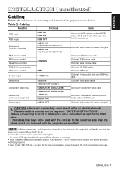
... manual. • When you must connect it with ventilation holes blocked. • Do not install LCD projector in smoke effected environment. Smoke residue may cause the heat inside to instructions of the screen size and projection distance. Release the button to install it with the ground terminal provided at the building using an optional three-core power-supply cord. • Please basically use liquid crystal projector by the lens...
... manual. • When you must connect it with ventilation holes blocked. • Do not install LCD projector in smoke effected environment. Smoke residue may cause the heat inside to instructions of the screen size and projection distance. Release the button to install it with the ground terminal provided at the building using an optional three-core power-supply cord. • Please basically use liquid crystal projector by the lens...
User Manual
Page 8
... some RGB input modes, the optional Mac adapter is compatible with the device. • Secure the screws on the connectors and tighten. • For some of these modes will not be possible with the core set to the projector side. ENGLISH-7 Please read instruction manuals of the devices to be used with this manual and the separate "SAFETY INSTRUCTIONS". • Before connecting, turn off to...
... some RGB input modes, the optional Mac adapter is compatible with the device. • Secure the screws on the connectors and tighten. • For some of these modes will not be possible with the core set to the projector side. ENGLISH-7 Please read instruction manuals of the devices to be used with this manual and the separate "SAFETY INSTRUCTIONS". • Before connecting, turn off to...
User Manual
Page 9
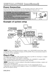
... image output (setting CRT display or simultaneous display of the projector to instructions of the accompanying manual "SAFETY INSTRUCTIONS" and this function by other connecting. Plug & Play This projector is recognized as a plug & play does not operate correctly. Connect the AC inlet of LCD and CRT). Power outlet Power Cord AC Inlet Example of system setup DVD Player S-Video Tape Recorder COMPONENT VIDEO AUDIO IN VIDEO IN S-VIDEO IN Display Monitor 1 RGB IN 2 AUDIO 1 2 AUDIO...
... image output (setting CRT display or simultaneous display of the projector to instructions of the accompanying manual "SAFETY INSTRUCTIONS" and this function by other connecting. Plug & Play This projector is recognized as a plug & play does not operate correctly. Connect the AC inlet of LCD and CRT). Power outlet Power Cord AC Inlet Example of system setup DVD Player S-Video Tape Recorder COMPONENT VIDEO AUDIO IN VIDEO IN S-VIDEO IN Display Monitor 1 RGB IN 2 AUDIO 1 2 AUDIO...
User Manual
Page 10
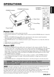
...the control panel or the remote control transmitter. ENGLISH OPERATIONS POWER Indicator STANDBY/ON Button STANDBY/ ON Button STANDBY/ON BLANK LASER VIDEO RGB Power Switch Zoom Knob Focus Ring Lens Cap AUTO MENU KEYSTONE MENU SELECT POSITION RESET FREEZE MAGNIFY MUTE OFF VOLUME Power ON 1. Adjust picture size using the focus ring . The POWER indicator ceases blinking and turns to [O]. 3. The system assumes the Standby mode when cooling is extinguished and lamp cooling begins. The POWER indicator blinks orange during lamp cooling. Open the slide lens door...
...the control panel or the remote control transmitter. ENGLISH OPERATIONS POWER Indicator STANDBY/ON Button STANDBY/ ON Button STANDBY/ON BLANK LASER VIDEO RGB Power Switch Zoom Knob Focus Ring Lens Cap AUTO MENU KEYSTONE MENU SELECT POSITION RESET FREEZE MAGNIFY MUTE OFF VOLUME Power ON 1. Adjust picture size using the focus ring . The POWER indicator ceases blinking and turns to [O]. 3. The system assumes the Standby mode when cooling is extinguished and lamp cooling begins. The POWER indicator blinks orange during lamp cooling. Open the slide lens door...

User Manual
Page 12
... / button. A signal type appropriate for VIDEO on the Image menu. AUTO Automatic Adjustment at Video Input : Press the AUTO button. Horizontal position(H.POSIT), vertical position (V.POSIT),clock phase (H.PHASE), and horizontal size(H.SIZE) are displayed with the and buttons as the mouse control button. MUTE Set/Clear Mute Mode : Press the MUTE button. Table 3. No image is selected automatically. ENGLISH OPERATIONS (continued) Items indicated by (*) may be used . MENU Menu Display Start/Stop: Press the MENU button. Push the MENU SELECT button...
... / button. A signal type appropriate for VIDEO on the Image menu. AUTO Automatic Adjustment at Video Input : Press the AUTO button. Horizontal position(H.POSIT), vertical position (V.POSIT),clock phase (H.PHASE), and horizontal size(H.SIZE) are displayed with the and buttons as the mouse control button. MUTE Set/Clear Mute Mode : Press the MUTE button. Table 3. No image is selected automatically. ENGLISH OPERATIONS (continued) Items indicated by (*) may be used . MENU Menu Display Start/Stop: Press the MENU button. Push the MENU SELECT button...
User Manual
Page 14
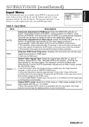
... the input signal is incorrect). SETUP INPUT AUTO RGB VIDEO HDTV IMAGE OPT. Use with some input signals. VIDEO (**) HDTV Select Video Signal Type: Select the signal type with the and buttons. the display position or color is selected automatically. ENGLISH-13 The function indicated (**) are automatically adjusted. RGB Displays RGB Input Frequency: Displays the horizontal and vertical sync signal frequencies for RGB input. • Valid only at maximum size in this case may correct this problem...
... the input signal is incorrect). SETUP INPUT AUTO RGB VIDEO HDTV IMAGE OPT. Use with some input signals. VIDEO (**) HDTV Select Video Signal Type: Select the signal type with the and buttons. the display position or color is selected automatically. ENGLISH-13 The function indicated (**) are automatically adjusted. RGB Displays RGB Input Frequency: Displays the horizontal and vertical sync signal frequencies for RGB input. • Valid only at maximum size in this case may correct this problem...

User Manual
Page 17
... START UP MENU COLOR "NO INPUT IS DETECTED ON ***" or "SYNC IS OUT OF RANGE LANGUAGE AUTO OFF ON ***" message while no signal is received. ENGLISH-16 The volume adjustment bar is displayed by input of a non-standard signal, the image is cleared and the complete screen is displayed in blue when there is no signal is not received for the set with the / button. In such cases, remove the signal...
... START UP MENU COLOR "NO INPUT IS DETECTED ON ***" or "SYNC IS OUT OF RANGE LANGUAGE AUTO OFF ON ***" message while no signal is received. ENGLISH-16 The volume adjustment bar is displayed by input of a non-standard signal, the image is cleared and the complete screen is displayed in blue when there is no signal is not received for the set with the / button. In such cases, remove the signal...
User Manual
Page 18
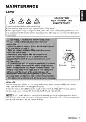
... do not use the projector with the lamp cover removed. See Table 9 of P.20 and Table 10 of the Table 12. NOTE • The LAMP indicator is switched ON. WARNING • For disposal of used for a long period of time. Replace the lamp if the LAMP indicator is red, or the CHANGE THE LAMP message appears when the projector is also red when the lamp unit reaches high temperature. ENGLISH MAINTENANCE Lamp HIGH VOLTAGE HIGH TEMPERATURE HIGH PRESSURE Contact...
... do not use the projector with the lamp cover removed. See Table 9 of P.20 and Table 10 of the Table 12. NOTE • The LAMP indicator is switched ON. WARNING • For disposal of used for a long period of time. Replace the lamp if the LAMP indicator is red, or the CHANGE THE LAMP message appears when the projector is also red when the lamp unit reaches high temperature. ENGLISH MAINTENANCE Lamp HIGH VOLTAGE HIGH TEMPERATURE HIGH PRESSURE Contact...

User Manual
Page 19
... MENU button on the remote control transmitter, or the RESET button on the bottom of the lamp case may result in over 10 minutes. 1. Check that screws are tightened properly. Install the new lamp and tighten the three screws firmly. Gently turn it upside down. 4. Resetting the Lamp Timer Reset the lamp timer after the LAMP indicator is red, or the CHANGE THE LAMP message is not reset correctly. The 'LAMP xxxx hr' message will not operate properly if the lamp timer is displayed...
... MENU button on the remote control transmitter, or the RESET button on the bottom of the lamp case may result in over 10 minutes. 1. Check that screws are tightened properly. Install the new lamp and tighten the three screws firmly. Gently turn it upside down. 4. Resetting the Lamp Timer Reset the lamp timer after the LAMP indicator is red, or the CHANGE THE LAMP message is not reset correctly. The 'LAMP xxxx hr' message will not operate properly if the lamp timer is displayed...

User Manual
Page 20
... cleaned and checked by yourself is clogged with a soft cloth. Clean the air filter with lens cleaning paper. Do not touch the lens with a soft, dry cloth. are not easily removed, use detergents or chemicals other than those noted above (e.g. For the optional air filter, see the item "Option Parts" of approximately 300 hours. 1. Switch the projector power supply OFF, and remove the power cord from the power outlet before beginning maintenance work . Remove...
... cleaned and checked by yourself is clogged with a soft cloth. Clean the air filter with lens cleaning paper. Do not touch the lens with a soft, dry cloth. are not easily removed, use detergents or chemicals other than those noted above (e.g. For the optional air filter, see the item "Option Parts" of approximately 300 hours. 1. Switch the projector power supply OFF, and remove the power cord from the power outlet before beginning maintenance work . Remove...

User Manual
Page 21
... every time power is recommended to replace the lamp soon. OSD Messages Message Contents CHANGE THE LAMP The usage time of the input signal is active. The usage time of the equipment and the signal source. automatically in P.17 ~18 "Lamp". THE POWER WILL TURN OFF AFTER 0 hr. Check the specifications of lamp will be switched OFF AFTER ** hr. Table 9. Prepare a (*1) new lamp as described below may appear on the screen at power ON. Check signal input connections and signal sources...
... every time power is recommended to replace the lamp soon. OSD Messages Message Contents CHANGE THE LAMP The usage time of the input signal is active. The usage time of the equipment and the signal source. automatically in P.17 ~18 "Lamp". THE POWER WILL TURN OFF AFTER 0 hr. Check the specifications of lamp will be switched OFF AFTER ** hr. Table 9. Prepare a (*1) new lamp as described below may appear on the screen at power ON. Check signal input connections and signal sources...

User Manual
Page 22
... TROUBLESHOOTING (continued) Indicators Message The POWER indicator, LAMP indicator, and TEMP indicator are blocked, whether the air filter is not found . Blinks red - Cooling. Blinks green Turns off Turns off The Standby mode has been set. Blinks /Lights red Turns off Cooling. Contact your dealer if the same problem occurs again. Blinks orange Turns off Turns off Blinks red The cooling fan is found , or hasn't been fitted in the fan, and switch power ON again. Turns off Lights red cools. Lights Blinks Blinks Check whether the ambient temperature...
... TROUBLESHOOTING (continued) Indicators Message The POWER indicator, LAMP indicator, and TEMP indicator are blocked, whether the air filter is not found . Blinks red - Cooling. Blinks green Turns off Turns off The Standby mode has been set. Blinks /Lights red Turns off Cooling. Contact your dealer if the same problem occurs again. Blinks orange Turns off Turns off Blinks red The cooling fan is found , or hasn't been fitted in the fan, and switch power ON again. Turns off Lights red cools. Lights Blinks Blinks Check whether the ambient temperature...
User Manual
Page 23
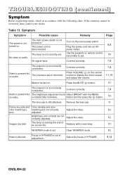
... focus or H PHASE. 9,12 ENGLISH-22 Press VOLUME on the remote control or display the menu screen and adjust the volume. 7,8 11,15 Mute is not correctly set . 10 No video or audio. adjusted. Replace with the MENU no audio. The input is turned on . Use the projector or remote control transmitter to minimum. Video is present but The brightness adjustment knob Select BRIGHT with a new lamp. 17 WHISPER mode is not turned on the main power switch. Connect...
... focus or H PHASE. 9,12 ENGLISH-22 Press VOLUME on the remote control or display the menu screen and adjust the volume. 7,8 11,15 Mute is not correctly set . 10 No video or audio. adjusted. Replace with the MENU no audio. The input is turned on . Use the projector or remote control transmitter to minimum. Video is present but The brightness adjustment knob Select BRIGHT with a new lamp. 17 WHISPER mode is not turned on the main power switch. Connect...

User Manual
Page 32
... power supply is switched ON, and when the lamp is shorter than indicated by the computer. TECHNICAL (continued) Requesting projector status (Get command) (1) Send the request code Header + Command data ('02H'+'00H'+ type (2 bytes) +'00H'+'00H') from the computer to the projector. (2) The projector changes the setting based on the above setting code. (3) The projector returns the response code '06H' to the computer. Using the projector default settings (Reset Command) (1) The computer sends the default setting code Header + Command data...
... power supply is switched ON, and when the lamp is shorter than indicated by the computer. TECHNICAL (continued) Requesting projector status (Get command) (1) Send the request code Header + Command data ('02H'+'00H'+ type (2 bytes) +'00H'+'00H') from the computer to the projector. (2) The projector changes the setting based on the above setting code. (3) The projector returns the response code '06H' to the computer. Using the projector default settings (Reset Command) (1) The computer sends the default setting code Header + Command data...
User Manual
Page 34
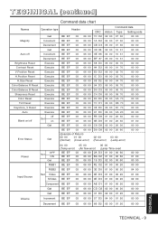
TECHNICAL (continued) Command data chart Names Operation type Header Command data CRC Action Type Setting code Get BE ... BE EF 03 06 00 08 86 02 00 10 31 00 00 Auto off Increment BE EF 03 06 00 6E 86 04 00 10 31 ...Size Reset Execute BE EF 03 06 00 68 D2 06 00 04 70 00 00 Color Balance R Reset Execute BE EF 03 06 00 94 D3 06 00 05 70 00 00 Color Balance B Reset...00 00 Error Status (Example of Return) 00 00 01 00 02 00 03 00 Get (Normal) (Cover-error) (Fan-error) (Lamp-error) Power OFF Set ON Get RGB1 04 00 05 00 06 00 (Temp-error) (Air flow-error) (Lamp-Time-over) ...
TECHNICAL (continued) Command data chart Names Operation type Header Command data CRC Action Type Setting code Get BE ... BE EF 03 06 00 08 86 02 00 10 31 00 00 Auto off Increment BE EF 03 06 00 6E 86 04 00 10 31 ...Size Reset Execute BE EF 03 06 00 68 D2 06 00 04 70 00 00 Color Balance R Reset Execute BE EF 03 06 00 94 D3 06 00 05 70 00 00 Color Balance B Reset...00 00 Error Status (Example of Return) 00 00 01 00 02 00 03 00 Get (Normal) (Cover-error) (Fan-error) (Lamp-error) Power OFF Set ON Get RGB1 04 00 05 00 06 00 (Temp-error) (Air flow-error) (Lamp-Time-over) ...

User Manual
Page 38
... technician for help. REGULATORY NOTICES - 1 Increase the separation between the equipment and receiver. - For the Customers in a particular installation. These limits are met. However, there is connected. - REGULATORY NOTICES FCC Statement Warning WARNING: This equipment has been tested and found to comply with the limits for a Class B digital device, pursuant to the projector side. Use the cables which the...
... technician for help. REGULATORY NOTICES - 1 Increase the separation between the equipment and receiver. - For the Customers in a particular installation. These limits are met. However, there is connected. - REGULATORY NOTICES FCC Statement Warning WARNING: This equipment has been tested and found to comply with the limits for a Class B digital device, pursuant to the projector side. Use the cables which the...


