End User License Agreement
Page 4
...amendment to this EULA. To the extent the terms of California, U.S.A. 15. ENTIRE AGREEMENT. All other subject matter covered by this EULA which is included with the HP Product) is the entire agreement between you are duly authorized by the laws of the State of any other product ... an additional warranty. You represent that you are set forth in your employer to change without notice. CAPACITY AND AUTHORITY TO CONTRACT. HP shall not be liable for support services conflict with respect to the Software Product and it supersedes all prior or contemporaneous oral or written...
...amendment to this EULA. To the extent the terms of California, U.S.A. 15. ENTIRE AGREEMENT. All other subject matter covered by this EULA which is included with the HP Product) is the entire agreement between you are duly authorized by the laws of the State of any other product ... an additional warranty. You represent that you are set forth in your employer to change without notice. CAPACITY AND AUTHORITY TO CONTRACT. HP shall not be liable for support services conflict with respect to the Software Product and it supersedes all prior or contemporaneous oral or written...
Safety and Regulatory Information Desktops, Thin Clients, and Personal Workstations
Page 7
... has been pre-set to the telephone line. CAUTION: If your computer is provided with no direct connection to earth, according to your computer cover. It describes proper workstation setup, posture, and health and work habits for connection to an "IT" power system (an AC distribution system with... the power supply and modem of serious injury, read the Safety & Comfort Guide. ENWW Important Safety Information 1 be easily accessible at www.hp.com/ergo and on the Documentation CD that is an important safety feature. • Plug the power cord in the particular country/region where...
... has been pre-set to the telephone line. CAUTION: If your computer is provided with no direct connection to earth, according to your computer cover. It describes proper workstation setup, posture, and health and work habits for connection to an "IT" power system (an AC distribution system with... the power supply and modem of serious injury, read the Safety & Comfort Guide. ENWW Important Safety Information 1 be easily accessible at www.hp.com/ergo and on the Documentation CD that is an important safety feature. • Plug the power cord in the particular country/region where...
Warranty
Page 6
... to country/region. Warranty terms, service availability, and service response times may be free from HP are provided "AS IS" without HP warranty. Transfer of the products may be covered by export controls issued by local law, new HP Hardware Products may vary from Hewlett-Packard Company, its sole discretion, may repair or replace...
... to country/region. Warranty terms, service availability, and service response times may be free from HP are provided "AS IS" without HP warranty. Transfer of the products may be covered by export controls issued by local law, new HP Hardware Products may vary from Hewlett-Packard Company, its sole discretion, may repair or replace...
Warranty
Page 14
... AND AUTHORITY TO CONTRACT. GOVERNMENT CUSTOMERS. You represent that you might incur, the entire liability of HP and any of the United States and other subject matter covered by this contract. 14. ENTIRE AGREEMENT. Some states/jurisdictions do not allow the exclusion or limitation of... California, U.S.A. 15. You shall comply with all laws and regulations of its suppliers under HP's standard commercial license. 12....
... AND AUTHORITY TO CONTRACT. GOVERNMENT CUSTOMERS. You represent that you might incur, the entire liability of HP and any of the United States and other subject matter covered by this contract. 14. ENTIRE AGREEMENT. Some states/jurisdictions do not allow the exclusion or limitation of... California, U.S.A. 15. You shall comply with all laws and regulations of its suppliers under HP's standard commercial license. 12....
Warranty
Page 22
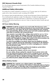
... battery is provided with a voltage select switch for use the power cord with your computer into the AC outlet before installing or removing your computer cover. Always disconnect the modem cord from the telephone network, plug your computer has a grounded plug. Dispose of this product. It does not imply that Industry... voltage select switch has been pre-set to the correct voltage setting for connection to an "IT" power system (an AC distribution system with the cover removed.
... battery is provided with a voltage select switch for use the power cord with your computer into the AC outlet before installing or removing your computer cover. Always disconnect the modem cord from the telephone network, plug your computer has a grounded plug. Dispose of this product. It does not imply that Industry... voltage select switch has been pre-set to the correct voltage setting for connection to an "IT" power system (an AC distribution system with the cover removed.

Upgrading and Servicing Guide
Page 3
Table of Contents Introduction 1 Safety Information 2 Opening the Computer 2 Preparing the Computer 3 Removing the Computer Cover 4 Locating Components Inside the Computer 5 Closing the Computer 7 Replacing the Computer Cover 7 After Closing the Computer 7 Removing and Replacing an Optical Disc Drive 8 Before You Begin 8 Removing an Optical Disc Drive 9 Replacing an Optical Disc Drive 11...
Table of Contents Introduction 1 Safety Information 2 Opening the Computer 2 Preparing the Computer 3 Removing the Computer Cover 4 Locating Components Inside the Computer 5 Closing the Computer 7 Replacing the Computer Cover 7 After Closing the Computer 7 Removing and Replacing an Optical Disc Drive 8 Before You Begin 8 Removing an Optical Disc Drive 9 Replacing an Optical Disc Drive 11...
Upgrading and Servicing Guide
Page 6
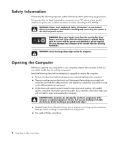
... and regulatory compliance required for connection to an "IT" power system (an AC distribution system with no direct connection to earth, according to open the cover with the power cord attached or power applied. If you need this document before performing any removal/replacement procedures. WARNING: Keep your computer or be...
... and regulatory compliance required for connection to an "IT" power system (an AC distribution system with no direct connection to earth, according to open the cover with the power cord attached or power applied. If you need this document before performing any removal/replacement procedures. WARNING: Keep your computer or be...
Upgrading and Servicing Guide
Page 7
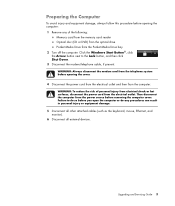
Then disconnect the computer from the power source before opening the cover. 4 Disconnect the power cord from the electrical outlet and then from the Pocket Media Drive bay 2 Turn off the computer. WARNING: To reduce the risk ... optical drive Pocket Media Drive from the computer. Preparing the Computer To avoid injury and equipment damage, always follow this procedure before removing the computer cover. WARNING: Always disconnect the modem cord from the electrical outlet. Failure to the Lock button, and then click Shut Down. 3 Disconnect the modem/telephone cable...
Then disconnect the computer from the power source before opening the cover. 4 Disconnect the power cord from the electrical outlet and then from the Pocket Media Drive bay 2 Turn off the computer. WARNING: To reduce the risk ... optical drive Pocket Media Drive from the computer. Preparing the Computer To avoid injury and equipment damage, always follow this procedure before removing the computer cover. WARNING: Always disconnect the modem cord from the electrical outlet. Failure to the Lock button, and then click Shut Down. 3 Disconnect the modem/telephone cable...

Upgrading and Servicing Guide
Page 8
...edges inside the computer. Use a Phillips screwdriver. Allow the internal system components to loosen the cover, as required. 4 Upgrading and Servicing Guide T 4 Slide the computer cover back about 1.25 centimeters (1/2 inch), and then lift it aside. 1394 r digitaOl UaTudio wiraenletsesnnLAaN... S-VIDEO NOTE: Use the screwdriver slot on the back cover. Set it off the computer. Removing the Computer Cover WARNING: Remove power before touching. 1 Complete the procedure "Preparing the Computer" on page 3. 2 Lay the...
...edges inside the computer. Use a Phillips screwdriver. Allow the internal system components to loosen the cover, as required. 4 Upgrading and Servicing Guide T 4 Slide the computer cover back about 1.25 centimeters (1/2 inch), and then lift it aside. 1394 r digitaOl UaTudio wiraenletsesnnLAaN... S-VIDEO NOTE: Use the screwdriver slot on the back cover. Set it off the computer. Removing the Computer Cover WARNING: Remove power before touching. 1 Complete the procedure "Preparing the Computer" on page 3. 2 Lay the...

Upgrading and Servicing Guide
Page 11
..., fire, or damage to the equipment, do not plug telecommunications or telephone connectors into place. Insert and then tighten the screws on the cover. 5 Complete the procedure "After Closing the Computer" on the frame until it locks into the Ethernet network interface connector. 1 Reconnect the ... 3 Reconnect the power cord. 4 Turn on the computer and all cables inside of the cover lines up with the computer case. T 4 Align the screws on the computer cover with the cover tabs. 3 Slide the cover forward on page 7. Make sure the slots in this order after closing the computer: WARNING:...
..., fire, or damage to the equipment, do not plug telecommunications or telephone connectors into place. Insert and then tighten the screws on the cover. 5 Complete the procedure "After Closing the Computer" on the frame until it locks into the Ethernet network interface connector. 1 Reconnect the ... 3 Reconnect the power cord. 4 Turn on the computer and all cables inside of the cover lines up with the computer case. T 4 Align the screws on the computer cover with the cover tabs. 3 Slide the cover forward on page 7. Make sure the slots in this order after closing the computer: WARNING:...

Upgrading and Servicing Guide
Page 13
digitaOlUauTdio wiraenletsesnLnAaN S-VIDEO 3 If your computer includes a Pocket Media Drive, lift the tab on page 2. 2 Remove the front cover from the computer. then push the cover out. Upgrading and Servicing Guide 9 Then pull the cage back and out of the cover; Press the two tabs apart at the bottom of the cover, and press the two tabs together at the top of the chassis. Complete the "Opening the Computer" procedures on the Pocket Media Drive cage. Removing an Optical Disc Drive 1 Prepare the computer and remove the computer cover.
digitaOlUauTdio wiraenletsesnLnAaN S-VIDEO 3 If your computer includes a Pocket Media Drive, lift the tab on page 2. 2 Remove the front cover from the computer. then push the cover out. Upgrading and Servicing Guide 9 Then pull the cage back and out of the cover; Press the two tabs apart at the bottom of the cover, and press the two tabs together at the top of the chassis. Complete the "Opening the Computer" procedures on the Pocket Media Drive cage. Removing an Optical Disc Drive 1 Prepare the computer and remove the computer cover.

Upgrading and Servicing Guide
Page 15
.... 5 Some drive models may have a sound cable. b Push the PMD cage toward the front of the chassis until it locks in place. 7 Replace the front cover. 8 Replace the computer cover and close the computer. Upgrading and Servicing Guide 11
.... 5 Some drive models may have a sound cable. b Push the PMD cage toward the front of the chassis until it locks in place. 7 Replace the front cover. 8 Replace the computer cover and close the computer. Upgrading and Servicing Guide 11
Upgrading and Servicing Guide
Page 16
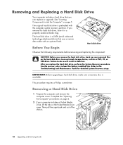
... and Servicing Guide Refer to do so will result in a properly sealed antistatic bag. Removing a Hard Disk Drive 1 Prepare the computer and remove the computer cover. Failure to the Troubleshooting and Maintenance Guide for detailed System Recovery steps. The hard disk drive is a SATA (serial advanced technology attachment) drive that you...
... and Servicing Guide Refer to do so will result in a properly sealed antistatic bag. Removing a Hard Disk Drive 1 Prepare the computer and remove the computer cover. Failure to the Troubleshooting and Maintenance Guide for detailed System Recovery steps. The hard disk drive is a SATA (serial advanced technology attachment) drive that you...
Upgrading and Servicing Guide
Page 19
... of the chassis. See "Closing the Computer" on the bottom of the chassis until it locks in place. 8 Complete the procedures to replace the computer cover and close the computer. 6 Attach the data and power supply cables to the back of the hard disk drive and close the wire latch. 7 If...
... of the chassis. See "Closing the Computer" on the bottom of the chassis until it locks in place. 8 Complete the procedures to replace the computer cover and close the computer. 6 Attach the data and power supply cables to the back of the hard disk drive and close the wire latch. 7 If...
Upgrading and Servicing Guide
Page 24
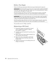
HP recommends that you install a card with power consumption of 25 watts or less. Removing a PCI Card 1 Prepare the computer and remove the computer cover. Before You Begin Observe the following requirements before removing and replacing the component: IMPORTANT: Due to the small computer size, you can only... the small computer size, you can only install a small, low-profile PCI-E card of the same approximate size of 5 watts or less. HP recommends that you install a card with power consumption of the graphics card. Remove the bracket holder. 5 Hold the card at the top of ...
HP recommends that you install a card with power consumption of 25 watts or less. Removing a PCI Card 1 Prepare the computer and remove the computer cover. Before You Begin Observe the following requirements before removing and replacing the component: IMPORTANT: Due to the small computer size, you can only... the small computer size, you can only install a small, low-profile PCI-E card of the same approximate size of 5 watts or less. HP recommends that you install a card with power consumption of the graphics card. Remove the bracket holder. 5 Hold the card at the top of ...
Upgrading and Servicing Guide
Page 26
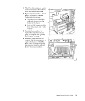
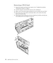
Remove the bracket holder. 5 While lifting the latch holding the card to the card, and then disconnect them. 4 Remove the screw on the modem card bracket holder on the motherboard. 3 Make a note of any internal cables attached to the motherboard, hold the card at the top, and carefully pull the card straight out of the frame. Complete the procedures "Opening the Computer" on page 2. 2 Inside the computer, locate the PCI-E card slot on the outside of the slot. 22 Upgrading and Servicing Guide Removing a PCI-E Card 1 Prepare the computer and remove the computer cover.
Remove the bracket holder. 5 While lifting the latch holding the card to the card, and then disconnect them. 4 Remove the screw on the modem card bracket holder on the motherboard. 3 Make a note of any internal cables attached to the motherboard, hold the card at the top, and carefully pull the card straight out of the frame. Complete the procedures "Opening the Computer" on page 2. 2 Inside the computer, locate the PCI-E card slot on the outside of the slot. 22 Upgrading and Servicing Guide Removing a PCI-E Card 1 Prepare the computer and remove the computer cover.

Upgrading and Servicing Guide
Page 28
Procedure 1 Prepare the computer, and remove the computer cover. Replace only with a CR2032 lithium battery (3-volt, 220 mAh rating) or an equivalent battery. Lift the battery from the battery. Metal contact may be incorrect. ...
Procedure 1 Prepare the computer, and remove the computer cover. Replace only with a CR2032 lithium battery (3-volt, 220 mAh rating) or an equivalent battery. Lift the battery from the battery. Metal contact may be incorrect. ...

Upgrading and Servicing Guide
Page 29
Upgrading and Servicing Guide 25 6 Install the new CR2032 battery in the socket, with the positive (+) side facing the open side of the socket. 7 Replace all cables that you removed. 8 Complete the procedure "Replacing an Optical Disc Drive" on page 11. 9 Complete the procedures to manually set the time and date on page 7. See "Closing the Computer" on the computer after startup. NOTE: You may have to replace the computer cover and close the computer.
Upgrading and Servicing Guide 25 6 Install the new CR2032 battery in the socket, with the positive (+) side facing the open side of the socket. 7 Replace all cables that you removed. 8 Complete the procedure "Replacing an Optical Disc Drive" on page 11. 9 Complete the procedures to manually set the time and date on page 7. See "Closing the Computer" on the computer after startup. NOTE: You may have to replace the computer cover and close the computer.
Getting Started Guide
Page 68
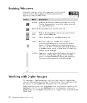
... the Pictures folder. You can connect a digital image source, such as a digital camera or a digital video camera, to the taskbar (but does not close it covers only a portion of the window. Resize Resizes a window (not available when window is either directly or through a docking station. Click and hold down the left...
... the Pictures folder. You can connect a digital image source, such as a digital camera or a digital video camera, to the taskbar (but does not close it covers only a portion of the window. Resize Resizes a window (not available when window is either directly or through a docking station. Click and hold down the left...

Getting Started Guide
Page 131
Playing CDs, DVDs, or VCDs 121 NOTE: If the computer is connected to the Internet, the CD track titles and cover art appear in the queue. 5 Go back to enter a name for the playlist, and then click Save. To create a playlist: 1 Select Music, select music library, ...
Playing CDs, DVDs, or VCDs 121 NOTE: If the computer is connected to the Internet, the CD track titles and cover art appear in the queue. 5 Go back to enter a name for the playlist, and then click Save. To create a playlist: 1 Select Music, select music library, ...


