Safety and Regulatory Information Desktops, Thin Clients, and Personal Workstations
Page 29
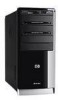
... Hazardous Substances and Elements (continued) Part Name Lead (Pb) Mercury (Hg) Cadmium (Cd) Hexavalent Chromium (Cr(VI)) Memory X O O O I/O PCAs X O O O Power supply X O O O Keyboard X O O O Mouse X O O O Chassis/Other X O O O Fans X O O O Internal/External Media Reading X O O O Devices External Control Devices X O O O Cable X O O O Hard Disk Drive X O O O Display X X O O Polybrominated biphenyls (PBB) Polybrominated diphenyl ethers (PBDE) O O O O O O O O O O O O O O O O O O O O O O O O O: Indicates...
... Hazardous Substances and Elements (continued) Part Name Lead (Pb) Mercury (Hg) Cadmium (Cd) Hexavalent Chromium (Cr(VI)) Memory X O O O I/O PCAs X O O O Power supply X O O O Keyboard X O O O Mouse X O O O Chassis/Other X O O O Fans X O O O Internal/External Media Reading X O O O Devices External Control Devices X O O O Cable X O O O Hard Disk Drive X O O O Display X X O O Polybrominated biphenyls (PBB) Polybrominated diphenyl ethers (PBDE) O O O O O O O O O O O O O O O O O O O O O O O O O: Indicates...

Getting Started
Page 54
... also have a reduced-power state called Away mode. You can perform tasks such as to make repairs, install new hardware or cards in the computer chassis, or change a battery. Away mode turns off the display and mutes the audio, but otherwise keeps the computer operational. During Away mode, the computer can...
... also have a reduced-power state called Away mode. You can perform tasks such as to make repairs, install new hardware or cards in the computer chassis, or change a battery. Away mode turns off the display and mutes the audio, but otherwise keeps the computer operational. During Away mode, the computer can...
Getting Started
Page 16
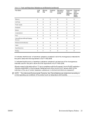
... Start Button on , and the computer is available. Hibernate mode saves the system memory to make repairs, install new hardware or cards in the computer chassis, or change a battery. To turn on the computer after a shut down the computer, you can perform tasks such as to a temporary file on the ...computer chassis. As an alternative to wake quickly and resume your work where you left off. and then goes to the Lock button. 4 Click Shut Down. 5 Turn...
... Start Button on , and the computer is available. Hibernate mode saves the system memory to make repairs, install new hardware or cards in the computer chassis, or change a battery. To turn on the computer after a shut down the computer, you can perform tasks such as to a temporary file on the ...computer chassis. As an alternative to wake quickly and resume your work where you left off. and then goes to the Lock button. 4 Click Shut Down. 5 Turn...

Getting Started Guide
Page 54
...your work to the hard disk; Sleep and Hibernate modes are power states. During Sleep mode, the computer hardware light remains on the computer chassis. Sleep mode saves your work where you left off the power for safety reasons, such as recording a scheduled TV program or streaming video ... you must turn off . saves your work to a remote location. and then goes to make repairs, install new hardware or cards in the computer chassis, or change a battery. As an alternative to the Lock button. 4 Click Shut Down. 5 Turn off the computer without pressing any open software programs...
...your work to the hard disk; Sleep and Hibernate modes are power states. During Sleep mode, the computer hardware light remains on the computer chassis. Sleep mode saves your work where you left off the power for safety reasons, such as recording a scheduled TV program or streaming video ... you must turn off . saves your work to a remote location. and then goes to make repairs, install new hardware or cards in the computer chassis, or change a battery. As an alternative to the Lock button. 4 Click Shut Down. 5 Turn off the computer without pressing any open software programs...
Upgrading and Servicing Guide
Page 7
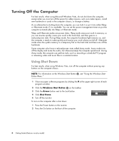
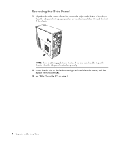
... PC To avoid injury and equipment damage, always follow this order after closing the PC: 1 Reconnect the power cord. A 3 Use the handle to the PC chassis. WARNING: Beware of electrical shock, fire, or damage to use a screwdriver the first time you installed an add-in this procedure in card, install any... page 2. 2 Loosen the thumbscrew (A) that secures the side panel to pull and slide the panel back about 1 inch (2.5 centimeters), and then lift it off the chassis. Upgrading and Servicing Guide 3 WARNING: To reduce the risk of sharp edges inside the...
... PC To avoid injury and equipment damage, always follow this order after closing the PC: 1 Reconnect the power cord. A 3 Use the handle to the PC chassis. WARNING: Beware of electrical shock, fire, or damage to use a screwdriver the first time you installed an add-in this procedure in card, install any... page 2. 2 Loosen the thumbscrew (A) that secures the side panel to pull and slide the panel back about 1 inch (2.5 centimeters), and then lift it off the chassis. Upgrading and Servicing Guide 3 WARNING: To reduce the risk of sharp edges inside the...
Upgrading and Servicing Guide
Page 8
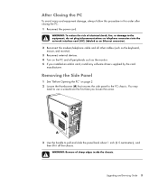
Replacing the Side Panel 1 Align the tabs at the bottom of the side panel to the ridge on the chassis and slide it toward the front of the chassis. Place the side panel in the chassis, and then replace the thumbscrew (A). 3 See "After Closing the PC" on page 3. 4 Upgrading and Servicing Guide A NOTE: There is a 3mm gap between the top of the side panel and the top of the chassis when the side panel is attached properly. 2 Ensure that the hole for the thumbscrew aligns with the hole in the proper position on the bottom of the chassis.
Replacing the Side Panel 1 Align the tabs at the bottom of the side panel to the ridge on the chassis and slide it toward the front of the chassis. Place the side panel in the chassis, and then replace the thumbscrew (A). 3 See "After Closing the PC" on page 3. 4 Upgrading and Servicing Guide A NOTE: There is a 3mm gap between the top of the side panel and the top of the chassis when the side panel is attached properly. 2 Ensure that the hole for the thumbscrew aligns with the hole in the proper position on the bottom of the chassis.

Upgrading and Servicing Guide
Page 9
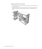
Removing the Front Panel This procedure is necessary only when removing or replacing an optical drive, memory card reader, an HP Pocket Media Drive, diskette drive, or the hard disk drive. 1 Pull the three tabs (B) away from the chassis toward the left to remove it. Upgrading and Servicing Guide 5 B 2 Swing the front panel away from the outside edge of the chassis.
Removing the Front Panel This procedure is necessary only when removing or replacing an optical drive, memory card reader, an HP Pocket Media Drive, diskette drive, or the hard disk drive. 1 Pull the three tabs (B) away from the chassis toward the left to remove it. Upgrading and Servicing Guide 5 B 2 Swing the front panel away from the outside edge of the chassis.
Upgrading and Servicing Guide
Page 10
Replacing the Front Panel 1 Align and insert the three hooks on the left side of the front panel with the holes on the left side of the chassis. 2 Swing the front panel around and press the three hooks on the right side of the front panel into the three holes on the right side of the chassis until the panel snaps into place. 6 Upgrading and Servicing Guide
Replacing the Front Panel 1 Align and insert the three hooks on the left side of the front panel with the holes on the left side of the chassis. 2 Swing the front panel around and press the three hooks on the right side of the front panel into the three holes on the right side of the chassis until the panel snaps into place. 6 Upgrading and Servicing Guide

Upgrading and Servicing Guide
Page 11
...optical drive bay, may be empty (knockout plate) or a CD-ROM, CD-RW, DVD-ROM, DVD+RW/+R, combination drive, or HP Personal Media Drive bay (select models) D HP Pocket Media Drive bay, a hard disk drive, or a diskette (floppy) drive (select models) E Front connector panel (no replacement ...instructions) F Hard disk drive and space for a second hard disk drive (located inside the chassis) (select models) NOTE: The connectors and components of your chassis model may...
...optical drive bay, may be empty (knockout plate) or a CD-ROM, CD-RW, DVD-ROM, DVD+RW/+R, combination drive, or HP Personal Media Drive bay (select models) D HP Pocket Media Drive bay, a hard disk drive, or a diskette (floppy) drive (select models) E Front connector panel (no replacement ...instructions) F Hard disk drive and space for a second hard disk drive (located inside the chassis) (select models) NOTE: The connectors and components of your chassis model may...
Upgrading and Servicing Guide
Page 12
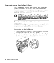
... software and drivers for the optical drive to work with your personal files on the hard disk drive to do so will result in the chassis.) 8 Upgrading and Servicing Guide CAUTION: Back up your PC for drive type and location. IMPORTANT: Before adding a new optical drive, make sure you have...Locating Components Inside the Computer" on page 1. 2 Release the drive by pulling the latch out away from the chassis and then pulling the drive part way out of the front of the chassis. (The latch drive brackets secure the drives in their respective positions in data loss. After replacing the hard ...
... software and drivers for the optical drive to work with your personal files on the hard disk drive to do so will result in the chassis.) 8 Upgrading and Servicing Guide CAUTION: Back up your PC for drive type and location. IMPORTANT: Before adding a new optical drive, make sure you have...Locating Components Inside the Computer" on page 1. 2 Release the drive by pulling the latch out away from the chassis and then pulling the drive part way out of the front of the chassis. (The latch drive brackets secure the drives in their respective positions in data loss. After replacing the hard ...

Upgrading and Servicing Guide
Page 13
... models only) in the center of each plug, and pull the plug from the drive connector. 4 Pull the drive out through the front of the chassis. To do so, insert a flat screwdriver into the knockout plate slot (A) and rotate the screwdriver to remove. For most drive cables, use a gentle rocking motion... power, data, and the sound cable, if available, from the back of the optical drive you want to break the knockout plate out of the chassis.
... models only) in the center of each plug, and pull the plug from the drive connector. 4 Pull the drive out through the front of the chassis. To do so, insert a flat screwdriver into the knockout plate slot (A) and rotate the screwdriver to remove. For most drive cables, use a gentle rocking motion... power, data, and the sound cable, if available, from the back of the optical drive you want to break the knockout plate out of the chassis.
Upgrading and Servicing Guide
Page 14
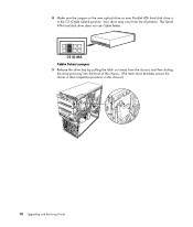
The Serial ATA hard disk drive does not use Cable Select. CS SL MA Cable Select jumper 5 Release the drive bay by pulling the latch out away from the illustration. 4 Make sure the jumper on the new optical drive or new Parallel ATA hard disk drive is in the chassis.) 10 Upgrading and Servicing Guide Your drive may vary from the chassis and then sliding the drive part way into the front of the chassis. (The latch drive brackets secure the drives in their respective positions in the CS (Cable Select) position.
The Serial ATA hard disk drive does not use Cable Select. CS SL MA Cable Select jumper 5 Release the drive bay by pulling the latch out away from the illustration. 4 Make sure the jumper on the new optical drive or new Parallel ATA hard disk drive is in the chassis.) 10 Upgrading and Servicing Guide Your drive may vary from the chassis and then sliding the drive part way into the front of the chassis. (The latch drive brackets secure the drives in their respective positions in the CS (Cable Select) position.
Upgrading and Servicing Guide
Page 15
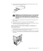
..., and then slide the drive part way out of the front of the chassis. See "Opening and Closing the PC" on page 1. 2 Release the HP Pocket Media or diskette (floppy), or hard disk drive, by removing the ...two screws on page 1. Reconnect the sound cable, if present. Removing the HP Pocket Media or Diskette or Hard Disk Drive 1 Complete the procedures to prepare the PC to remove ... may be lost. 7 Make sure the drive is pushed all the way in through the front of the chassis until it locks into place. 8 Make sure the drive latch pin is fully inserted into the hole labeled...
..., and then slide the drive part way out of the front of the chassis. See "Opening and Closing the PC" on page 1. 2 Release the HP Pocket Media or diskette (floppy), or hard disk drive, by removing the ...two screws on page 1. Reconnect the sound cable, if present. Removing the HP Pocket Media or Diskette or Hard Disk Drive 1 Complete the procedures to prepare the PC to remove ... may be lost. 7 Make sure the drive is pushed all the way in through the front of the chassis until it locks into place. 8 Make sure the drive latch pin is fully inserted into the hole labeled...
Upgrading and Servicing Guide
Page 16
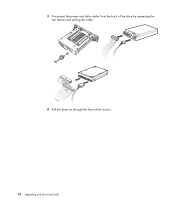
3 Disconnect the power and data cables from the back of the chassis. 12 Upgrading and Servicing Guide MASTER SLAVE To CPU 4 Pull the drive out through the front of the drive by squeezing the two latches and pulling the cable.
3 Disconnect the power and data cables from the back of the chassis. 12 Upgrading and Servicing Guide MASTER SLAVE To CPU 4 Pull the drive out through the front of the drive by squeezing the two latches and pulling the cable.

Upgrading and Servicing Guide
Page 17
... procedures to insert the screw into the holes labeled HDD. Upgrading and Servicing Guide 13 For the HP Pocket Media and diskette (floppy) drive, make sure to insert the screw into the holes labeled .... See "Removing the HP Pocket Media or Diskette or Hard Disk Drive" on page 11. 2 Slide the HP Pocket Media, diskette (floppy), or hard disk drive into the front of the chassis until it locks into place.... 3 Align the two screw holes on the chassis with the two screw...
... procedures to insert the screw into the holes labeled HDD. Upgrading and Servicing Guide 13 For the HP Pocket Media and diskette (floppy) drive, make sure to insert the screw into the holes labeled .... See "Removing the HP Pocket Media or Diskette or Hard Disk Drive" on page 11. 2 Slide the HP Pocket Media, diskette (floppy), or hard disk drive into the front of the chassis until it locks into place.... 3 Align the two screw holes on the chassis with the two screw...
Upgrading and Servicing Guide
Page 19
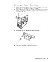
See "Opening and Closing the PC" on page 1. 2 Release the drive by removing the screw on the top of the chassis. Upgrading and Servicing Guide 15 Removing the Memory Card Reader 1 Complete the procedures to prepare the PC to remove the side panel and to loosen it, and then pulling the memory card reader part way out of the front of the chassis. 3 Disconnect the cable from the back of the memory card reader. 4 Pull the memory card reader out of the front of the memory card reader, sliding the reader to the left to remove the front panel.
See "Opening and Closing the PC" on page 1. 2 Release the drive by removing the screw on the top of the chassis. Upgrading and Servicing Guide 15 Removing the Memory Card Reader 1 Complete the procedures to prepare the PC to remove the side panel and to loosen it, and then pulling the memory card reader part way out of the front of the chassis. 3 Disconnect the cable from the back of the memory card reader. 4 Pull the memory card reader out of the front of the memory card reader, sliding the reader to the left to remove the front panel.
Upgrading and Servicing Guide
Page 20
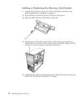
... the Memory Card Reader 1 Complete the procedures to the back of the memory card reader. 4 Push the memory card reader into the front of the chassis. 3 Attach the cable to remove the memory card reader, if necessary. See "Opening and Closing the PC" on the top of the memory card reader..., and then insert the short screw to secure the memory card reader to the chassis. 5 Complete the procedures to replace the front panel, replace the side panel, and close the PC. See "Removing the Memory Card Reader" on page 15...
... the Memory Card Reader 1 Complete the procedures to the back of the memory card reader. 4 Push the memory card reader into the front of the chassis. 3 Attach the cable to remove the memory card reader, if necessary. See "Opening and Closing the PC" on the top of the memory card reader..., and then insert the short screw to secure the memory card reader to the chassis. 5 Complete the procedures to replace the front panel, replace the side panel, and close the PC. See "Removing the Memory Card Reader" on page 15...

Upgrading and Servicing Guide
Page 21
Removing the Hard Disk Drive 1 Complete the procedures to prepare the PC to remove the side panel and to the chassis. 4 Push down the latch on its side. 3 Remove the two screws that secure the hard disk drive cage to remove the front panel. Upgrading and Servicing Guide 17 See "Opening and Closing the PC" on page 1. 2 Lay the computer gently on the side of the hard disk drive cage, and then slide the hard disk drive cage away from the bottom of the chassis as shown below.
Removing the Hard Disk Drive 1 Complete the procedures to prepare the PC to remove the side panel and to the chassis. 4 Push down the latch on its side. 3 Remove the two screws that secure the hard disk drive cage to remove the front panel. Upgrading and Servicing Guide 17 See "Opening and Closing the PC" on page 1. 2 Lay the computer gently on the side of the hard disk drive cage, and then slide the hard disk drive cage away from the bottom of the chassis as shown below.

Upgrading and Servicing Guide
Page 22
For Serial ATA hard disk drive cables, press the latch (5) (select models only) in the center of the chassis, and then remove the hard disk drive cables (1, 2). For most drive cables, use a gentle rocking motion to free the plug. 5 Lift the hard disk drive cage out of each plug (6), and pull the plug from the drive connector. 6 5 2 1 Disconnecting the Serial ATA hard disk drive cables MASTER SLAVE To CPU Disconnecting the Parallel ATA hard disk drive cables 18 Upgrading and Servicing Guide
For Serial ATA hard disk drive cables, press the latch (5) (select models only) in the center of the chassis, and then remove the hard disk drive cables (1, 2). For most drive cables, use a gentle rocking motion to free the plug. 5 Lift the hard disk drive cage out of each plug (6), and pull the plug from the drive connector. 6 5 2 1 Disconnecting the Serial ATA hard disk drive cables MASTER SLAVE To CPU Disconnecting the Parallel ATA hard disk drive cables 18 Upgrading and Servicing Guide

Upgrading and Servicing Guide
Page 24
3 Place the hard disk drive cage into place. 20 Upgrading and Servicing Guide The two screw holes on the hard disk drive cage (A) should be aligned with the holes on the chassis (B). A B 4 Align the four guides on the bottom of the hard disk drive cage with the screw holes on the back of the chassis, and then slide it down toward the bottom of the chassis until it locks into the chassis.
3 Place the hard disk drive cage into place. 20 Upgrading and Servicing Guide The two screw holes on the hard disk drive cage (A) should be aligned with the holes on the chassis (B). A B 4 Align the four guides on the bottom of the hard disk drive cage with the screw holes on the back of the chassis, and then slide it down toward the bottom of the chassis until it locks into the chassis.


