User Guide
Page 1
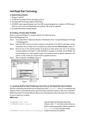
... than the total system memory 3. An SSD with SP1 2. Intel Rapid Start Technology enabled in sequence. At the diskpart prompt, type the following commands in BIOS Setup 4. Note: The commands for the exact disk number) (Create the primary store partition) Refer to Control Panel > System and Security > Administrative Tools > Computer Management...
... than the total system memory 3. An SSD with SP1 2. Intel Rapid Start Technology enabled in sequence. At the diskpart prompt, type the following commands in BIOS Setup 4. Note: The commands for the exact disk number) (Create the primary store partition) Refer to Control Panel > System and Security > Administrative Tools > Computer Management...
User Guide
Page 2
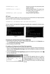
...data from the memory to the SSD after completing the commands above. When you execute the last command where you to enter the BIOS Setup program. Enabling the Intel Rapid Start Technology in the notification area. After the installation is volume of the selected disk and .... DISKPART>detail disk DISKPART>select volume X DISKPART>set Intel Rapid Start Technology to Enabled. 2. Refer to install. Save the settings and exit BIOS Setup. E. The Timer slider in the operating system, insert the motherboard driver disk, go to Application Software\Install Application Software, and select Intel...
...data from the memory to the SSD after completing the commands above. When you execute the last command where you to enter the BIOS Setup program. Enabling the Intel Rapid Start Technology in the notification area. After the installation is volume of the selected disk and .... DISKPART>detail disk DISKPART>select volume X DISKPART>set Intel Rapid Start Technology to Enabled. 2. Refer to install. Save the settings and exit BIOS Setup. E. The Timer slider in the operating system, insert the motherboard driver disk, go to Application Software\Install Application Software, and select Intel...
User Guide
Page 3
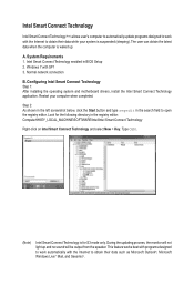
... on Intel Smart Connect Technology and select New > Key. Step 2: As shown in the left screenshot below, click the Start button and type regedit in BIOS Setup 2. Type OEM. (Note) Intel Smart Connect Technology is waked up and no sound will be output from the speaker. A. Intel Smart Connect Technology enabled...
... on Intel Smart Connect Technology and select New > Key. Step 2: As shown in the left screenshot below, click the Start button and type regedit in BIOS Setup 2. Type OEM. (Note) Intel Smart Connect Technology is waked up and no sound will be output from the speaker. A. Intel Smart Connect Technology enabled...
User Guide
Page 5
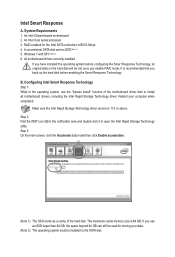
.... Step 2: Find the IRST icon in the notification area and double-click it to the SATA disk. Configuring Intel Smart Response Technology Step 1: While in BIOS Setup 4. Step 3: On the main screen, click the Accelerate button and then click Enable acceleration. All motherboard drivers correctly installed If you use the "Xpress...
.... Step 2: Find the IRST icon in the notification area and double-click it to the SATA disk. Configuring Intel Smart Response Technology Step 1: While in BIOS Setup 4. Step 3: On the main screen, click the Accelerate button and then click Enable acceleration. All motherboard drivers correctly installed If you use the "Xpress...
Manual
Page 3
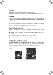
...Example: Documentation Classifications In order to their respective owners. Check your motherboard looks like this manual is protected by GIGABYTE without GIGABYTE's prior written permission. Changes to the specifications and features in this : "REV: X.X." For product-related information, ...check on our website at: http://www.gigabyte.com Identifying Your Motherboard Revision The revision number on your motherboard revision before updating motherboard BIOS, drivers, or when looking for technical information. Copyright © 2012 GIGA-BYTE...
...Example: Documentation Classifications In order to their respective owners. Check your motherboard looks like this manual is protected by GIGABYTE without GIGABYTE's prior written permission. Changes to the specifications and features in this : "REV: X.X." For product-related information, ...check on our website at: http://www.gigabyte.com Identifying Your Motherboard Revision The revision number on your motherboard revision before updating motherboard BIOS, drivers, or when looking for technical information. Copyright © 2012 GIGA-BYTE...
Manual
Page 4
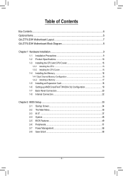
Table of Contents Box Contents...6 Optional Items...6 GA-Z77X-D3H Motherboard Layout 7 GA-Z77X-D3H Motherboard Block Diagram 8 Chapter 1 Hardware Installation 9 1-1 Installation Precautions 9 1-2 Product Specifications 10 1-3 Installing the CPU and CPU Cooler 13 ... Card 18 1-6 Setting up AMD CrossFireX™/NVIDIA SLI Configuration 19 1-7 Back Panel Connectors 20 1-8 Internal Connectors 22 Chapter 2 BIOS Setup 33 2-1 Startup Screen 34 2-2 The Main Menu 35 2-3 M.I.T...37 2-4 System...48 2-5 BIOS Features 49 2-6 Peripherals...51 2-7 Power Management 56 2-8 Save & Exit...58 - 4 -
Table of Contents Box Contents...6 Optional Items...6 GA-Z77X-D3H Motherboard Layout 7 GA-Z77X-D3H Motherboard Block Diagram 8 Chapter 1 Hardware Installation 9 1-1 Installation Precautions 9 1-2 Product Specifications 10 1-3 Installing the CPU and CPU Cooler 13 ... Card 18 1-6 Setting up AMD CrossFireX™/NVIDIA SLI Configuration 19 1-7 Back Panel Connectors 20 1-8 Internal Connectors 22 Chapter 2 BIOS Setup 33 2-1 Startup Screen 34 2-2 The Main Menu 35 2-3 M.I.T...37 2-4 System...48 2-5 BIOS Features 49 2-6 Peripherals...51 2-7 Power Management 56 2-8 Save & Exit...58 - 4 -
Manual
Page 5
... 60 3-4 Contact...61 3-5 System...61 3-6 Download Center 62 3-7 New Program 62 Chapter 4 Unique Features 63 4-1 Xpress Recovery2 63 4-2 BIOS Update Utilities 66 4-2-1 Updating the BIOS with the Q-Flash Utility 66 4-2-2 Updating the BIOS with the @BIOS Utility 69 4-3 EasyTune 6...70 4-4 Q-Share...71 4-5 eXtreme Hard Drive (X.H.D 72 4-6 Auto Green...73 4-7 Intel Rapid Start Technology 74...
... 60 3-4 Contact...61 3-5 System...61 3-6 Download Center 62 3-7 New Program 62 Chapter 4 Unique Features 63 4-1 Xpress Recovery2 63 4-2 BIOS Update Utilities 66 4-2-1 Updating the BIOS with the Q-Flash Utility 66 4-2-2 Updating the BIOS with the @BIOS Utility 69 4-3 EasyTune 6...70 4-4 Q-Share...71 4-5 eXtreme Hard Drive (X.H.D 72 4-6 Auto Green...73 4-7 Intel Rapid Start Technology 74...
Manual
Page 8
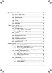
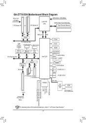
GA-Z77X-D3H Motherboard Block Diagram PCIe CLK (100 MHz) 1 PCI Express x16 or 2 PCI Express x8 LGA1155 CPU CPU CLK+/- (100 MHz) DDR3 1600/1333/1066 MHz ... LAN 88SE9172 PCI Express Bus x1 x1 VIA VL800 x1 Intel® Z77 x1 PCIe to PCI Bridge Switch x1 x4 D-Sub DVI-D HDMI Dual BIOS 3 SATA 3Gb/s 1 SATA 3Gb/s 1 mSATA or Switch 2 SATA 6Gb/s PCI Bus or 6 USB 2.0/1.1 3 PCI Express x1 1 PCI Express x4 CODEC 1 PCI 4 USB 3.0/2.0 LPC Bus iTE...
GA-Z77X-D3H Motherboard Block Diagram PCIe CLK (100 MHz) 1 PCI Express x16 or 2 PCI Express x8 LGA1155 CPU CPU CLK+/- (100 MHz) DDR3 1600/1333/1066 MHz ... LAN 88SE9172 PCI Express Bus x1 x1 VIA VL800 x1 Intel® Z77 x1 PCIe to PCI Bridge Switch x1 x4 D-Sub DVI-D HDMI Dual BIOS 3 SATA 3Gb/s 1 SATA 3Gb/s 1 mSATA or Switch 2 SATA 6Gb/s PCI Bus or 6 USB 2.0/1.1 3 PCI Express x1 1 PCI Express x4 CODEC 1 PCI 4 USB 3.0/2.0 LPC Bus iTE...
Manual
Page 12
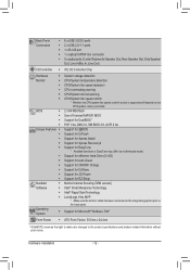
...; 2 x 64 Mbit flash ŠŠ Use of licensed AMI EFI BIOS ŠŠ Support for DualBIOS™ ŠŠ PnP 1.0a, DMI 2.0, SM BIOS 2.6, ACPI 2.0a Unique Features ŠŠ Support for @BIOS ŠŠ Support for Q-Flash ŠŠ Support for Xpress Install ŠŠ Support for Xpress Recovery2 Š Support for...
...; 2 x 64 Mbit flash ŠŠ Use of licensed AMI EFI BIOS ŠŠ Support for DualBIOS™ ŠŠ PnP 1.0a, DMI 2.0, SM BIOS 2.6, ACPI 2.0a Unique Features ŠŠ Support for @BIOS ŠŠ Support for Q-Flash ŠŠ Support for Xpress Install ŠŠ Support for Xpress Recovery2 Š Support for...
Manual
Page 16
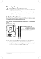
... memory mode will automatically detect the specifications and capacity of the same capacity, brand, speed, and chips be used . (Go to GIGABYTE's website for the latest supported memory speeds and memory modules.) •• Always turn off the computer and unplug the power cord from...only one DDR3 memory module is recommended that memory of the memory. Hardware Installation - 16 - DS/SS - - It is installed, the BIOS will double the original memory bandwidth. The four DDR3 memory sockets are unable to insert the memory, switch the direction. 1-4-1 Dual Channel Memory...
... memory mode will automatically detect the specifications and capacity of the same capacity, brand, speed, and chips be used . (Go to GIGABYTE's website for the latest supported memory speeds and memory modules.) •• Always turn off the computer and unplug the power cord from...only one DDR3 memory module is recommended that memory of the memory. Hardware Installation - 16 - DS/SS - - It is installed, the BIOS will double the original memory bandwidth. The four DDR3 memory sockets are unable to insert the memory, switch the direction. 1-4-1 Dual Channel Memory...
Manual
Page 18
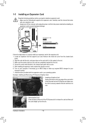
... expansion card in the slot. 3. Remove the metal slot cover from the power outlet before you begin to prevent hardware damage. If necessary, go to BIOS Setup to correctly install your expansion card(s). 7. Align the card with the slot, and press down on the card are completely inserted into the PCI...
... expansion card in the slot. 3. Remove the metal slot cover from the power outlet before you begin to prevent hardware damage. If necessary, go to BIOS Setup to correctly install your expansion card(s). 7. Align the card with the slot, and press down on the card are completely inserted into the PCI...
Manual
Page 21
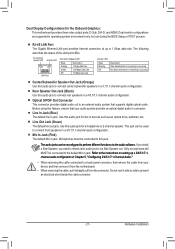
..., ensure that supports digital optical audio. This jack can be reconfigured to connect center/subwoofer speakers in operating system environment only, but not during the BIOS Setup or POST process. Before using this audio jack to perform different functions via the audio software. Use this audio jack to the default Mic...
..., ensure that supports digital optical audio. This jack can be reconfigured to connect center/subwoofer speakers in operating system environment only, but not during the BIOS Setup or POST process. Before using this audio jack to perform different functions via the audio software. Use this audio jack to the default Mic...
Manual
Page 24
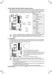
3/4) CPU_FAN/SYS_FAN1/SYS_FAN2/SYS_FAN3 (Fan Headers) All fan headers on the headers. 5) BAT (Battery) The battery provides power to keep the values (such as BIOS configurations, date, and time information) in the CMOS when the computer is turned off. When connecting a fan cable, be sure to the CPU or the ...
3/4) CPU_FAN/SYS_FAN1/SYS_FAN2/SYS_FAN3 (Fan Headers) All fan headers on the headers. 5) BAT (Battery) The battery provides power to keep the values (such as BIOS configurations, date, and time information) in the CMOS when the computer is turned off. When connecting a fan cable, be sure to the CPU or the ...
Manual
Page 26
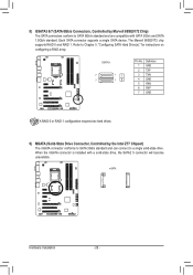
...GND 5 RXN 6 RXP 7 GND F_AUDIO(H) A RAID 0 or RAID 1 configuration reqF_uPiAreNsELtw(NoH)hard drives. DB_PORT BIOS Switcher (X58A-OC) 1 mSATA M_SATA Voltage measurement module(X58A-OC) PWM Switch (X58A-OC) ACPI_CPT (GA-IVB) DIP 1 23 1 DIP 1 23 1 DIP 1 23 1 DIP 1 23 PCIe power connector (SATA)(...X58A-OC) SMB_CPT (GA-IVB) nts(G1.Sniper 3) Hardware Installation BIOS Switcher (SW4) - 26 - GSATA3 G.QBOFM Pin No. 8) ...
...GND 5 RXN 6 RXP 7 GND F_AUDIO(H) A RAID 0 or RAID 1 configuration reqF_uPiAreNsELtw(NoH)hard drives. DB_PORT BIOS Switcher (X58A-OC) 1 mSATA M_SATA Voltage measurement module(X58A-OC) PWM Switch (X58A-OC) ACPI_CPT (GA-IVB) DIP 1 23 1 DIP 1 23 1 DIP 1 23 1 DIP 1 23 PCIe power connector (SATA)(...X58A-OC) SMB_CPT (GA-IVB) nts(G1.Sniper 3) Hardware Installation BIOS Switcher (SW4) - 26 - GSATA3 G.QBOFM Pin No. 8) ...
Manual
Page 27
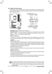
...(Speaker, Orange): Connects to the hard drive activity LED on the chassis front panel. When connecting your system using the power switch (refer to Chapter 2, "BIOS Setup," "Power Management," for information about beep codes. •• HD (Hard Drive Activity LED, Blue): Connects to the speaker on the chassis that ...The LED S0 On is on the chassis to indicate the problem. One single short beep will be heard if no problem is detected, the BIOS may issue beeps in S3/ S3/S4/S5 Off S4 sleep state or powered off your chassis front panel module to this header according to...
...(Speaker, Orange): Connects to the hard drive activity LED on the chassis front panel. When connecting your system using the power switch (refer to Chapter 2, "BIOS Setup," "Power Management," for information about beep codes. •• HD (Hard Drive Activity LED, Blue): Connects to the speaker on the chassis that ...The LED S0 On is on the chassis to indicate the problem. One single short beep will be heard if no problem is detected, the BIOS may issue beeps in S3/ S3/S4/S5 Off S4 sleep state or powered off your chassis front panel module to this header according to...
Manual
Page 28
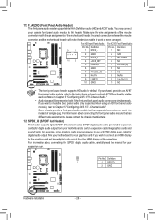
...S/PDIF digital audio cable (provided by default. ACPI_CPT (GA-IVB) SMB_CPT (GA-IVB) CLR_CMOS CI DIS_ME GP15_CPT (GA-IVB) Voltage measurement points(G1.Sniper 3) BIOS Switcher (SW4) 1 Pin No. 1 2 Definition SPDIFO GND XDP_CPU XDP_PCH (GA-IVB) Hardware Installation - 28 - 11) F_AUDIO (Front... 8 No Pin 8 No Pin 9 LINE2_L 9 Line Out (L) 10 GND 10 NC DIP 1 23 1 DIP 1 23 1 DIP 1 23 1 BIOS Switcher (X58A-OC) DB_PORT •• The front panel audio header supports HD audio by expansion cardPsC)Iefoprowdeigr citoanlnaecutodrio(SAoTuAt)p(Xu5t8Afr-oOmC) your chassis provides...
...S/PDIF digital audio cable (provided by default. ACPI_CPT (GA-IVB) SMB_CPT (GA-IVB) CLR_CMOS CI DIS_ME GP15_CPT (GA-IVB) Voltage measurement points(G1.Sniper 3) BIOS Switcher (SW4) 1 Pin No. 1 2 Definition SPDIFO GND XDP_CPU XDP_PCH (GA-IVB) Hardware Installation - 28 - 11) F_AUDIO (Front... 8 No Pin 8 No Pin 9 LINE2_L 9 Line Out (L) 10 GND 10 NC DIP 1 23 1 DIP 1 23 1 DIP 1 23 1 BIOS Switcher (X58A-OC) DB_PORT •• The front panel audio header supports HD audio by expansion cardPsC)Iefoprowdeigr citoanlnaecutodrio(SAoTuAt)p(Xu5t8Afr-oOmC) your chassis provides...
Manual
Page 29
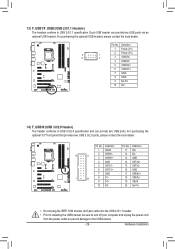
...(5V) 2 Power (5V) 9 1 10 2 3 USB DX- 4 USB DY- 5 USB DX+ 6 USB DY+ 7 GND 8 GND 9 No Pin 10 NC DIP 1 23 1 PWM Switch (X58A-OC) BIOS Switcher (X58A-OC) 1 M_SATA DIP 1 23 PCIe power connector (SATA)(X58A-OC) DIP 1 23 1 DIP 1 23 1 Voltage measurement module(X58A-OC) 14) F_USB30 (USB 3.0/2.0 Header... USB 3.0/2.0 ports, please contact the local dealer. For purchasing the optional USB bracket, please contact the local dealer. F_PANEL (H61M-D2) ACPI_CPT (GA-IVB) SMB_CPT (GA-IVB) 13) F_USB1/F_USB2 (USB 2.0/1.1 Headers) The headers conform to USB 2.0/1.1 specification.
...(5V) 2 Power (5V) 9 1 10 2 3 USB DX- 4 USB DY- 5 USB DX+ 6 USB DY+ 7 GND 8 GND 9 No Pin 10 NC DIP 1 23 1 PWM Switch (X58A-OC) BIOS Switcher (X58A-OC) 1 M_SATA DIP 1 23 PCIe power connector (SATA)(X58A-OC) DIP 1 23 1 DIP 1 23 1 Voltage measurement module(X58A-OC) 14) F_USB30 (USB 3.0/2.0 Header... USB 3.0/2.0 ports, please contact the local dealer. For purchasing the optional USB bracket, please contact the local dealer. F_PANEL (H61M-D2) ACPI_CPT (GA-IVB) SMB_CPT (GA-IVB) 13) F_USB1/F_USB2 (USB 2.0/1.1 Headers) The headers conform to USB 2.0/1.1 specification.
Manual
Page 30
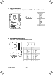
DB_PORT BIOS Switc 1 1 19 TPM w/housing 20 1 Voltage measurement module(X58A-OC) 2 Pin No. 1 2 3 4 5 6 7 8 9 10 Definition Pin No. Definition 1 NDCD- 2 NSIN 1 3 NSOUT 2 4 NDTR- 5 GND 6 NDSR- 7 NRTS- 8 NCTS- 9 ... 14 ID LRESET 15 SB3V NC 16 SERIRQ LAD3 17 GND LAD2 18 NC VCC3 19 NC LAD1 20 SUSCLK Voltage measurement points(G1.Sniper 3) BIOS Switcher (SW4) PWM Swi DIP 1 23 DIP Hardware Installation - 30 -
DB_PORT BIOS Switc 1 1 19 TPM w/housing 20 1 Voltage measurement module(X58A-OC) 2 Pin No. 1 2 3 4 5 6 7 8 9 10 Definition Pin No. Definition 1 NDCD- 2 NSIN 1 3 NSOUT 2 4 NDTR- 5 GND 6 NDSR- 7 NRTS- 8 NCTS- 9 ... 14 ID LRESET 15 SB3V NC 16 SERIRQ LAD3 17 GND LAD2 18 NC VCC3 19 NC LAD1 20 SUSCLK Voltage measurement points(G1.Sniper 3) BIOS Switcher (SW4) PWM Swi DIP 1 23 DIP Hardware Installation - 30 -
Manual
Page 31
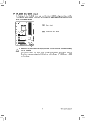
... object like a screwdriver to clear the CMOS values (e.g. 17) CLR_CMOS (Clear CMOS Jumper) Use this jumper to touch the two pins for BIOS configurations). - 31 - Open: Normal Short: Clear CMOS Values •• Always turn off your computer and unplug the power cord from the...power outlet before clearing the CMOS values. •• After system restart, go to BIOS Setup to load factory defaults (select Load Optimized Defaults) or manually configure the BIOS settings (refer to factory defaults. date information and BIOS configurations) and reset the CMOS values to Chapter...
... object like a screwdriver to clear the CMOS values (e.g. 17) CLR_CMOS (Clear CMOS Jumper) Use this jumper to touch the two pins for BIOS configurations). - 31 - Open: Normal Short: Clear CMOS Values •• Always turn off your computer and unplug the power cord from the...power outlet before clearing the CMOS values. •• After system restart, go to BIOS Setup to load factory defaults (select Load Optimized Defaults) or manually configure the BIOS settings (refer to factory defaults. date information and BIOS configurations) and reset the CMOS values to Chapter...
Manual
Page 33
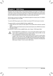
... the Internet and updates the BIOS. Its major functions include conducting the Power-On Self-Test (POST) during the POST when the power is turned off, the battery on . To upgrade the BIOS, use either the GIGABYTE Q-Flash or @BIOS utility. •• Q-Flash allows the user to quickly ...and easily upgrade or back up BIOS without entering the operating system. •• @BIOS is recommended that allows the user to modify basic system...
... the Internet and updates the BIOS. Its major functions include conducting the Power-On Self-Test (POST) during the POST when the power is turned off, the battery on . To upgrade the BIOS, use either the GIGABYTE Q-Flash or @BIOS utility. •• Q-Flash allows the user to quickly ...and easily upgrade or back up BIOS without entering the operating system. •• @BIOS is recommended that allows the user to modify basic system...


