
Manual
Page 1
...Chapter 5, "Installing the SATA RAID/AHCI Driver and Operating System." ) Step 3: Install the motherboard drivers and the X.H.D utiltiy After installing the operating system, insert the motherboard driver disk. The following procedure details the steps to set up a RAID-ready system and configure...be recognized during the Windows setup process. (For more details, refer to enable RAID for complex and time-consuming configurations. Using GIGABYTE eXtreme Hard Drive (X.H.D) Instructions:(Note 2) Before launching X.H.D, make sure the newly added harddrive has equal or greater capacity than or...
...Chapter 5, "Installing the SATA RAID/AHCI Driver and Operating System." ) Step 3: Install the motherboard drivers and the X.H.D utiltiy After installing the operating system, insert the motherboard driver disk. The following procedure details the steps to set up a RAID-ready system and configure...be recognized during the Windows setup process. (For more details, refer to enable RAID for complex and time-consuming configurations. Using GIGABYTE eXtreme Hard Drive (X.H.D) Instructions:(Note 2) Before launching X.H.D, make sure the newly added harddrive has equal or greater capacity than or...
Manual
Page 1
GA-P55-USB3 LGA1156 socket motherboard for Intel® Core™ i7 processor family/ Intel® Core™ i5 processor family User's Manual Rev. 1001 12ME-P55USB3-1001R
GA-P55-USB3 LGA1156 socket motherboard for Intel® Core™ i7 processor family/ Intel® Core™ i5 processor family User's Manual Rev. 1001 12ME-P55USB3-1001R

Manual
Page 2
Motherboard GA-P55-USB3 Dec. 24, 2009 Motherboard GA-P55-USB3 Dec. 24, 2009
Motherboard GA-P55-USB3 Dec. 24, 2009 Motherboard GA-P55-USB3 Dec. 24, 2009
Manual
Page 3
...of the product, read the Quick Installation Guide included with the product. Check your motherboard looks like this manual may be reproduced, copied, translated, transmitted, or published in the use GIGABYTE's unique features, read the User's Manual. All rights reserved. For instructions on how... In order to use of this : "REV: X.X." For product-related information, check on our website at: http://www.gigabyte.com.tw Identifying Your Motherboard Revision The revision number on our website. Copyright © 2009 GIGA-BYTE TECHNOLOGY CO., LTD. No part of this manual...
...of the product, read the Quick Installation Guide included with the product. Check your motherboard looks like this manual may be reproduced, copied, translated, transmitted, or published in the use GIGABYTE's unique features, read the User's Manual. All rights reserved. For instructions on how... In order to use of this : "REV: X.X." For product-related information, check on our website at: http://www.gigabyte.com.tw Identifying Your Motherboard Revision The revision number on our website. Copyright © 2009 GIGA-BYTE TECHNOLOGY CO., LTD. No part of this manual...
Manual
Page 4
Table of Contents Box Contents...6 Optional Items...6 GA-P55-USB3 Motherboard Layout 7 GA-P55-USB3 Motherboard Block Diagram 8 Chapter 1 Hardware Installation 9 1-1 Installation Precautions 9 1-2 Product Specifications 10 1-3 Installing the CPU and CPU Cooler 13 1-3-1 Installing the CPU 13 1-3-2 Installing the CPU Cooler ...
Table of Contents Box Contents...6 Optional Items...6 GA-P55-USB3 Motherboard Layout 7 GA-P55-USB3 Motherboard Block Diagram 8 Chapter 1 Hardware Installation 9 1-1 Installation Precautions 9 1-2 Product Specifications 10 1-3 Installing the CPU and CPU Cooler 13 1-3-1 Installing the CPU 13 1-3-2 Installing the CPU Cooler ...
Manual
Page 6
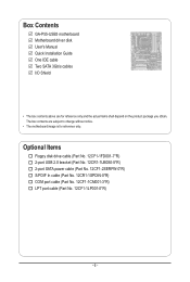
.... 12CF1-2SERPW-0*R) S/PDIF In cable (Part No. 12CR1-1SPDIN-0*R) COM port cable (Part No. 12CF1-1CM001-3*R) LPT port cable (Part No. 12CF1-1LP001-0*R) - 6 - Box Contents GA-P55-USB3 motherboard Motherboard driver disk User's Manual Quick Installation Guide One IDE cable Two SATA 3Gb/s cables I/O Shield • The box contents above are subject to change without...
.... 12CF1-2SERPW-0*R) S/PDIF In cable (Part No. 12CR1-1SPDIN-0*R) COM port cable (Part No. 12CF1-1CM001-3*R) LPT port cable (Part No. 12CF1-1LP001-0*R) - 6 - Box Contents GA-P55-USB3 motherboard Motherboard driver disk User's Manual Quick Installation Guide One IDE cable Two SATA 3Gb/s cables I/O Shield • The box contents above are subject to change without...

Manual
Page 7
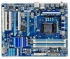
For a longer expansion card, use other expansion slots. - 7 - GA-P55-USB3 Motherboard Layout KB_USBj R_SPDIF CPU_FAN ATX_12V_2X4 R_USB_2 R_USB_1 R_USB30 LGA1156 PWR_FAN PHASE LED ATX USB_LAN NEC AUDIO F_AUDIO RTL8111D PCIEX16 GA-P55-USB3 PCIEX1_1 (Note) SYS_FAN1 IDE SYS_FAN2 DDR3_2 DDR3_1 DDR3_4 DDR3_3 PCIEX1_2 BAT CODEC PCI1 PCIEX4_X1 GIGABYTE SATA2 Intel® P55/H55 GSATA2_6 GSATA2_7 CD_IN SPDIF_I SPDIF_O IT8720...
For a longer expansion card, use other expansion slots. - 7 - GA-P55-USB3 Motherboard Layout KB_USBj R_SPDIF CPU_FAN ATX_12V_2X4 R_USB_2 R_USB_1 R_USB30 LGA1156 PWR_FAN PHASE LED ATX USB_LAN NEC AUDIO F_AUDIO RTL8111D PCIEX16 GA-P55-USB3 PCIEX1_1 (Note) SYS_FAN1 IDE SYS_FAN2 DDR3_2 DDR3_1 DDR3_4 DDR3_3 PCIEX1_2 BAT CODEC PCI1 PCIEX4_X1 GIGABYTE SATA2 Intel® P55/H55 GSATA2_6 GSATA2_7 CD_IN SPDIF_I SPDIF_O IT8720...

Manual
Page 8
j Only for H55 Chipset. GA-P55-USB3 Motherboard Block Diagram PCIe CLK (100 MHz) 1 PCI Express x16 LGA1156 CPU CPU CLK+/- (133 MHz) DDR3 2200/1333/1066/800 MHz Dual Channel... (PCIEX1_2) 2 USB 3.0 x1 x4j/X1k Switchj NEC PCI Express Bus Dual BIOS Intel® P55/H55 6 SATA 3Gb/s x1 14 USB 2.0/1.1j (Note) 2 SATA 3Gb/s ATA-133/100/66/33 IDE Channel GIGABYTE SATA2 12 USB 2.0/1.1k (Note) PCI Bus LPC Bus Floppy CODEC IT8720 COM Port PS/2 KB... Out Line In S/PDIF In S/PDIF Out 3 PCI PCI CLK (33 MHz) (Note) Two share the same ports with USB 3.0. - 8 - k Only for P55 Chipset.
j Only for H55 Chipset. GA-P55-USB3 Motherboard Block Diagram PCIe CLK (100 MHz) 1 PCI Express x16 LGA1156 CPU CPU CLK+/- (133 MHz) DDR3 2200/1333/1066/800 MHz Dual Channel... (PCIEX1_2) 2 USB 3.0 x1 x4j/X1k Switchj NEC PCI Express Bus Dual BIOS Intel® P55/H55 6 SATA 3Gb/s x1 14 USB 2.0/1.1j (Note) 2 SATA 3Gb/s ATA-133/100/66/33 IDE Channel GIGABYTE SATA2 12 USB 2.0/1.1k (Note) PCI Bus LPC Bus Floppy CODEC IT8720 COM Port PS/2 KB... Out Line In S/PDIF In S/PDIF Out 3 PCI PCI CLK (33 MHz) (Note) Two share the same ports with USB 3.0. - 8 - k Only for P55 Chipset.
Manual
Page 9
.... • It is best to the use of your dealer. If you are connected tightly and securely. • When handling the motherboard, avoid touching any installation steps or have it on top of an antistatic pad or within the computer casing. • Do not place... not place the computer system in a high-temperature environment. • Turning on the computer power during the installation process can become damaged as a motherboard, CPU or memory. Prior to installation, carefully read the user's manual and follow these procedures: • Prior to installation, do not have an...
.... • It is best to the use of your dealer. If you are connected tightly and securely. • When handling the motherboard, avoid touching any installation steps or have it on top of an antistatic pad or within the computer casing. • Do not place... not place the computer system in a high-temperature environment. • Turning on the computer power during the installation process can become damaged as a motherboard, CPU or memory. Prior to installation, carefully read the user's manual and follow these procedures: • Prior to installation, do not have an...
Manual
Page 12
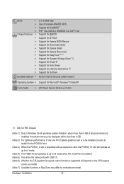
... Internet Security (OEM version) Operating System w Support for Microsoft® Windows® 7/Vista/XP Form Factor w ATX Form Factor; 30.5cm x 24.4cm j Only for P55 Chipset. (Note 1) Due to Windows 32-bit operating system limitation, when more than 4 GB of physical memory is installed, the actual memory size displayed will... CPU/system fan speed control function is supported will depend on the CPU/system cooler you install. (Note 7) Available functions in EasyTune may differ by motherboard model. Hardware Installation - 12 -
... Internet Security (OEM version) Operating System w Support for Microsoft® Windows® 7/Vista/XP Form Factor w ATX Form Factor; 30.5cm x 24.4cm j Only for P55 Chipset. (Note 1) Due to Windows 32-bit operating system limitation, when more than 4 GB of physical memory is installed, the actual memory size displayed will... CPU/system fan speed control function is supported will depend on the CPU/system cooler you install. (Note 7) Available functions in EasyTune may differ by motherboard model. Hardware Installation - 12 -
Manual
Page 13
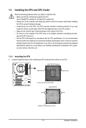
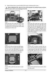
... the CPU. • Do not turn on the computer if the CPU cooler is not recommended that the motherboard supports the CPU. (Go to GIGABYTE's website for the peripherals. Locate the alignment keys on the motherboard CPU socket and the notches on the CPU - 13 - LGA1156 CPU Socket Alignment Key Alignment Key Pin...
... the CPU. • Do not turn on the computer if the CPU cooler is not recommended that the motherboard supports the CPU. (Go to GIGABYTE's website for the peripherals. Locate the alignment keys on the motherboard CPU socket and the notches on the CPU - 13 - LGA1156 CPU Socket Alignment Key Alignment Key Pin...
Manual
Page 14
B. Step 5: Push the CPU socket lever back into the motherboard CPU socket. Align the CPU pin one marking (triangle) with the socket alignment keys) and gently insert the CPU into position. Before installing the CPU, ...
B. Step 5: Push the CPU socket lever back into the motherboard CPU socket. Align the CPU pin one marking (triangle) with the socket alignment keys) and gently insert the CPU into position. Before installing the CPU, ...
Manual
Page 15
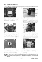
... on installing the cooler.) Step 5: After the installation, check the back of the CPU cooler to the CPU fan header (CPU_FAN) on the motherboard. Hardware Installation If the push pin is inserted as the example cooler.) Step 1: Apply an even and thin layer of thermal grease on the ... removing the CPU cooler may adhere to the CPU. 1-3-2 Installing the CPU Cooler Follow the steps below to correctly install the CPU cooler on the motherboard. (The following procedure uses Intel® boxed cooler as the picture above shows, the installation is to install.) Step 3: Place the cooler atop...
... on installing the cooler.) Step 5: After the installation, check the back of the CPU cooler to the CPU fan header (CPU_FAN) on the motherboard. Hardware Installation If the push pin is inserted as the example cooler.) Step 1: Apply an even and thin layer of thermal grease on the ... removing the CPU cooler may adhere to the CPU. 1-3-2 Installing the CPU Cooler Follow the steps below to correctly install the CPU cooler on the motherboard. (The following procedure uses Intel® boxed cooler as the picture above shows, the installation is to install.) Step 3: Place the cooler atop...
Manual
Page 16
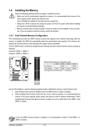
...1: DDR3_3, DDR3_4 Dual Channel Memory Configurations Table DDR3_2 DDR3_1 DDR3_4 DDR3_3 Two Modules - - Dual Channel mode cannot be sure to GIGABYTE's website for optimum performance. 1-4 Installing the Memory Read the following guidelines before you are divided into two channels and each channel ...sockets as following guidelines before installing the memory to insert the memory, switch the direction. 1-4-1 Dual Channel Memory Configuration This motherboard provides four DDR3 memory sockets and supports Dual Channel Technology. If you begin to install the memory: • Make ...
...1: DDR3_3, DDR3_4 Dual Channel Memory Configurations Table DDR3_2 DDR3_1 DDR3_4 DDR3_3 Two Modules - - Dual Channel mode cannot be sure to GIGABYTE's website for optimum performance. 1-4 Installing the Memory Read the following guidelines before you are divided into two channels and each channel ...sockets as following guidelines before installing the memory to insert the memory, switch the direction. 1-4-1 Dual Channel Memory Configuration This motherboard provides four DDR3 memory sockets and supports Dual Channel Technology. If you begin to install the memory: • Make ...
Manual
Page 17
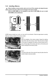
..., make sure to turn off the computer and unplug the power cord from the power outlet to prevent damage to install DDR3 DIMMs on this motherboard.
..., make sure to turn off the computer and unplug the power cord from the power outlet to prevent damage to install DDR3 DIMMs on this motherboard.
Manual
Page 18
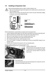
... to make any required BIOS changes for your expansion card(s). 7. If necessary, go to BIOS Setup to install an expansion card: • Make sure the motherboard supports the expansion card. 1-5 Installing an Expansion Card Read the following guidelines before installing an expansion card to release the card and then pull the...
... to make any required BIOS changes for your expansion card(s). 7. If necessary, go to BIOS Setup to install an expansion card: • Make sure the motherboard supports the expansion card. 1-5 Installing an Expansion Card Read the following guidelines before installing an expansion card to release the card and then pull the...
Manual
Page 19
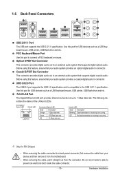
...port for USB devices such as a USB keyboard/mouse, USB printer, USB flash drive and etc. Hardware Installation Before using this port for P55 Chipset. • When removing the cable connected to a back panel connector, first remove the cable from the connector. Do not rock it...j USB 2.0/1.1 Port The USB port supports the USB 2.0/1.1 specification. Before using this feature, ensure that your device and then remove it from the motherboard. • When removing the cable, pull it side to side to 1 Gbps data rate. Connection/ Speed LED Activity LED LAN Port Connection/Speed...
...port for USB devices such as a USB keyboard/mouse, USB printer, USB flash drive and etc. Hardware Installation Before using this port for P55 Chipset. • When removing the cable connected to a back panel connector, first remove the cable from the connector. Do not rock it...j USB 2.0/1.1 Port The USB port supports the USB 2.0/1.1 specification. Before using this feature, ensure that your device and then remove it from the motherboard. • When removing the cable, pull it side to side to 1 Gbps data rate. Connection/ Speed LED Activity LED LAN Port Connection/Speed...
Manual
Page 21
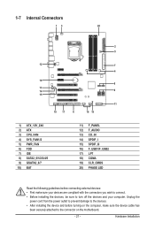
...) CD_IN 14) SPDIF_I 15) SPDIF_O 16) F_USB1/F_USB2 17) LPT 18) COMA 19) CLR_CMOS 20) PHASE LED Read the following guidelines before turning on the motherboard. - 21 - Hardware Installation Unplug the power cord from the power outlet to prevent damage to the devices. • After installing the device and before connecting...
...) CD_IN 14) SPDIF_I 15) SPDIF_O 16) F_USB1/F_USB2 17) LPT 18) COMA 19) CLR_CMOS 20) PHASE LED Read the following guidelines before turning on the motherboard. - 21 - Hardware Installation Unplug the power cord from the power outlet to prevent damage to the devices. • After installing the device and before connecting...
Manual
Page 22
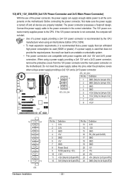
... using an Intel Extreme Edition CPU (130W). • To meet expansion requirements, it is turned off and all the components on the motherboard. Do not insert the power supply cables into pins under the protective covers when using a power supply providing a 2x4 12V and a 2x12... power connector, remove the protective covers from the 12V power connector and the main power connector on the motherboard. The power connector possesses a foolproof design. Connect the power supply cable to the CPU. 1/2) ATX_12V_2X4/ATX (2x4 12V Power Connector and 2x12...
... using an Intel Extreme Edition CPU (130W). • To meet expansion requirements, it is turned off and all the components on the motherboard. Do not insert the power supply cables into pins under the protective covers when using a power supply providing a 2x4 12V and a 2x12... power connector, remove the protective covers from the 12V power connector and the main power connector on the motherboard. The power connector possesses a foolproof design. Connect the power supply cable to the CPU. 1/2) ATX_12V_2X4/ATX (2x4 12V Power Connector and 2x12...
Manual
Page 23
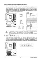
When connecting a fan cable, be sure to locate pin 1 of a CPU fan with fan speed control design. The motherboard supports CPU fan speed control, which requires the use of the connector and the floppy disk drive cable. Definition 1 GND 2 +12V 3 Sense &#... design. For purchasing the optional floppy disk drive cable, please contact the local dealer. 33 1 34 2 - 23 - 3/4/5) CPU_FAN/SYS_FAN1/SYS_FAN2/PWR_FAN (Fan Headers) The motherboard has a 4-pin CPU fan header (CPU_FAN), a 4-pin (SYS_FAN2) and two 3-pin (SYS_ FAN1) system fan headers, and a 3-pin power fan header (PWR_FAN). ...
When connecting a fan cable, be sure to locate pin 1 of a CPU fan with fan speed control design. The motherboard supports CPU fan speed control, which requires the use of the connector and the floppy disk drive cable. Definition 1 GND 2 +12V 3 Sense &#... design. For purchasing the optional floppy disk drive cable, please contact the local dealer. 33 1 34 2 - 23 - 3/4/5) CPU_FAN/SYS_FAN1/SYS_FAN2/PWR_FAN (Fan Headers) The motherboard has a 4-pin CPU fan header (CPU_FAN), a 4-pin (SYS_FAN2) and two 3-pin (SYS_ FAN1) system fan headers, and a 3-pin power fan header (PWR_FAN). ...


