
Manual
Page 1
... the hard drive may not be able to enhance your hard drive read/write performance without the need for the Intel SATA controllers. Using GIGABYTE eXtreme Hard Drive (X.H.D) Instructions:(Note 2) Before launching X.H.D, make sure the new drive is added. B. Setting Up a RAID-Ready System Step... 1: Configure the system BIOS Enter the system BIOS Setup program, set up all motherboard drivers, including the X.H.D utility. Or you can quickly configure a RAIDready system for RAID 0. You can go to the Application Software screen ...
... the hard drive may not be able to enhance your hard drive read/write performance without the need for the Intel SATA controllers. Using GIGABYTE eXtreme Hard Drive (X.H.D) Instructions:(Note 2) Before launching X.H.D, make sure the new drive is added. B. Setting Up a RAID-Ready System Step... 1: Configure the system BIOS Enter the system BIOS Setup program, set up all motherboard drivers, including the X.H.D utility. Or you can quickly configure a RAIDready system for RAID 0. You can go to the Application Software screen ...
Manual
Page 1
GA-P55-USB3 LGA1156 socket motherboard for Intel® Core™ i7 processor family/ Intel® Core™ i5 processor family User's Manual Rev. 1001 12ME-P55USB3-1001R
GA-P55-USB3 LGA1156 socket motherboard for Intel® Core™ i7 processor family/ Intel® Core™ i5 processor family User's Manual Rev. 1001 12ME-P55USB3-1001R

Manual
Page 2
Motherboard GA-P55-USB3 Dec. 24, 2009 Motherboard GA-P55-USB3 Dec. 24, 2009
Motherboard GA-P55-USB3 Dec. 24, 2009 Motherboard GA-P55-USB3 Dec. 24, 2009
Manual
Page 3
... any means without prior notice. Copyright © 2009 GIGA-BYTE TECHNOLOGY CO., LTD. For product-related information, check on our website at: http://www.gigabyte.com.tw Identifying Your Motherboard Revision The revision number on our website. For detailed product information, carefully read or download the information on/from the Support&Downloads...
... any means without prior notice. Copyright © 2009 GIGA-BYTE TECHNOLOGY CO., LTD. For product-related information, check on our website at: http://www.gigabyte.com.tw Identifying Your Motherboard Revision The revision number on our website. For detailed product information, carefully read or download the information on/from the Support&Downloads...
Manual
Page 4
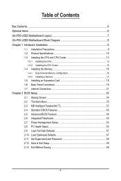
Table of Contents Box Contents...6 Optional Items...6 GA-P55-USB3 Motherboard Layout 7 GA-P55-USB3 Motherboard Block Diagram 8 Chapter 1 Hardware Installation 9 1-1 Installation Precautions 9 1-2 Product Specifications 10 1-3 Installing the CPU and CPU Cooler 13 1-3-1 Installing the CPU 13 1-3-2 Installing the CPU Cooler ...
Table of Contents Box Contents...6 Optional Items...6 GA-P55-USB3 Motherboard Layout 7 GA-P55-USB3 Motherboard Block Diagram 8 Chapter 1 Hardware Installation 9 1-1 Installation Precautions 9 1-2 Product Specifications 10 1-3 Installing the CPU and CPU Cooler 13 1-3-1 Installing the CPU 13 1-3-2 Installing the CPU Cooler ...
Manual
Page 6
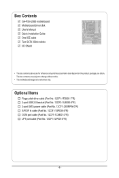
...(Part No. 12CR1-1SPDIN-0*R) COM port cable (Part No. 12CF1-1CM001-3*R) LPT port cable (Part No. 12CF1-1LP001-0*R) - 6 - Box Contents GA-P55-USB3 motherboard Motherboard driver disk User's Manual Quick Installation Guide One IDE cable Two SATA 3Gb/s cables I/O Shield • The box contents above are subject to change without... notice. • The motherboard image is for reference only and the actual items shall depend on the product package you obtain. The box contents are for reference only...
...(Part No. 12CR1-1SPDIN-0*R) COM port cable (Part No. 12CF1-1CM001-3*R) LPT port cable (Part No. 12CF1-1LP001-0*R) - 6 - Box Contents GA-P55-USB3 motherboard Motherboard driver disk User's Manual Quick Installation Guide One IDE cable Two SATA 3Gb/s cables I/O Shield • The box contents above are subject to change without... notice. • The motherboard image is for reference only and the actual items shall depend on the product package you obtain. The box contents are for reference only...

Manual
Page 7
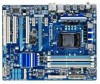
GA-P55-USB3 Motherboard Layout KB_USBj R_SPDIF CPU_FAN ATX_12V_2X4 R_USB_2 R_USB_1 R_USB30 LGA1156 PWR_FAN PHASE LED ATX USB_LAN NEC AUDIO F_AUDIO RTL8111D PCIEX16 GA-P55-USB3 PCIEX1_1 (Note) SYS_FAN1 IDE SYS_FAN2 DDR3_2 DDR3_1 DDR3_4 DDR3_3 PCIEX1_2 BAT CODEC PCI1 PCIEX4_X1 GIGABYTE SATA2 Intel® P55/H55 GSATA2_6 GSATA2_7 CD_IN SPDIF_I SPDIF_O IT8720 PCI2 PCI3 LPT COMA B_BIOS FDD F_USB2 M_BIOS...
GA-P55-USB3 Motherboard Layout KB_USBj R_SPDIF CPU_FAN ATX_12V_2X4 R_USB_2 R_USB_1 R_USB30 LGA1156 PWR_FAN PHASE LED ATX USB_LAN NEC AUDIO F_AUDIO RTL8111D PCIEX16 GA-P55-USB3 PCIEX1_1 (Note) SYS_FAN1 IDE SYS_FAN2 DDR3_2 DDR3_1 DDR3_4 DDR3_3 PCIEX1_2 BAT CODEC PCI1 PCIEX4_X1 GIGABYTE SATA2 Intel® P55/H55 GSATA2_6 GSATA2_7 CD_IN SPDIF_I SPDIF_O IT8720 PCI2 PCI3 LPT COMA B_BIOS FDD F_USB2 M_BIOS...

Manual
Page 8
k Only for P55 Chipset. GA-P55-USB3 Motherboard Block Diagram PCIe CLK (100 MHz) 1 PCI Express x16 LGA1156 CPU CPU CLK+/- (133 MHz) DDR3 2200/1333/1066/800 MHz Dual Channel Memory PCI ... Express x1 (PCIEX1_2) 2 USB 3.0 x1 x4j/X1k Switchj NEC PCI Express Bus Dual BIOS Intel® P55/H55 6 SATA 3Gb/s x1 14 USB 2.0/1.1j (Note) 2 SATA 3Gb/s ATA-133/100/66/33 IDE Channel GIGABYTE SATA2 12 USB 2.0/1.1k (Note) PCI Bus LPC Bus Floppy CODEC IT8720 COM Port PS/2 KB/Mouse...
k Only for P55 Chipset. GA-P55-USB3 Motherboard Block Diagram PCIe CLK (100 MHz) 1 PCI Express x16 LGA1156 CPU CPU CLK+/- (133 MHz) DDR3 2200/1333/1066/800 MHz Dual Channel Memory PCI ... Express x1 (PCIEX1_2) 2 USB 3.0 x1 x4j/X1k Switchj NEC PCI Express Bus Dual BIOS Intel® P55/H55 6 SATA 3Gb/s x1 14 USB 2.0/1.1j (Note) 2 SATA 3Gb/s ATA-133/100/66/33 IDE Channel GIGABYTE SATA2 12 USB 2.0/1.1k (Note) PCI Bus LPC Bus Floppy CODEC IT8720 COM Port PS/2 KB/Mouse...
Manual
Page 9
... electrostatic discharge (ESD) wrist strap when handling electronic com- If you are connected tightly and securely. • When handling the motherboard, avoid touching any installation steps or have it on top of the product, please consult a certified computer technician. - 9 -... Hardware Installation Chapter 1 Hardware Installation 1-1 Installation Precautions The motherboard contains numerous delicate electronic circuits and components which can lead to damage to system components as well as physical harm to the ...
... electrostatic discharge (ESD) wrist strap when handling electronic com- If you are connected tightly and securely. • When handling the motherboard, avoid touching any installation steps or have it on top of the product, please consult a certified computer technician. - 9 -... Hardware Installation Chapter 1 Hardware Installation 1-1 Installation Precautions The motherboard contains numerous delicate electronic circuits and components which can lead to damage to system components as well as physical harm to the ...
Manual
Page 12
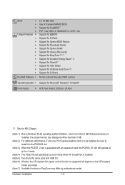
... Internet Security (OEM version) Operating System w Support for Microsoft® Windows® 7/Vista/XP Form Factor w ATX Form Factor; 30.5cm x 24.4cm j Only for P55 Chipset. (Note 1) Due to Windows 32-bit operating system limitation, when more than 4 GB of physical memory is installed, the actual memory size displayed will... CPU/system fan speed control function is supported will depend on the CPU/system cooler you install. (Note 7) Available functions in EasyTune may differ by motherboard model. Hardware Installation - 12 -
... Internet Security (OEM version) Operating System w Support for Microsoft® Windows® 7/Vista/XP Form Factor w ATX Form Factor; 30.5cm x 24.4cm j Only for P55 Chipset. (Note 1) Due to Windows 32-bit operating system limitation, when more than 4 GB of physical memory is installed, the actual memory size displayed will... CPU/system fan speed control function is supported will depend on the CPU/system cooler you install. (Note 7) Available functions in EasyTune may differ by motherboard model. Hardware Installation - 12 -
Manual
Page 13
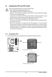
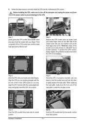
...One Corner of the CPU. • Do not turn on the computer if the CPU cooler is not recommended that the motherboard supports the CPU. (Go to GIGABYTE's website for the peripherals. The CPU cannot be set the frequency beyond hardware specifications since it does not meet the standard ... may occur. • Set the CPU host frequency in accordance with the CPU specifications. age of the CPU. Locate the alignment keys on the motherboard CPU socket and the notches on the CPU - 13 - It is not installed, otherwise overheating and dam- 1-3 Installing the CPU and CPU Cooler...
...One Corner of the CPU. • Do not turn on the computer if the CPU cooler is not recommended that the motherboard supports the CPU. (Go to GIGABYTE's website for the peripherals. The CPU cannot be set the frequency beyond hardware specifications since it does not meet the standard ... may occur. • Set the CPU host frequency in accordance with the CPU specifications. age of the CPU. Locate the alignment keys on the motherboard CPU socket and the notches on the CPU - 13 - It is not installed, otherwise overheating and dam- 1-3 Installing the CPU and CPU Cooler...
Manual
Page 14
... cord from the socket with the pin one hand to hold the socket lever and use the other to correctly install the CPU into the motherboard CPU socket. Hardware Installation - 14 - Before installing the CPU, make sure the front end of the socket cover and remove it. (DO NOT touch socket...
... cord from the socket with the pin one hand to hold the socket lever and use the other to correctly install the CPU into the motherboard CPU socket. Hardware Installation - 14 - Before installing the CPU, make sure the front end of the socket cover and remove it. (DO NOT touch socket...
Manual
Page 15
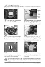
... may damage the CPU. - 15 - Step 6: Finally, attach the power connector of the CPU cooler to correctly install the CPU cooler on the motherboard. (The following procedure uses Intel® boxed cooler as the picture above shows, the installation is to install.) Step 3: Place the cooler atop the...on the contrary, is complete. Hardware Installation 1-3-2 Installing the CPU Cooler Follow the steps below to the CPU fan header (CPU_FAN) on the motherboard. Direction of the Arrow Sign on the Male Push Pin Male Push Pin The Top of Female Push Pin Female Push Pin Step 2: Before ...
... may damage the CPU. - 15 - Step 6: Finally, attach the power connector of the CPU cooler to correctly install the CPU cooler on the motherboard. (The following procedure uses Intel® boxed cooler as the picture above shows, the installation is to install.) Step 3: Place the cooler atop the...on the contrary, is complete. Hardware Installation 1-3-2 Installing the CPU Cooler Follow the steps below to the CPU fan header (CPU_FAN) on the motherboard. Direction of the Arrow Sign on the Male Push Pin Male Push Pin The Top of Female Push Pin Female Push Pin Step 2: Before ...
Manual
Page 16
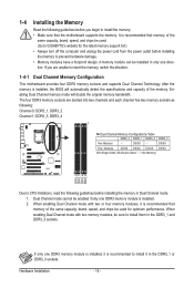
... damage. • Memory modules have a foolproof design. When enabling Dual Channel mode with two memory modules, be used . (Go to GIGABYTE's website for optimum performance. Enabling Dual Channel memory mode will automatically detect the specifications and capacity of the same capacity, brand, speed, and... chips be enabled if only one DDR3 memory module is recommended that the motherboard supports the memory. When enabling Dual Channel mode with two or four memory modules, it is installed, the BIOS will double the...
... damage. • Memory modules have a foolproof design. When enabling Dual Channel mode with two memory modules, be used . (Go to GIGABYTE's website for optimum performance. Enabling Dual Channel memory mode will automatically detect the specifications and capacity of the same capacity, brand, speed, and... chips be enabled if only one DDR3 memory module is recommended that the motherboard supports the memory. When enabling Dual Channel mode with two or four memory modules, it is installed, the BIOS will double the...
Manual
Page 17
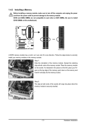
... and unplug the power cord from the power outlet to prevent damage to install DDR3 DIMMs on the socket. Place the memory module on this motherboard. Step 2: The clips at both ends of the memory socket. Follow the steps below to correctly install your fingers on the top edge of the...
... and unplug the power cord from the power outlet to prevent damage to install DDR3 DIMMs on the socket. Place the memory module on this motherboard. Step 2: The clips at both ends of the memory socket. Follow the steps below to correctly install your fingers on the top edge of the...
Manual
Page 18
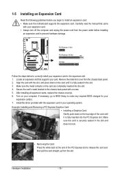
... - Align the card with the expansion card in the slot. 3. If necessary, go to BIOS Setup to install an expansion card: • Make sure the motherboard supports the expansion card. Carefully read the manual that supports your operating system. Remove the metal slot cover from the power outlet before you begin...
... - Align the card with the expansion card in the slot. 3. If necessary, go to BIOS Setup to install an expansion card: • Make sure the motherboard supports the expansion card. Carefully read the manual that supports your operating system. Remove the metal slot cover from the power outlet before you begin...
Manual
Page 19
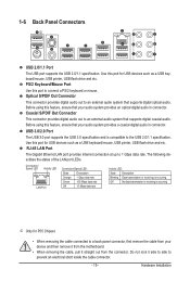
Coaxial S/PDIF Out Connector This connector provides digital audio out to the USB 2.0/1.1 specification. Before using this port for P55 Chipset. • When removing the cable connected to connect a PS/2 keyboard or mouse. USB 3.0/2.0 Port The USB 3.0 port supports the USB 3.0 ... panel connector, first remove the cable from your audio system provides an optical digital audio in connector. Do not rock it straight out from the motherboard. • When removing the cable, pull it side to side to 1 Gbps data rate. 1-6 Back Panel Connectors j USB 2.0/1.1 Port The ...
Coaxial S/PDIF Out Connector This connector provides digital audio out to the USB 2.0/1.1 specification. Before using this port for P55 Chipset. • When removing the cable connected to connect a PS/2 keyboard or mouse. USB 3.0/2.0 Port The USB 3.0 port supports the USB 3.0 ... panel connector, first remove the cable from your audio system provides an optical digital audio in connector. Do not rock it straight out from the motherboard. • When removing the cable, pull it side to side to 1 Gbps data rate. 1-6 Back Panel Connectors j USB 2.0/1.1 Port The ...
Manual
Page 21
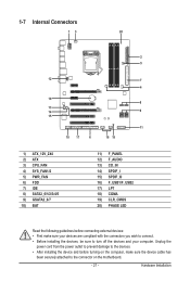
...) CD_IN 14) SPDIF_I 15) SPDIF_O 16) F_USB1/F_USB2 17) LPT 18) COMA 19) CLR_CMOS 20) PHASE LED Read the following guidelines before turning on the motherboard. - 21 - Unplug the power cord from the power outlet to prevent damage to the devices. • After installing the device and before connecting external devices...
...) CD_IN 14) SPDIF_I 15) SPDIF_O 16) F_USB1/F_USB2 17) LPT 18) COMA 19) CLR_CMOS 20) PHASE LED Read the following guidelines before turning on the motherboard. - 21 - Unplug the power cord from the power outlet to prevent damage to the devices. • After installing the device and before connecting external devices...
Manual
Page 22
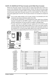
... a power supply providing a 2x4 12V and a 2x12 power connector, remove the protective covers from the 12V power connector and the main power connector on the motherboard. Before connecting the power connector, first make sure the power supply is used that can withstand high power consumption be used (500W or greater). The...
... a power supply providing a 2x4 12V and a 2x12 power connector, remove the protective covers from the 12V power connector and the main power connector on the motherboard. Before connecting the power connector, first make sure the power supply is used that can withstand high power consumption be used (500W or greater). The...
Manual
Page 23
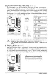
... MB, and 2.88 MB. For purchasing the optional floppy disk drive cable, please contact the local dealer. 33 1 34 2 - 23 - The motherboard supports CPU fan speed control, which requires the use of different color. The types of the connector and the floppy disk drive cable. Hardware Installation...For optimum heat dissipation, it in damage to prevent your CPU and system from overheating. 3/4/5) CPU_FAN/SYS_FAN1/SYS_FAN2/PWR_FAN (Fan Headers) The motherboard has a 4-pin CPU fan header (CPU_FAN), a 4-pin (SYS_FAN2) and two 3-pin (SYS_ FAN1) system fan headers, and a 3-pin power ...
... MB, and 2.88 MB. For purchasing the optional floppy disk drive cable, please contact the local dealer. 33 1 34 2 - 23 - The motherboard supports CPU fan speed control, which requires the use of different color. The types of the connector and the floppy disk drive cable. Hardware Installation...For optimum heat dissipation, it in damage to prevent your CPU and system from overheating. 3/4/5) CPU_FAN/SYS_FAN1/SYS_FAN2/PWR_FAN (Fan Headers) The motherboard has a 4-pin CPU fan header (CPU_FAN), a 4-pin (SYS_FAN2) and two 3-pin (SYS_ FAN1) system fan headers, and a 3-pin power ...


